Table of Contents
Advertisement
Quick Links
Advertisement
Table of Contents

Related Manuals for GeoVision GV-Control Center System V2


Summary of Contents for GeoVision GV-Control Center System V2
- Page 1 GV-Control Center System V2 User’s Manual CCS-UM-A...
- Page 2 GeoVision. Every effort has been made to ensure that the information in this manual is accurate. GeoVision, Inc. makes no expressed or implied warranty of any kind and assumes no responsibility for errors or omissions. No liability is assumed for incidental or consequential damages arising from the use of the information or products contained herein.
- Page 3 Identifies the components of the GV-Control Center System V2. • Chapter 3, Getting Started Provides step-by-step instructions on setting up the GV-Control Center System V2. • Chapter 4, Troubleshooting Suggests courses of action if the GV-Control Center System V2 doesn’t seem to be working properly.
-
Page 4: Table Of Contents
3.6 Configuring the IP Address ................ 18 3.7 Multi Monitors Application ................20 3.7.1 Monitor Arrangement ................20 3.7.2 Matrix View ....................21 3.7.3 Video Wall....................22 3.8 System Restoration..................22 3.9 Updating GV-Control Center System V2 ............ 23 Chapter 4 Troubleshooting ................. 24... -
Page 5: Safety Instructions
Safety Instructions Observe these safety instructions to help ensure against injury to yourself and damage to the product. Read ⚫ all safety and installation instructions before you operate the product. Do not operate ⚫ the product in high humidity areas or expose it to water or moisture. Do not put ⚫... -
Page 6: Chapter 1 Introduction
Chapter 1 Introduction 1.1 Packing List The GV-Control Center System V2 package includes the following items. If any of the items are missing or damaged, contact your dealer to arrange a replacement. Important: Please keep the original carton and all packing materials for future shipping need. -
Page 7: Chapter 2 Overview
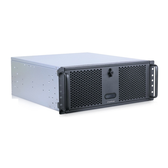
Chapter 2 Overview 2.1 Front View Figure 2-1 No. Name Name USB 3.0 (Type-A) x 2 Power LED Power Button HDD LED Reset Button LAN LED (No. 2 not functional) -
Page 8: Rear View
Overview 2.2 Rear View Figure 2-2 Name Name Power Connector DisplayPort 1.4 x 4 (up to 4K / 60Hz) Power Switch HDMI 2.0 x 2 (up to 4K / 60Hz) ECO Switch 2.5 GbE LAN x 2 PS/2 keyboard / mouse port USB 3.2 (Type-A) x 2 USB 2.0 (Type-A) x 4 USB 3.2 (Type-C) -
Page 9: Chapter 3 Getting Started
Chapter 3 Getting Started 3.1 Basic Installation This section describes all the equipment required to program and operate the GV-Control Center System V2. Figure 3-1 1. Connect the mouse and keyboard to any of the USB ports or the PS/2 port. 2. -
Page 10: Installing The Hard Drive
Getting Started Installing the Hard Drive 1. Unscrew the two screws on each side of the system (a total of 4 screws). Figure 3-2 2. Pull out the motherboard tray. Figure 3-3 3. Unscrew the set screws on the top of the hard drive bracket. Figure 3-4... - Page 11 4. Turn the knob anticlockwise on the front panel and open the front panel. Figure 3-5 5. Turn the knob next to the fan and open the fan bracket. Figure 3-6...
- Page 12 Getting Started 6. Push the hard drive bracket to the right to loosen the bracket from the pads, and lift up the bracket. Figure 3-7 7. Place the hard drive onto the hard drive bracket. Align and tighten the two screws on each side to secure the hard drive (a total of four screws).
- Page 13 10. Align the hard drive bracket with the pads at the bottom of the system case. Carefully check if the pads all fit in the holes at the bottom of the bracket since the hard drives installed on the bracket may block the views. Figure 3-9 11.
- Page 14 Getting Started 12. Push the motherboard tray back into the system case. Align and tighten the screws on both sides of the system. Tips: In Step 7, begin by installing a hard drive onto the bottom of the hard drive bracket. Leave one side of the screws partially tightened to make it easier to align the second hard drive on top.
-
Page 15: Turning On The Power
3.3 Turning on the Power To turn on the power, follow these steps: 1. Turn on the monitor. Figure 3-11 2. Make sure the Power Switch is switched ON on the rear panel, and turn on the main power switch on the front panel. Rear panel Figure 3-12 Front panel... - Page 16 Getting Started GV-Control Center System V2 will run a series of self-tests, and later series of messages may be displayed as the various hardware and software subsystems are activated. Note: The series of self-tests will take around 20 seconds to 2 minutes, depending on the...
-
Page 17: Windows Setup Installation
3.4 Windows Setup Installation The Windows setup is preparing your computer for first use. 1. After the Windows starts, this setup screen appears. Select your language and click Next to continue. Figure 3-14 2. Select your regional settings and time zone and click Next to continue. Figure 3-15 3. - Page 18 Getting Started 4. Select between “Customize” and “Use Express settings” for your Windows 10 installation. 5. Type your account name. It is recommended that you create a password for your account and click Next. Figure 3-16 6. When the above setup process is complete, Windows will finalize your settings automatically in the background and restart.
-
Page 19: Formatting The Hard Drive
3.5 Formatting the Hard Drive Be sure to install each of your hard drives separately for formatting. Do not install and format more than one hard drive at a time. To format a hard disk, follow the steps below: 1. Right-click the Computer icon on your desktop, select Manage, and select Disk Management when the Computer Management window appears. - Page 20 Getting Started The New Simple Volume Wizard appears. Click Next to continue. Figure 3-19 6. The default partition size is the same as the maximum disk space. Make changes if necessary. Click Next to continue. Figure 3-20...
- Page 21 7. Assign a drive path that is not in use by other devices, and click Next to continue. Figure 3-21 Note: The default drive path starts from D:\. 8. Type a name in the Volume label box, ex. HDD1, and click Next to continue. Figure 3-22...
- Page 22 Getting Started 9. When the formatting is complete, click Finish to close the wizard. Figure 3-23 10. When the drive is successfully initialized, partitioned, and formatted, its status description should display “Healthy.” Figure 3-24...
-
Page 23: Configuring The Ip Address
3.6 Configuring the IP Address GV-Control Center System V2 supports remote monitoring, control and configuration over a network connection. The system supports up to 2 Ethernet ports. Figure 3-25 (Note: The figure is for reference only. The rear panel may vary due to product enhancement.) - Page 24 Getting Started 4. Select Internet Protocol Version 4 (TCP/IPv4) and then click Properties. Figure 3-28 5. Select Use the following IP address and type the new IP information in the fields or select Obtain an IP address automatically to enable dynamic IP address. Figure 3-29 6.
-
Page 25: Multi Monitors Application
3.7 Multi Monitors Application 3.7.1 Monitor Arrangement You can display multiple views on up to 8 ~ 9 monitors simultaneously based on the selected preinstalled GV-Control Center version. 1. Right-click on the screen and select Display settings. Figure 3-30 2. In the Display window, select a monitor to be the main display, and select Make this my main display. -
Page 26: Matrix View
Getting Started 3.7.2 Matrix View & Multiple Live View With the preinstalled GV-Control Center of different versions, its Matrix View / Multiple Live View function allows users to configure multiple displays on different monitors. [Matrix View] With the preinstalled with GV-Control Center V3, its Matrix View function allows the center operator to monitor up to 96 cameras from different hosts on the same screen. -
Page 27: Video Wall
3.7.3 Video Wall A Video Wall is an establishment of multiple monitors on a server, displaying composite IP sources from various IP devices. Using the Control Center System, you can remotely manage up to 200 Video Walls, each with a different layout. On each Video Wall, you can: ... -
Page 28: Updating Gv-Control Center System V2
Getting Started 3.9 Updating GV-Control Center System V2 If you like to update your GV-Control Center System V2, contact your dealer for more information. Before contacting your dealer, you may check software update news at our website: http://www.geovision.com.tw... -
Page 29: Chapter 4 Troubleshooting
1. Restart your GV-Control Center System V2 by pressing the Reset button on the front panel. 2. If your GV-Control Center System V2 is still unresponsive, press the Power button on the front panel for 10 seconds or switch off the Power Switch on the rear panel to shut down the system. - Page 30 Rear Panel Figure 4-2 GV-Control Center System V2 is unable to start. If your GV-Control Center System V2 is unable to start after you push the Power button, try these steps: 1. Remove the power cord from the power connector.
- Page 31 GV-Control Center System V2’s hard disk corrupts. If you are experiencing file system corruption problems, such as lost clusters, cross-linked files or invalid files or directories, try these steps: 1. Use the HD Tune utility to scan the hard disk for errors. Follow these steps: A.
- Page 32 Troubleshooting 2. If the HD Tune utility does not find any defects, use the Windows built-in utility to attempt to fix the errors. Follow these steps: A. Right-click the Computer icon on your desktop, select Manage, and select Disk Management when the Computer Management window appears. B.
- Page 33 4. If the problem persists, replace a hard disk drive. GV-Control Center System V2 suffers virus attack. GV-Control Center System V2 is designed and optimized for Windows 10 platform. It may be vulnerable to newly created worms and exploits that attack any of the underlying operating system’s previously undocumented flaws.
Need help?
Do you have a question about the GV-Control Center System V2 and is the answer not in the manual?
Questions and answers