GeoVision GV-AS100 Hardware Installation Manual
Gv-as series
Hide thumbs
Also See for GV-AS100:
- User manual (235 pages) ,
- Quick start manual (17 pages) ,
- Installation manual (172 pages)

Related Manuals for GeoVision GV-AS100


Summary of Contents for GeoVision GV-AS100
- Page 1 GV-AS Controller Hardware Installation Guide Before attempting to connect or operate this product, please read these instructions carefully and save this manual for future use.
- Page 2 9F, No. 246, Sec. 1, Neihu Rd., Neihu District, Taipei, Taiwan Tel: +886-2-8797-8377 Fax: +886-2-8797-8335 http://www.geovision.com.tw Trademarks used in this manual: GeoVision, the GeoVision logo and GV series products are trademarks of GeoVision, Inc. Windows and Windows XP are registered trademarks of Microsoft Corporation. October 2009...
-
Page 3: Table Of Contents
Contents Welcome........................v Optional Devices ..................... vi Work Modes ......................vii Installation Considerations..................vii 1. GV-AS100 Controller .................... 1 1.1 Introduction .........................2 1.1.1 Main Features....................3 1.1.2 Packing List .....................3 1.1.3 GV-AS100 Board Layout .................3 1.2 Installation........................4 1.2.1 Connecting a Wiegand Reader ...............5 1.2.2 Connecting Input Devices................5... - Page 4 1.4.4.A Connecting GV-AS100 ..............21 1.4.4.B Connecting a Wiegand Reader............22 1.4.4.C Connecting a GeoFinger Reader............22 1.4.4.D Connecting Input Devices...............23 1.4.4.E Connecting Output Devices ............24 1.4.4.F Other Settings .................26 1.4.5 Web-Based Configurations ..................27 1.4.5.A Basic Setting...................27 1.4.5.B Advanced Settings................28 1.6 Specifications......................47 1.6.1 GV-AS100 .....................47 1.6.2 Optional GV-ASBox ..................48...
- Page 5 2.3.3 Status LEDs....................63 2.4 GV-ASKeypad ......................64 2.4.1 Installation .....................64 2.4.2 Operation.......................65 2.4.2.A Setting Parameters .................65 2.4.2.B Displaying System Information ............66 2.5 GV-AS200E ......................67 2.5.1 Installing GV-AS200E on a Network..............67 2.5.1.A Fixed IP Connection ...............67 2.5.1.B DHCP Connection ................69 2.5.2 System Settings.....................76 2.5.2.A System Setup .................76 2.5.2.B Updating Firmware .................77 2.5.2.C Changing Login ID and Password ..........78...
- Page 6 3.4.1 Installing on the Network ................96 3.4.2 Basic Setting....................96 3.4.3 Advanced Settings..................97 3.4.3.A Function Setting................98 3.4.3.B Parameter Setting.................100 3.4.3.C Time Setting .................104 3.4.3.D Input Function................105 3.4.3.E Output Function ................107 3.4.3.F Output Function ................111 3.4.4 Extended Device ..................112 3.4.4.A Extended Reader................112 3.4.4.B Extended I/O.................113 3.5 Optional GV-ASKeypad ..................114 3.5.1 Installation ....................114...
-
Page 7: Welcome
Welcome This user manual includes three types of GV-AS Controllers: • GV-AS100: One door controller and standalone system. See page 1. • GV-AS200: Two to four-door controller. See page 49. • GV-AS400: Four-door controller. See page 81. -
Page 8: Optional Devices
GeoFinger Reader enrolled through GV-ASManager software. In Fingerprint + Card mode, the fingerprint templates are stored on the user card. Only works with GV-AS100. The device can add network function, GV-ASBox 1 Wiegand interface, 8 additional inputs and outputs to GV-AS100. -
Page 9: Work Modes
RS-485 interface: 600 meters (1968.50 feet) • Recommended cable: standard 485 cable (a twisted pair of 24 AWG wires) 2. GV-ASManager software is used to manage GV-AS100/GV-AS200/GV-AS400 Controllers. There is a limit for the number of controllers connected to GV-ASManager based on communication modes. -
Page 11: Gv-As100 Controller
1. GV-AS100 Controller... -
Page 12: Introduction
Working as a standalone solution, GV-AS100 is a card reader and also a single door controller. It is possible to add one more card reader to GV-AS100 for entry and exit applications. GV-AS100 has the capability to store up to one thousand cards. When GV- AS100 is being used as a standalone unit the programming is either done on the keypad or from the software GV-ASManager through the RS-485 connection. -
Page 13: Main Features
Anti-Passback (APB) support • Built-in 3 digital inputs and 2 relay outputs • 1 Weigand output (26 ~ 64 bits) for extra reader programming 1.1.2 Packing List • GV-AS100 • Power Adaptor 12V DC 1.1.3 GV-AS100 Board Layout Figure 1-2... -
Page 14: Installation
1.2 Installation Please open GV-AS100 cabinet and wire the necessary connections to the terminal block as illustrated below. Door 19 NO Door 18 NC Door 17 COM Alarm 16 NO Alarm 15 COM 14 IN 13 IN3 Fire 12 IN2... -
Page 15: Connecting A Wiegand Reader
GV-AS100 provides one Wiegand input for connection of the Wiegand reader ranging from 26 to 64 bits. Through the GV-AS100 keypad, you can set the Wiegand reader as the entry or exit reader. To define the reader, see the AS100 Function option in 1.3.4 Setting Parameters. -
Page 16: Connecting Output Devices
The example below illustrates the connection of a locking device to GV-AS100. Connect the (+) point on the locking device to the Door COM on GV-AS100, connect the two (-) points of the locking device and the external power supply together, and connect the (+) point on the external power supply to the Door NO or Door NC on GV-AS100 based on the state of the locking device. -
Page 17: Connecting The Pc
The computer running GV-ASManager software can be used to monitor the access information and alarm messages from GV-AS100. The communication link between the computer and GV-AS100 can be either RS-485 or network. For network connection, an optional GV-ASBox is required. -
Page 18: B Network Connection
Also see 1.4.3.A Connecting GV-AS100. 1.2.4.C Switches Switch 1: When Switch 1 is ON, GV-AS100 can connect to GV-ASManager or GV-ASBox. When Switch 1 is OFF, the connection is unavailable. By default Switch 1 is set to ON. Switch 2: When the RS-485 connection between GV-AS100 and computer is longer than 600 meters (1968.50 feet), the RS-485 signal may become weak. -
Page 19: Connecting The Power
When the power in the battery becomes low, the message “Low Battery” will appear on GV-AS100 LCD. In this case, please replace the battery. The database on GV- AS100 will remain about 10 hours after the battery stops working. -
Page 20: Programming Mode
1.3 Programming Mode After powering on GV-AS100, you must create a Master Card first. It is required to present the Master Card and enter its PIN code every time before programming GV-AS100. Note: The card complying with ISO 14443A standard for smart card technology can be formatted as a Master Card. - Page 21 GV-AS100 Controller Before programming GV-AS100, you also need to know the following keys. Function Used to cancel the selection, or go back to the previous page. * Used to save the data that was modified or programmed in the system and quit.
-
Page 22: Quick Reference Of Programming Table
1.3.1 Quick Reference of Programming Table Card Manger Add New Card 1) N, 2) A, 3) B, 4) S Del Card Data Reset Card’s APB Display System Door’s Auth Mode Door’s Event ASBox Comm. State Memory’s State ID & IP Address Display Version Set Parameter Set Local Time... -
Page 23: Accessing The Card Manager
The Card Manager option is used to add cards, delete cards and reset the card’s APB function. Note: 1. GV-ASManager cannot manage the cards enrolled on GV-AS100, since the card data will not be transmitted to GV-ASManager. 2. The cards added through GV-ASManager cannot be deleted on GV-AS100. -
Page 24: C Resetting The Apb Function
1.3.3 Accessing the Security Mode The security mode is used to arm GV-AS100. In the arm mode, no cards can be granted access and no one can program the unit. Only the security card that is associated with a PIN code can be used to disarm the unit. -
Page 25: Setting Parameters
You can define the parameters of some features on GV-AS100. IMPORTANT: Once connecting to GV-AS100, GV-ASManager will load its parameters to GV-AS100. That means some of parameters you set up here may be overwritten by GV- ASManager later. 1. Press the code *738 (*SET). - Page 26 Note: The Parking Entry Type and Parking Exit Type only work when the sensor input of Car Detection is activated. When the card is present but the sensor inputs are not activated, the message “No Car In Zone” will appear in the GV-AS100’s LCD.
-
Page 27: Displaying System Information
Capacity: Displays the total number of events that can be recorded on GV-AS100. The maximum number is 65536. GV-AS100 will rewrite the oldest events when the limit is reached. When GV-AS100 is connected to GV-ASManager, the event data will be uploaded to the server and the buffer of GV-AS100 will be cleared. -
Page 28: Restoring Factory Defaults
1.3.6 Restoring Factory Defaults The restore function is used to clear all configured options and cards from GV-AS100 memory and bring back the unit to factory defaults. IMPORTANT: Restoring default settings will delete all cards enrolled on GV-AS100. 1. Press the code *737 (*RES). -
Page 29: Optional Gv-Asbox
GV-AS100 Controller 1.4 Optional GV-ASBox The optional GV-ASBox is the I/O and network expansion module for GV-AS100. With the GV-ASBox, additional network connectivity, 8 inputs, 8 inputs and 1 Wiegand reader can be added to GV-AS100. 1.4.1 Main Features •... -
Page 30: Gv-Asbox Board Layout
1.4.3 GV-ASBox Board Layout Figure 1-9... -
Page 31: Installation
GV-AS100. Figure 1-10 Function Function Function 12V Power Supply GV-AS100 GV-AS100 Connection Connection to GV-AS100 GND for Power Supply GV-AS100 GV-AS100 Connection Connection to GV-AS100 For connection to GV-AS100, two switches (RS-485_A Term and RS-485_B Term) must be turned ON. -
Page 32: B Connecting A Wiegand Reader
GV-ASBox provides one Wiegand input for connection of the Wiegand-compatible reader ranging from 26 to 64 bits. The connected Wiegand reader can either work with GV-AS100 to carry out entry and exit applications on a single door, or be installed on another door for the two-door application. -
Page 33: D Connecting Input Devices
GV-AS100 Controller To define each GeoFinger reader, you need to use the GV-AS100 Web interface. See 1.4.5.B.g GeoFinger Setting. Note: The RS-485 connector on GV-ASBox is only designed for the connection of GeoFinger reader. 1.4.4.D Connecting Input Devices GV-ASBox provides 8 inputs (DI1 to DI8). All inputs are dry contact and can be configured as normally open (NO) or normally closed (NC) through the Web interface. -
Page 34: E Connecting Output Devices
1.4.4.E Connecting Output Devices GV-ASBox provides 8 outputs and 2 auxiliary power outputs of 12V DC. The outputs are divided into two groups, outputs 1 ~ 4 and outputs 5 ~ 8. Before connecting, make sure if your output device meets any of the two different absolute maximum ratings listed below. Additionally, you can wire the light switch to the outputs 5 ~ 8 for lighting control. - Page 35 GV-AS100 Controller To connect an output device: GV-ASBox provides two auxiliary power outputs of 12V DC at a maximum current of 1A. If you output device requires higher current, you must have the power supplied from an external power supply. Connect the (+) point on the output device to COM on GV-ASBox,...
-
Page 36: F Other Settings
1.4.4.F Other Settings The figure below shows the location of the Web Setting Switch, Reset Button and Default Button. Figure 1-15 1.4.3.F.a Web Setting Switch When the Web Setting switch is set to ON, you can modify Advanced Settings of GV- AS100 through the Web interface. -
Page 37: Web-Based Configurations
GV-AS100 Controller 1.4.5 Web-Based Configurations Through GV-ASBox, GV-AS100 can communicate with GV-ASManager over the network. Also through GV-ASBox, you can access the GV-AS100’s Web interface. Designed for use on the network, GV-ASBox must be assigned an IP address to make it accessible. -
Page 38: B Advanced Settings
1.4.5.B Advanced Settings You can execute and edit door/Wiegand operations and settings, turn on Alarms, view status, display card information stored in GV-AS100, set the device time and edit the input/output functions. The changes in some of the Advanced Setting page will effect the options available on other pages. - Page 39 Figure 1-17 [ID] Enter the ID number for GV-AS100. This ID is used by GV-ASManager to differentiate among multiple units of GV-AS100. ID number can only be between 1 and 255. [ASBox Wiegand] Select the function for Wiegand Input on GV-ASBox from the drop-down list.
- Page 40 Select the function type and authentication mode for the use of Door/Gate A. Function: Select the function for GV-AS100 on Door/Gate A. Door Entry Control: Sets GV-AS100 as entry reader on the Door A. The Weigand reader connected on GV-AS100 will be set as exit reader.
- Page 41 For details on setup, see Chapter 6 Anti-Passback on GV-ASManger User’s Manual. Enable/Disable: Enables or disables the Anti-Passback function. Info IP: Enter the IP address of the next corresponding GV-AS100. [Delete MasterCard] Delete: Click the Delete button to delete the current MasterCard information.
- Page 42 Door/Gate B in the Function Setting page (Figure 1-17). Figure 1-18 IMPORTANT: Once connecting to GV-AS100, GV-ASManager will load its parameters to GV-AS100. That means some of the Parameter Settings you have configured here may be rewritten by GV-ASManager later.
- Page 43 GV-AS100 Controller [Events] Set the parameters for the events. Figure 1-19 • When Door Entry/Exit Control or Parking Entry/Exit Control is selected in the Function Setting page (Figure 1-17), these options become available: Option Description Anti-Passback Enables or disables the Anti-Passback function. The option is only available for Door/Gate A.
- Page 44 [Alarm] Select Yes or No to enable or disable the alarm function. If you have defined the alarm conditions in [Output Function] of the In/Out Function page (Figure 1-25), remember to activate the corresponding alarms here; otherwise, even though the alarm conditions are met, the expected alarm will not be triggered.
- Page 45 GV-AS100 Controller [Common Password] When Fixed Card/Common Mode is selected as Authentication Mode in the Function Setting page (Figure 1-17), you can either gain access through the use of a card or use this Common Password to enter. Figure 1-21 [AS100 Input Name] Rename the input names for the four AS100 inputs.
- Page 46 1.4.5.B.c Status Monitor In the left menu, click Status Monitor. This page appears. Figure1-22 [Status Monitor] Status Monitor displays the current status of each input, output and alarm. Control Mode will change depending on the chosen Door/Gate’s Authentication Mode in the Function Setting page (Figure 1-17).
- Page 47 Shows the number of cards currently stored in GV-AS100. [Card List] Displays the list of cards stored in GV-AS100. If there are many pages, you can choose to jump to any page by entering the page number in the Page field.
- Page 48 Time Zone: Displays the current time zone of GV-AS100. [Local Time] Disable: Disable the manual configuration of time and date. Setup: Enable the manual configuration of Time Zone, Date and Time for GV-AS100. [Daylight Savings Time (DST)] Disable: Disable the manual configuration of DST.
- Page 49 GV-AS100 Controller 1.4.5.B.f In/Out Function In the left menu, click In/Out Function. This AS100 IO Configuration page appears. Figure 1-25 [Input Function] Here you can define each sensor input that is connected GV-ASBox and select the most fitting Input Type (No. 3, Figure 1-26) and Input Function (No. 4, Figure 1-26) to describe the sensor input.
- Page 50 3. Input Type: Configure the input type. Input Type defines the type of sensor that is connected to the input of GV-ASBox. Options available for the input type change based on your settings of Door/Gate A and Door/Gate B in the Function Setting page (Figure 1-17).
- Page 51 GV-AS100 Controller • When Elevator Control is selected in the Function Setting page (Figure 1-16), these Input Type and Input Function become available: Input Type Input Function Description Normal Input Enable Latch See the same Input Type above. Disable Latch...
- Page 52 Output Function Settings: When Output Type (No. 1, Figure 1-27) is set to be Door #, Gate # or Relay #, the options similar to the figure below become available. Figure 1-28 Below is the explanation based on the numbers marked on the above figure. 1.
- Page 53 GV-AS100 Controller • When Parking Entry/Exit Control is selected in the Function Setting page (Figure 1- 17), these Output Type and Output Function become available: Output Type Output Function Description Gate # Electric Lock See the same function above. Alarm Event...
- Page 54 Output Condition Settings: When Output Type (No. 1, Figure 1-27) is set to be Normal, Toggle, Pulse, Normal Lighting, Toggle Lighting or Pulse Lighting, the options similar to the figure below become available. 2 x Door/Gate/Relay Conditions 2 x Input Conditions Available in Pulse/Lighting Figure 1-29...
- Page 55 GV-AS100 Controller In the Output Condition Settings, these Output Type and Output Condition options become available: Output Type Output Condition Door A or B Gate A or B Relay A or B Input (x2) Normal Access Granted Access Granted Access Granted...
- Page 56 In the left menu, click Extended GeoFinger. This Finger Configuration page appears. Figure 1-30 Define each GeoFinger reader connected to GV-AS100. Select which door that the GeoFinger is installed and type XID number (serial number) found on GeoFinger. Click Submit to detect GeoFinger. If any GeoFinger is detected, a green mark will appear in the...
-
Page 57: Specifications
GV-AS100 Controller 1.6 Specifications 1.6.1 GV-AS100 8-bit RISC microprocessor Number of User Cards 1,000 / 40,000 cards (standalone / networked mode) Event Buffer 65,536 events and log data Power 100 ~ 240V AC, 50 ~ 60Hz 1 Wiegand interface, 26 ~ 64 bit format... -
Page 58: Optional Gv-Asbox
1.6.2 Optional GV-ASBox 8-bit RISC microprocessor Event Buffer 65,536 events and log data Power 100 ~ 240V AC, 50 ~ 60Hz 1 Wiegand interface, 26 ~ 64 bit format Wiegand Interface 12V DC Power Supply, 200mA Communication Protocol RS-485 Input 3 inputs, dry contact, NO / NC Digital I/O Output... -
Page 59: Gv-As200 Controller
2. GV-AS200 Controller... -
Page 60: Introduction
2.1 Introduction 2.1.1 Main Features • 2 doors expandable to 4 doors with optional Expansion I/O Module • Support 4 Wiegand card readers of 26~40 bits • Support up to 8 card readers via RS-485 connection • Each door supports door opener, door status sensor, fire detector and tamper detector •... -
Page 61: Gv-As200 Board Layout
GV-AS200 Controller 2.1.4 GV-AS200 Board Layout Fuse2 Door B Door A Wiegand A Wiegand D Wiegand C Wiegand B (Special Terminal) Reset Door A Door B Door C Door D Green: Green: ON:Door Open ON:Door Open Reset EN AS200 Flash:Hold Open Alarm Flash:Hold Open Alarm Yellow: Yellow:... -
Page 62: Installation
2.2 Installation Please open the GV-AS200 cabinet and wire the necessary connections to the GV-AS200 module. 2.2.1 Connecting the PC RS-485 GV-HUB / GV-COM / GV-NET/IO Card V3.1 Figure 2-2 The connected computer running GV-ASManager software can be used to monitor the access information and alarm messages from GV-AS200. -
Page 63: Connecting Inputs
GV-AS200 Controller 2.2.2 Connecting Inputs GV-AS200 supports four types of digital inputs for each door: 1. Button inputs, e.g. door opener 2. Sensor inputs, e.g. door status sensor 3. Fire inputs, e.g. fire detector 4. Tamper inputs, e.g. tamper detection sensor The inputs located at the bottom of the GV-AS200 module are illustrated as shown below. -
Page 64: B Senor Inputs
2.2.2.B Senor Inputs The Sensor inputs can connect to a door’s micro switch for door status monitoring. Triggering the Sensor inputs can generate the two alarm states: 1. Force alarm: when the door is forcibly opened by unauthorized persons. 2. Door held open alarm: when the door is open for a period of time exceeding the programmed open time. -
Page 65: F Input No And Nc Switches
GV-AS200 Controller 2.2.2.F Input NO and NC Switches Using the switches to set the four digital inputs for NO (normally open) or NC (normally closed) mode. Door (A,B,C,D) Input type ON:NC type OFF:NO type 1 2 3 4 5 6 7 8 Figure 2-6 2.2.3 Connecting Outputs GV-AS200 supports three types of relay outputs for each door:... -
Page 66: A Door Outputs
This figure illustrates the wiring for the output relay when the door relay is set to be normally closed. Door Relay of Normally Closed FIRE FIRE FIRE Figure 2-8 This figure illustrates the wiring for the output relay when the door relay is set to be normally open. -
Page 67: B Alarm Outputs
GV-AS200 Controller 2.2.3.B Alarm Outputs The Alarm outputs can connect to an alarm annunciator such as siren or bell. 2.2.3.C Urgent Outputs The Urgent outputs can connect to a button or device that releases a door without reading a card. Note: 1. -
Page 68: Connecting Card Readers
2.2.4 Connecting Card Readers GV-AS200 supports two types of card readers: Wiegand and RS-485 interfaces. The Wiegand interface is compatible with any Wiegand card readers of 26 to 40 bits, while the RS-485 interface is only compatible with GV-Readers. The card readers of the two interface types can be used together to work with GV-AS200. -
Page 69: B Rs-485 Readers
GV-AS200 Controller 2.2.4.B RS-485 Readers For long-distance connection and non-Weigand card readers, you can choose the RS-485 connection. Up to 8 units of GV-Readers can be connected with a single RS-485 cable to the RS-485 interface on GV-AS200. By default GV-AS200 is set to the Wiegand signal. For the RS-485 communication, you need to change the parameter GV-Reader ID to Extended Wiegand by using GV- ASKeypad. - Page 70 Corresponding Tables between Doors and Card Readers The following tables show how and where each card reader should be placed based on different work modes. Wiegand Card Readers The default 2-door applications: Door A and Door B Door A Door B Work Mode One-way control Wiegand A...
-
Page 71: Connecting The Power
GV-AS200 Controller 2.2.5 Connecting the Power After all wiring is complete, power on GV-AS200. 1. Plug one end of the supplied power cable into the 6-pin connector on the power converter, and the other end into the three power connectors on the GV-AS200 module: •... -
Page 72: Operation
2.3 Operation 2.3.1 Resetting GV-AS200 1. To reset GV-AS200, press the Reset button located at the upper right of the GV-AS200 circuit board for 3 seconds. 2. To reset the Ethernet module, press the Reset EN button located in the middle left of the GV-AS200 circuit board for 3 seconds. -
Page 73: Status Leds
GV-AS200 Controller 2.3.3 Status LEDs Door A Door B Door C Door D Light On Flashing Green LED Door open Alarm: Door held open Yellow LED Door opener active Password Fire detector active Alarm: Tamper sensor active... -
Page 74: Gv-Askeypad
2.4 GV-ASKeypad The GV-ASKeypad is an optional device for an administrator to control and manage GV- AS200. An administrator can carry the GV-ASKeypad around to access GV-AS200s installed at different locations. 2.4.1 Installation 1. Open the GV-AS200 cabinet. 2. Flip both clips of the 26-pin connector on the GV-AS200 module. 3. -
Page 75: Operation
GV-AS200 Controller 2.4.2 Operation GV-ASKeypad allows you to configure basic settings and view system information of GV- AS200. 2.4.2.A Setting Parameters To set parameters of GV-AS200: Press any buttons on the keypad, select Set Parameter, and press the button. Press the default password 1234. To set parameters: •... -
Page 76: B Displaying System Information
2.4.2.B Displaying System Information To display system information: 1. Press any buttons on the keypad. The message Set Parameter appears. 2. Press the Down arrow button to display the message Display System, and press the button. 3. To change options or view the status of each door, press the Up and Down arrow buttons. Function Option Door’s Control... -
Page 77: Gv-As200E
GV-AS200 Controller 2.5 GV-AS200E GV-AS200E, equipped with the Ethernet Module, can communicate with GV-ASManager over the network. The following sections describe how to install GV-AS200E on the network and how to configure GV-AS200E over the network. 2.5.1 Installing GV-AS200E on a Network GV-AS200E is able to support two network environments: Fixed IP and DHCP. - Page 78 To assign GV-AS200E to a fixed IP: 1. Open an Internet browser, and type the default IP address https://192.168.0.100. This dialog box appears. Figure 2-16 2. Click default value admin for both User name and Password, and click OK. This page appears.
-
Page 79: B Dhcp Connection
DDNS servers to map a dynamic IP address to a static domain name or device name: • For LAN connection, GV LocalDDNS Server is provided. • For Internet connection, two DDNS servers are supported: GeoVision DDNS Server and Dynamic Network Services Inc. (DynDNS). - Page 80 Installing LocalDDNS Server To install the LocalDDNS Server in a computer, insert the Software CD. It will run automatically and a window appears. Select Install GeoVision V2.1 Access Control System, click GeoVision Dynamic DNS Service and follow the on-screen instructions.
- Page 81 GV-AS200 Controller Configuring GV-AS200E on LAN After running the LocalDDNS Server, configure GV-AS200E on LAN: 1. Open an Internet browser, and type the default IP address https://192.168.0.100. The login dialog box (Figure2-16) appears. 2. In the User Name and Password fields, type default value admin and 1234 respectively. Click OK.
- Page 82 6. Click Submit to send the information to the LocalDDNS Server. When the setting is complete, the Status field will indicate: Register Success. Then GV-AS200E can be accessed with the device name. Note: 1. The default value of Device Name is user. If more than one GV-AS Controller is connected to the GV-ASManager, assign each controller a different device name.
- Page 83 Figure 2-21 Registering a DDNS Domain Name To obtain a domain name from the GeoVision DDNS Server: 1. Click the GeoVision DDNS button on the Network Configuration page (Figure 2-19). Or open an Internet browser, and type the Web address http://ns.dipmap.com/register.aspx...
- Page 84 Figure 2-22 2. In the Username field, type a name. Username can be up to 16 characters with the choices of “a ~ z”, “0 ~9”, and “-”. Note that space or “-” cannot be used as the first character. 3.
- Page 85 3. Click Enable, and select Send to DDNS. 4. Type Host Name, User Name and Password that are registered on the DDNS Server. If you select GeoVision DDNS, the system will automatically bring up the Host Name. Figure 2-24 5. Click Submit. When the setting is complete, the Status field will indicate: Register...
-
Page 86: System Settings
2.5.2 System Settings You can execute certain system operations, change login password and view the version information of the firmware. 2.5.2.A System Setup In the left menu, click Other Setting. This page appears. Figure 2-25 3DES Code 1-3: Stands for Triple DES (Data Encryption Standard). Type up to three different keys for data encryption. -
Page 87: B Updating Firmware
GV-AS200 Controller 2.5.2.B Updating Firmware To update the firmware of GV-AS200E: 1. In the left menu, click Firmware Update. This page appears. Figure 2-26 2. Click the Browse… button to open the firmware file (*.bin) 3. Click the Upload button. This update procedure may take 60 seconds to complete. 4. -
Page 88: C Changing Login Id And Password
2.5.2.C Changing Login ID and Password To change the login ID and password: 1. In the left menu, click Security Setting. 2. On the Security Configuration page, modify the login name and password. The password is case sensitive and is limited to 4 characters with the choices of “a ~ z” and “0 ~ 9”. Figure 2-28 2.5.2.D Setting Controller ID and Work Mode The setting page allows you to modify the ID of GV-AS200E and set one work mode for... -
Page 89: Gv-As200 Specifications
GV-AS200 Controller 2.6 GV-AS200 Specifications Model (Default) GV-AS200 8-bit RISC microprocessor Number of User Cards 10,000 cards Event Buffer 65,536 events and log data Power 100 ~ 250V AC, 50 ~ 60Hz 4 Wiegand Interfaces Reader Port 1 RS-485 interface only for GV-Readers (max. 8 GV-Readers) 26 ~ 40 bit format Wiegand Interface 12V DC power supply... -
Page 90: Troubleshooting
2.7 Troubleshooting The card reader does not respond after being installed. If the card reader does not respond, it may be due to the power problem. Try these steps: 1. To verify the problem, remove the paper covered on the GV-AS200 module and check if the power light of the card reader is ON. -
Page 91: Gv-As400 Controller
3. GV-AS400 Controller... -
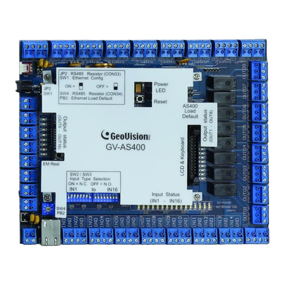
Page 92: Introduction
3.1 Introduction 3.1.1 Main Features • Support 8 Wiegand card readers of 26 to 64 bits • Support 4 GV-Readers and GeoFinger readers through RS-485 connection • Built-in 16 digital inputs and 16 relay outputs • I/O capability expandable to 64 digital inputs and 64 relay outputs with GV-IO USB Box connected •... - Page 93 GV-AS400 Controller 3.1.3 GV-AS400 Board Layout Wiegand A Wiegand B Wiegand C Wiegand D Wiegand E Wiegand F Wiegand G Wiegand H 1 2 3 4 5 6 7 8 1 2 3 4 5 6 7 8 RS-485 Figure 3-1...
-
Page 94: Installation
3.2 Installation When you wire any devices to GV-AS400 circuit board, please note: • Carefully remove the blue terminal block and note the block’s terminal markings on the circuit board. After wring the necessary connections to the terminal block, reinsert it onto the circuit board. -
Page 95: A Wiegand Readers
GV-AS400 Controller 3.2.1.A Wiegand Readers GV-AS400 provides 8 Wiegand inputs (Wiegand A to Wiegand H) for connection of Wiegand readers ranging from 26 to 64 bits. The table below shows the pin assignments of Wiegand inputs on GV-AS400. Please consult the documentation of your Wiegand reader for wiring. Function GND of the Power Supply Wiegand Data 0... -
Page 96: B Rs-485 Readers
3.2.1.B RS-485 Readers For long-distance connection and non-Weigand card readers, you can choose the RS-485 connection. Up to 4 units of GV-Readers and/or GeoFinger 1901/1902 readers can be connected together with a single RS-485 cable to the RS-485 interface on GV-AS400. To connect GV-Reader: Refer to the figure and table below for wiring. -
Page 97: Connecting Input Devices
GV-AS400 Controller To connect GeoFinger readers: If more than one GeoFinger reader is connected to GV-AS400, an extra power supply is required to drive each GeoFinger reader. Use 12V pins on the Weigand connectors to power on each GeoFinger reader. 3.2.2 Connecting Input Devices GV-AS400 provides up to 16 inputs. -
Page 98: Connecting Output Devices
3.2.3 Connecting Output Devices GV-AS400 provides up to 16 outputs. They are divided into two groups, outputs 1 ~ 8 and outputs 9 ~16, located at opposite sides of GV-AS400. The two groups of outputs have different absolute maximum ratings. Outputs 1 ~ 8 support the external power supply, while outputs 1 ~ 8 only accept the internal power supply of 12V DC from GV-AS400 circuit board. -
Page 99: B Outputs 9 ~ 16
GV-AS400 Controller To connect an output device: Connect the (+) point on the output device to COM on GV-AS400, connect the two (-) points of the output device and the external power supply together, and connect the (+) point on the external power supply to the NO or NC of GV-AS400 based on the state of the output device. - Page 100 If your card readers are equipped with LED or beeper that can be controlled externally, connect the control wires to outputs 9 ~ 16. The following figure and table shows how to connect the beeper wire of GV-Reader to GV-AS400. Figure 3-7 Electric Wires on GV-Reader Output on GV-AS400...
-
Page 101: Connecting The Pc
GV-AS400 Controller 3.2.4 Connecting the PC Figure 3-8 The connected computer is used to program GV-AS400. Also, the computer running GV- ASManager software can be used to monitor the access information and alarm messages from GV-AS400. If the computer is offline, GV-AS400 stores this information on the database for later transmission. -
Page 102: Connecting The External I/O Box
3.2.6 Connecting the External I/O Box To enhance the controller’s I/O capability, up to 4 units of GV-IO Boxes can be optionally connected to GV-AS400. The choices of the GV-IO Boxes include: • GV-IO Box 4 Ports: 4 ports of inputs and outputs respectively •... -
Page 103: Fitting The Battery
GV-AS400 Controller 3.2.7 Fitting the Battery GV-AS400 includes a 3V lithium battery, providing power to database and real-time clock circuitry. When the power in the battery becomes low, the message “Low Battery” will appear on GV-ASKeypad. In this case, please replace the battery. The database on GV- AS400 will remain about 10 hours after the battery stops working. -
Page 104: Other Settings
3.3 Other Settings 3.3.1 Network Configuration Switch When the Network Configuration switch is set to the left position, you can modify Advanced Settings of GV-AS400 through its Web interfaces. When the switch is set to the right position, Advanced Settings are not accessible. For details on Advanced Settings, see 3.4 Web-Based Configurations. -
Page 105: Restoring Factory Defaults
GV-AS400 Controller 3.3.3 Restoring Factory Defaults You can choose to restore only Basic Settings or All Settings to factory default values. For the contents of Basic Setting, see 3.4 Web-Based Configurations. To restore Basic Settings to factory defaults: Press the Default button, between the output 16 and RS-485 connectors, for 3 seconds. After this it may take up to 3 minutes to restore Basic Settings of GV-AS400 to default factory values. -
Page 106: Web-Based Configurations
3.4 Web-Based Configurations You can easily configure GV-AS400 through its Web interface. Three categories of settings are involved in the Web based configurations: Basic Setting, Advanced Setting and Extended Device. They are described later in this section. 3.4.1 Installing on the Network GV-AS400 must be assigned an IP address to make it accessible on the network. -
Page 107: Advanced Settings
GV-AS400 Controller 3.4.3 Advanced Settings You can execute and edit door/Wiegand operations and settings, turn on Alarms, set the device time and edit the input/output functions. The changes in some of the Advanced Settings page will effect the options available on other pages. -
Page 108: A Function Setting
3.4.3.A Function Setting In the left menu, click Function Setting. This AS400 Function Configuration page appears. Figure 3-17 [ID] Enter the ID number for GV-AS400. This ID is used by GV-ASManager to differentiate among multiple units of GV-AS400. ID number can only be between 1 and 255. [Door/Gate #] Select the function type and authentication mode for the use of Door/Gate A, B, C and D. - Page 109 Note: The Parking Control only works when the sensor input of Car Detection is activated. When the card is present but the sensor input is not activated, the message “No Car In Zone” will appear in the GV-AS100’s LCD. Authentication Mode: Select the authentication mode for the Door/Gate A, B, C and D.
-
Page 110: B Parameter Setting
3.4.3.B Parameter Setting In the left menu, click Parameter Setting. This AS400 Parameter Configuration page appears. The contents of Parameter Setting change based on your settings for Door/Gate # in the Function Setting page (Figure 3-17). Figure 3-18 IMPORTANT: Once connecting to GV-AS400, GV-ASManager will load its parameters to GV-AS400. - Page 111 GV-AS400 Controller [Interlock] When the option is enabled, the two mentioned doors will be interlocked, allowing only one door to be opened at a time. [Events] Set the parameters for the events. • When Door Control is selected in the Function Setting page (Figure 3-17), these options become available: Option Description...
- Page 112 [Alarm] Select Yes or No to enable or disable the alarm function. If you have defined the alarm conditions in the Input Setting page (Figure 3-21), remember to activate the corresponding alarms here; otherwise, even though the alarm conditions are met, the expected alarm will not be triggered.
- Page 113 GV-AS400 Controller [Common Password] When Fixed Card/Common Mode is selected as Authentication Mode in the Function Setting page (Figure 3-17), you can either gain access through the use of a card or use this Common Password to enter. Figure 3-19 Click Submit button to save the changes, or click Cancel button to return the changes to its previous state.
-
Page 114: C Time Setting
3.4.3.C Time Setting In the left menu, click Time Setting. This Time Configuration page appears. Figure 3-20 [System Local Time] Local Time: Displays the current date and time of GV-AS400. Time Zone: Displays the current time zone of GV-AS400. [Local Time] Disable: Disable the manual configuration of time and date. -
Page 115: D Input Function
GV-AS400 Controller 3.4.3.D Input Function In the left menu, click Input Function. This AS400 Input Configuration page appears. Figure 3-21 Here you can define each sensor input that is connected to GV-AS400 and select the most fitting Input Type (No. 1, Figure 3-22) and Input Function (No. 2, Figure 3-22) to describe the sensor input. - Page 116 Input Type Input Function Description Normal Input Enable Latch The Normal Input is used for a normal detection mode in which the input is set to Disable Latch trigger an output. Instead of constant output alarm in N/O and N/C, the Enable Latch option provides a momentary alarm when triggered.
-
Page 117: E Output Function
GV-AS400 Controller 3.4.3.E Output Function In the left menu, click Output Function. This AS400 Output Configuration page appears. Figure 3-23 Here you can define each output device that is connected to GV-AS400, such as locking devices and Exit Button. Select from the drop-down list to configure the Output Type (No. 1, Figure 3-24). - Page 118 Below is the explanation based on the numbers marked on the above figure. 1. Output Type: Configure the output type. Options available for the output type change based on your settings of Door /Gate # in the Function Setting page (Figure 3-17). 2.
- Page 119 GV-AS400 Controller • When Gate # is selected as Output Type, these Output Functions become available: Output # Output Type Output Function Description Output 01 ~ 08 Gate # Electric Lock See the same function above. Event Alarm Security Card Entry Card Output is triggered when the card is presented to enter the parking...
- Page 120 Output Condition Settings: When Output Type is set to be Normal, Toggle or Pulse, the options similar to the figure below become available. 2 x Door/Gate/Relay Condition 2 x Input/Reader Condition Available in Pulse Figure 3-26 There can be a maximum of 4 conditions that can be set up to trigger an output. 2 conditions are Door/Gate/Relay conditions and 2 conditions are Input/Reader conditions.
-
Page 121: F Output Function
GV-AS400 Controller Click Reset button to return the Normal, Toggle or Pulse triggered state to be normal. Note: The Reset button is more commonly used for the Toggle output because once triggered, the output will go on forever. A Reset button is needed to turn it off. Click Submit button to save the changes, or click Cancel button to return the changes to its previous state. -
Page 122: Extended Device
3.4.4 Extended Device You can define GV-Reader, GV-Finger and GV-I/O Box connected to GV-AS400. 3.4.4.A Extended Reader In the left menu, click Extended Reader. This AS400 Extended Reader Configuration page appears. Figure 3-28 [GV-Reader Function] Define each GV-Reader connected to GV-AS400. Select the ID number of the GV-Reader, and use the drop-down list to select the function that the GV- Reader is used for. -
Page 123: B Extended I/O
GV-AS400 Controller 3.4.4.B Extended I/O In the left menu, click Extended I/O. This AS400 Extended I/O Configuration page appears. The page defines the inputs and outputs on the GV-I/O Box which is connected to GV-AS400. The options in this page are the same as those mentioned in Input Setting and Output Setting pages. -
Page 124: Optional Gv-Askeypad
3.5 Optional GV-ASKeypad GV-ASKeypad is an optional device for an administrator to control and manage GV-AS400. An administrator can carry GV-ASKeypad around to access GV-AS400 installed at different locations. 3.5.1 Installation 1. Flip both clips of the 26-pin connector on GV-AS400. 2. -
Page 125: Operation
GV-AS400 Controller 3.5.2 Operation GV-ASKeypad allows you to configure basic settings and view system information. Press the following codes on the keypad to start operating. Code Function Sets parameters. *738 Displays system information *347 Tests numeral keys to see if they can be displayed properly. *837 Restores the Advanced Settings of GV-AS400 to factory defaults. -
Page 126: B Displaying System Information
AS400 Function Sets the function for each door. For types of functions, see 3.4 Web-Based Configurations. Press the Right and Left arrow buttons to change functions. Master PIN Change Changes the PIN code of GV-AS400. Lock Reset Time Sets the time (1 to 255 sec.) that a door can remain open, after which the door will automatically be locked. -
Page 127: Gv-As Power Board
GV-AS400 Controller 3.6 GV-AS Power Board GV-AS Power Board is designed for GV-AS400 to provide additional power supply for output devices, such as locking devices and lights. Because GV-AS400 circuit board only supplies 12V power, combining with GV-AS Power Board, GV-AS 400 can directly drive output devices of 24V AC/DC and 10V to 13V DC. -
Page 128: Connecting Output Devices
3.6.2 Connecting Output Devices GV-AS Power Board provides two types of power outputs: 24V AC/DC, 10V to 13V DC. The figure below illustrates the locations of these power outputs. Figure 3-31 • 24V AC/DC: GV-AS Power Board provides two power outputs of 24V AC/DC. The power current AC or DC is based on the input power source and Vout Swtich you turned on. -
Page 129: Connecting The Power
GV-AS400 Controller To connect an output device: Connect the (+) point on the output device to COM on GV-AS400, connect the two (-) points of the output device and GV-AS Power Board together, and connect the (+) power output on GV-AS Power Board to the NO or NC on GV-AS400 based on the state of the output device. -
Page 130: Connecting Backup Battery
3.6.4 Connecting Backup Battery GV-AS Power Board supports any battery of 12V 5Ah to provide battery backup when the mains supply fails. When the battery is connected, the Power and Charging LEDs will light. When the mains supply is removed and the battery voltage level is above 10.2V, the Discharging LED will light and the battery will support normal operation. -
Page 131: Gv-As400 Specifications
GV-AS400 Controller 3.7 GV-AS400 Specifications 8-bit RISC microprocessor Number of User Cards 40,000 cards Event Buffer 65,536 events and log data Power 100~250V AC, 50~60Hz 8 Wiegand interfaces Reader Port 1 RS-485 interface only for GV-Readers (max. 4 GV-Readers) 26 ~ 64 bit format Wiegand Interface 12V DC power supply, 200mA Communication...
Need help?
Do you have a question about the GV-AS100 and is the answer not in the manual?
Questions and answers