GeoVision GV-CS1320 Quick Start Manual
Camera access controller
Hide thumbs
Also See for GV-CS1320:
- User manual (125 pages) ,
- Quick start manual (28 pages) ,
- User manual (98 pages)
Table of Contents
Advertisement
Quick Links
Quick Start Guide
GV-CS1320 Camera Access Controller
Thank you for purchasing GV-CS1320 Camera Access Controller. This guide is designed to assist the new
user in getting immediate results from the controllers. For advanced information on how to use GV-CS1320,
please refer to GV-CS1320 Camera Access Controller User's Manual on Software CD / DVD.
CS1320V308-QG-A
Advertisement
Table of Contents

Subscribe to Our Youtube Channel
Related Manuals for GeoVision GV-CS1320


Summary of Contents for GeoVision GV-CS1320
- Page 1 Quick Start Guide GV-CS1320 Camera Access Controller Thank you for purchasing GV-CS1320 Camera Access Controller. This guide is designed to assist the new user in getting immediate results from the controllers. For advanced information on how to use GV-CS1320, please refer to GV-CS1320 Camera Access Controller User's Manual on Software CD / DVD.
- Page 2 GeoVision. Every effort has been made to ensure that the information in this manual is accurate. GeoVision, Inc. makes no expressed or implied warranty of any kind and assumes no responsibility for errors or omissions. No liability is assumed for incidental or consequential damages arising from the use of the information or products contained herein.
-
Page 3: Table Of Contents
3.1 Connecting RS485 Readers .................. 6 3.2 Connecting Network Readers ................7 3.3 Connecting Input Devices ..................7 3.4 Connecting Output Devices ................... 8 3.5 Connecting GV-CS1320 to PC................9 3.6 Connecting the Power...................10 4. Accessing the GV-Fisheye Camera..........11 4.1 Creating Login Credentials..................11 4.2 Web Browser ......................12... -
Page 4: Installation Considerations
When placed at a building gate, GV-CS1320 should be about 1.4-1.5 meters above the ground. When placed at a parking lot gate, GV-CS1320 should be about 1.2 meters above the ground to match the height of vehicles. Face Detection Limitations ... -
Page 5: Introduction
1. Introduction Welcome to the GV-CS1320 Camera Access Controller Quick Start Guide. In the following sections, you will learn the basic installations and configurations of GV-CS1320. For details, GV-CS1320 Camera Access Controller User’s Manual. 1.1 Packing List GV-CS1320 Mounting Plate ... -
Page 6: Compatible Software Versions
1.2 Compatible Software Versions The GeoVision software versions compatible with GV-CS1320 are listed below. GV-VMS: V15.10 or later GV-DVR / NVR: V8.6.2.0 (with Patch) or later GV-Control Center: V3.3.0.0 (with Patch) or later GV-Redundant Serer / Failover Server: V1.1.0.0 (with Patch) or later ... -
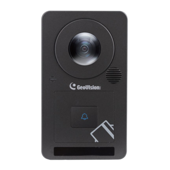
Page 7: Overview
Introduction 1.3 Overview Name Function Lens Receives image. Microphone Receives sound from GV-CS1320. Card Reader Reads ID cards or ID tags. IR LEDs Automatically illuminates for night time use. Speaker Talks to the surveillance area from the local computer. Touchpad and LED Touch to activate the talk mode. - Page 8 LED and Beeper Status Condition Beeper Ready Blue (Connected to GV-ASManager) Purple (Disconnected from GV-ASManager) Access Denied Displays red LED Two short beeps momentarily Access Granted Displays green LED One long beep momentarily Touchpad activated Flashes blue momentarily One short beep Touchpad ignored Returns to blue/purple LED Three short beeps after 30...
-
Page 9: Installation
2. Place the mounting plate on the single gang power box and secure with the 2 standard screws provided. 3. Place GV-CS1320 on the mounting plate together with the single gang power box and thread the cables through the holes. -
Page 10: Connecting The Camera
2 readers. You need two power wires and two RS-485 wires from one reader to GV-CS1320. When connecting a second reader to GV-CS1320, you will need to set up a separate power source to power the second reader if the total power consumption (including output devices) exceeds 12V. -
Page 11: Connecting Network Readers
Light Red Button IN2 Brown IN COM Note: You can connect a GV-I/O Box to your GV-CS1320 to give an extra layer of security. For details, see Chapter 8 Connecting to GV-I/O Box 4 Ports, GV-CS1320 Camera Access Controller User’s Manual. -
Page 12: Connecting Output Devices
(+) point on the locking device to the Door COM wire on GV-CS1320, connect the two (-) points of the locking device and the external power supply together, and connect the (+) point on the external power supply to the Door NO or Door NC wire on GV-CS1320 based on the state of the locking device. -
Page 13: Connecting Gv-Cs1320 To Pc
Connecting GV-CS1320 3.5 Connecting GV-CS1320 to PC Connecting GV-CS1320 to a computer enables you to access its Web interface and connect it to GV-ASManager if the computer is installed with GV-ASManager. The computer running GV-ASManager software can be used to monitor the access information and alarm messages from GV-CS1320. -
Page 14: Connecting The Power
1. Power should only be applied to the unit when all connections are completed and tested. 2. GV-CS1320 produces an output voltage of 12V. You will need to connect an external power supply if the total power consumption exceeds 12V after readers and output... -
Page 15: Accessing The Gv-Fisheye Camera
4. Accessing GV-CS1320 4.1 Creating Login Credentials When purchasing a new GV-CS1320 or after loading default, you need to set up a login username and password for the GV-CS1320. Download and install GV-IP Device Utility from our website. On the GV-IP Device Utility window, click to search for your GV-CS1320. -
Page 16: Web Browser
4.2 Web Browser To access the functions and settings of GV-CS1320 on the Web interface, ensure your PC use one of the following web browsers. Browser Internet Explorer 9.x or later Firefox Google Chrome Safari Note: For users of non-IE browsers, download GV-Web Viewer to access full functioning... -
Page 17: Looking Up The Dynamic Ip Address And Logging In
4.3 Looking Up the Dynamic IP Address and Logging In By default, when GV-CS1320 is connected to LAN with a DHCP server, it is automatically assigned with a dynamic IP address. Follow the steps below to look up its IP address and log in the Web interface. -
Page 18: Configuring The Ip Address
4.4 Configuring the IP Address By default, GV-CS1320, connected to LAN without a DHCP server, is assigned with a static IP address of 192.168.0.10. Follow the steps below to assign a new IP address to avoid IP conflict with other GeoVision devices. -
Page 19: The Web Interface
Stops playing video. 3 Microphone Talks to the surveillance area from the local computer. 4 Speaker Listens to the audio around GV-CS1320. 5 Snapshot Takes a snapshot of live video. 6 File Save Records live video to the local computer. -
Page 20: Upgrading System Firmware
6. Upgrading System Firmware GeoVision periodically releases the updated firmware on the website. To load the new firmware into the GV-CS1320, follow the instructions below. 1. In the Live View window, click the Show System Menu button (No. 8, Chapter 5 The Web Interface) and select Remote Config. -
Page 21: Restoring To Factory Default
7. Restoring to Factory Default If for any reason the GV-CS1320 is not responding correctly, you can reset it to its factory default settings by using its Web interface or pressing the Default button on the unit. 7.1 Using the Web Interface 1.
Need help?
Do you have a question about the GV-CS1320 and is the answer not in the manual?
Questions and answers