GeoVision GV-AS100 User Manual
Hide thumbs
Also See for GV-AS100:
- Hardware installation manual (131 pages) ,
- Quick start manual (17 pages) ,
- Installation manual (172 pages)
Table of Contents
Advertisement
Quick Links
Download this manual
See also:
Installation Manual
Advertisement
Table of Contents

Related Manuals for GeoVision GV-AS100


Summary of Contents for GeoVision GV-AS100
- Page 1 GV-AS/EV Controller User’s Manual Before attempting to connect or operate this product, please read these instructions carefully and save this manual for future use. ASEV-J...
- Page 2 GeoVision. Every effort has been made to ensure that the information in this manual is accurate. GeoVision, Inc. makes no expressed or implied warranty of any kind and assumes no responsibility for errors or omissions. No liability is assumed for incidental or consequential damages arising from the use of the information or products contained herein.
-
Page 3: Table Of Contents
1. GV-AS100 / 1010 Controller ................. 1 1.1 Introduction ......................2 1.1.1 Main Features ....................4 1.1.2 Packing List....................5 1.1.3 GV-AS100 / 1010 Board Layout ..............6 1.2 Installation........................ 7 1.2.1 Connecting Card Readers................8 1.2.1.A Wiegand Readers (GV-AS100 Only) ............. 8 1.2.1.B RS485 Readers .................. - Page 4 1.3.6 Displaying System Information ..............29 1.3.7 Restoring Factory Defaults................30 1.4 Web-Based Configurations ..................31 1.5 GV-AS100 / 1010 Specifications ................32 2. GV-AS110 / 1110 Controller ................34 2.1 Introduction ......................35 2.1.1 Main Features ....................37 2.1.2 Packing List....................38 2.2 Installation.......................39 2.2.1 Connecting Card Readers................41 2.2.1.A Wiegand Readers (GV-AS110 Only) ............41...
- Page 5 3.3 Programming Mode....................69 3.3.1 Adding and Deleting Cards ................69 3.3.1.A Adding a Card..................70 3.3.1.B Deleting a Card..................70 3.4 LED Status and Beeper ..................71 3.5 Web-Based Configurations ..................72 3.6 GV-AS120 Specifications ..................73 4. GV-AS210 / 2110 / 2120 Controller ..............74 4.1 Introduction ......................75 4.1.1 Main Features ....................75 4.1.2 Packing List....................76...
- Page 6 5.2.4 Connecting Backup Battery................102 5.2.5 Connecting the Power ................102 5.2.6 Connecting the PC ..................103 5.3 Other Settings .......................104 5.3.1 Web Setting Switch ..................104 5.3.2 Resetting the GV-AS410 / 4110 / 810 / 8110..........104 5.3.3 Restoring Factory Defaults.................105 5.4 GV-AS410 / 4110 / 810 / 8110 Kit (Optional)............106 5.4.1 Packing List....................106 5.4.2 Overview....................107 5.4.3 Connecting the GV-AS410 / 4110 / 810 / 8110 Kit........108...
- Page 7 9.1.1 Main Features ....................171 9.1.2 Packing List....................171 9.1.3 GV-ASBox Board Layout................172 9.1.4 Installation....................173 9.1.4.A Connecting GV-AS100 / 110 / 120............173 9.1.4.B Connecting a Wiegand Reader............174 9.1.4.C Connecting GV-Readers and GV-GF Fingerprint Readers ....175 9.1.4.D Connecting Input Devices..............176 9.1.4.E Connecting Output Devices ..............177 9.1.4.F Connecting Backup Battery..............179...
- Page 8 9.2.4 Installation....................184 9.2.4.A Connecting GV-AS100 / 110 / 120............184 9.2.4.B Connecting GV-Readers and GV-GF Fingerprint Readers ....185 9.2.4.C Connecting Backup Battery ..............186 9.2.4.D Other Settings ..................187 9.2.4.D.a Web Setting Switch................187 9.2.4.D.b Restoring Factory Defaults..............187 9.2.4.D.c Power Status LED................187 9.2.5 GV-ASNet Specifications ................188 9.3 Web Interface through Optional Devices ...............189...
-
Page 9: Welcome
This user manual includes the following types of GV-AS / GV-EV Controllers: GV-AS Controllers Doors Supported Page Number One-Way Control Two-Way Control GV-AS100 / 1010 See p. 1 GV-AS110 / 1110 See p. 34 GV-AS120 See p. 59 2 (Wiegand only) GV-AS210 / 2110 / See p. -
Page 10: Important Notes For Maintaining Power Supply
Replaceable Button Cell (GV-AS100 / 2110 / 2120 / 4110 / 8110) For GV-AS100 / 2110 / 2120 / 4110 / 8110, you can replace the battery on your own when you see low battery messages and icons in GV-ASManager. - Page 11 Note: Make sure the plastic insulation film under the battery is removed when using GV- AS100 / 2110 / 2120 / 4110 / 8110 for the first time. The low battery messages and icons will appear if the plastic film is not removed. Built-in Battery (GV-AS1010 / 110 / 1110 / 120 / 210 / 410 / 810 &...
-
Page 12: Elevator Control
GV-AS / GV-EV Controllers provide two types of elevator control. For GV-AS100 / 1010 / 110 / 1110 / 120 / 210 / 2110 / 2120 / 410 / 4110 / 810 / 8110, the GV-AS Controller can control access to the elevator call buttons. Users who present the correct identification card to the elevator reader will be able to use the elevator and can go any floors. -
Page 13: Optional Devices
GV-DFR1352 RS-485 outputs, the unit can be connected to any standard access control panel. Only works with GV-AS100 / 110 / 120. The device can add Network GV-ASBox function, 1 Wiegand interface, 8 additional inputs and outputs to GV- AS100, GV-AS110 and GV-AS120. - Page 14 RS-232 signal of one controller to RS-485, allowing the controller to connect to a computer. Only works with GV-AS100 / 110 / 120. GV-Net / IO Card can convert the GV-Net / IO standard RS-232 signal of one controller to RS-485, allowing the controller Card to connect to a computer.
- Page 15 Only works with GV-AS2120. The GV-POE Switch is designed to provide power along with network connection for IP devices. The GV-POE Switch GV-POE Switch is available in various models with different numbers and types of ports. GV-AS2120 requires PoE that provides at least 25.5 W (IEEE 802.3at). Power Adapter Contact your sales representative for the countries and areas supported.
-
Page 16: Installation Considerations
1968.50 ft). There is no need to use additional power when the distance is within 30.48 meters (100 ft). For GV-AS100 / 2110 / 2120 / 4110 / 8110, it is highly recommended to replace the button cell battery included on the circuit board annually. -
Page 17: Firmware And Software Compatibility
The GV-AS / GV-EV Controllers firmware versions compatible with GV-ASManager V4.2.1 - V4.4.3 are listed below. GV-ASManager Models V4.2.1 V4.2.2 V4.2.3 V4.3 V4.4 V4.4.1 V4.4.2 V4.4.3 GV-AS100 V1.08 GV-AS110 / 120 V1.07 GV-AS200 V2.02 GV-AS200 V2.01 Ethernet Module GV-AS400 V1.06 GV-AS1010 V1.0... -
Page 18: Definition
Definition Tampering Alarm GV-AS100 / 1010 / 110 / 1110 / 120 have built-in sensors to detect whether the controller is being physically tampered with (i.e. opening of the controller or sustaining strong impact). For GV-AS210 / 2110 / 2120 / 410 / 4110 / 810 / 8110, the tampering alarm sensor needs to be installed separately and the triggering conditions depend on the type of sensor installed. -
Page 19: Gv-As100 / 1010 Controller
1. GV-AS100 / 1010 Controller... -
Page 20: Introduction
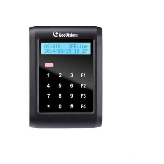
1.1 Introduction GV-AS100 / 1010 is a single door controller with a built-in a card reader and a LCD display. You can connect one more card reader to GV-AS100, and up to two more card readers to GV-AS1010 for entry and exit applications. GV-AS100 / 1010 has the capability to store up to one thousand cards as a standalone model and up to 40,000 cards when connected to GV-ASManager. - Page 21 GV-AS100 / 1010 Controller GV-AS100 can make network connection to GV-ASManager using the optional GV-ASBox or GV-ASNet. With GV-ASBox, two-door control is also possible as illustrated below. Figure 1-2 Through GV-ASBox Door GV-ASNet RS- 485 RS-485 GV-AS100 Wiegand / RS-485...
-
Page 22: Main Features
1.1.1 Main Features GV-AS100 1 door (one-way and two-way control), expandable to 2 doors with optional GV-ASBox 1,000 / 40,000 cards (standalone / networked or RS-485 mode) Easy programming from keypad Built-in 3 digital inputs and 2 relay outputs ... -
Page 23: Packing List
GV-AS100 / 1010 Controller 1.1.2 Packing List GV-AS100 GV-AS100 Power Adaptor 12V DC / 1A Power Cord Screw x 3 Screw Anchor x 2 Master Card GV-AS ID F Card x 20 ... -
Page 24: Gv-As100 / 1010 Board Layout
1.1.3 GV-AS100 / 1010 Board Layout GV-AS100 GV-AS1010 Figure 1-4... -
Page 25: Installation
GV-AS100 / 1010 Controller 1.2 Installation Open the GV-AS100 / 1010 to access the terminal block. GV-AS100 Pin Function Function 19 Door NO 18 Door NC 12V Power Sensor IN1 17 Door COM Button IN2 16 Alarm NO RS-485 A+ for ASBox / ASNet... -
Page 26: Connecting Card Readers
GV-AS100 provides one Wiegand input for connection of the Wiegand reader ranging from 26 to 64 bits. Through the GV-AS100 keypad, you can set the Wiegand reader as the entry or exit reader. To define the reader, see the AS100 Function option in 1.3.5 Setting Parameters. -
Page 27: B Rs485 Readers
1.2.1.B RS485 Readers For long-distance connection and non-Wiegand card readers, you can establish RS-485 connection with any GV-Readers and GV-GF1911 / 1912. GV-AS100 can connect with 1 reader through RS-485 connection. GV-AS1010 can connect with up to 2 readers through a single RS-485 cable. -
Page 28: C Network Readers (Gv-As1010 Only)
1.2.1.C Network Readers (GV-AS1010 Only) GV-AS1010 supports network connection with GV-CR420 and GV-GF1921 / 1922. Through the GV-AS1010 keypad, you can set the network reader as the entry or exit reader. To define the reader, see the Door/Gate Function option in 2.3.2 Programming the GV-AS110 / 1110. -
Page 29: Connecting Input Devices
All inputs are dry contact and can be configured as normally open (NO) or normally closed (NC) through the GV-AS100 / 1010 keypad. The default value is NO. To change the input status, see the Set Contact Type option in 1.3.5 Setting Parameters. -
Page 30: Connecting Output Devices
1.2.3 Connecting Output Devices GV-AS100 supports 2 types of outputs: 1. Alarm outputs, e.g. siren or bell 2. Door outputs, e.g. electronic lock The table below shows the pin assignments of output connectors on GV-AS100 / 1010. GV-AS100 Pin Function Alarm COM... - Page 31 (-) points of the locking device and the external power supply together, and connect the (+) point on the external power supply to the Door NO or Door NC on GV-AS100 / 1010 based on the state of the locking device.
-
Page 32: Connecting The Pc
GV-ASManager if the computer is installed with GV-ASManager. GV- ASManager software can monitor the access information and alarm messages from GV- AS100 / 1010. The communication link between the computer and GV-AS100 / 1010 is as below. -
Page 33: A Connecting Gv-As100 To Pc
The figure below illustrates the RS-485 connection to the computer. For this connection, a RS-485 to RS-232 converter between GV-AS100 and the computer is required. You can use GV accessories, such as GV-Hub, GV-COM and GV-NET/IO Card, as the RS-485/RS-232 converter. -
Page 34: B Connecting Gv-As1010 To Pc
The figure below illustrates the network connection to the computer. For this connection, the optional product GV-ASBox or GV-ASNet is required. Figure 1-11 Connect two power wires and two RS-485 wires from GV-ASBox / GV-ASNet to GV-AS100. The table below shows the pin assignments of related connectors on GV-AS100. Pin Function... -
Page 35: C Switches (Gv-As100 Only)
The supplied power adaptor can be connected to any power source supplying from 100 to 240V. Using the supplied power cord and adaptor, connect GV-AS100 / 1010 to the power. Note: Power should only be applied to the unit when all connections are completed and... -
Page 36: Fitting The Battery
When the power in the battery becomes low, the message “Low Battery” will appear on GV-AS100 / 1010 LCD. In this case, replace the battery. All settings on GV- AS100 / 1010 will disappear about 10 hours after the battery stops working, and GV-AS100 / 1010 will be restored to default settings. -
Page 37: Using The Function Keys (Gv-As1010 Only)
GV-AS100 / 1010 Controller 1.2.7 Using the Function Keys (GV-AS1010 Only) GV-AS1010 comes with four function keys for time and attendance records. On the Web interface of GV-AS1010, you can define function keys. Refer to the Function Key section in Chapter 8. -
Page 38: Programming Mode
1.3 Programming Mode After powering on GV-AS100, you must create a Master Card first. It is required to present the Master Card and enter its PIN code every time before programming GV-AS100. For GV-AS1010, you must create two cards first, an Enroll Card and a Delete Card. The Enroll Card is used for adding new cards and the Delete Card is used for deleting cards. - Page 39 Restores GV-AS100 / 1010 to factory defaults. *837 (*TES) Tests numeral keys to see if they can be displayed properly. Before programming GV-AS100 / 1010, you also need to know the following keys. Function * Used to cancel the selection, or go back to the previous page.
-
Page 40: Quick Reference Of Programming Table
Quick Reference of Programming Table 1.3.1 GV-AS100 Card Manger Add New Card 1) N, 2) A, 3) B, 4) S Del Card Data Reset Card’s APB Display System Door’s Auth Mode Door’s Event ASBox Comm. State Memory’s State ID & IP Address... - Page 41 GV-AS100 / 1010 Controller GV-AS1010 Card Manger Reset Card’s APB Display System Door’s Auth Mode Door’s Event Memory’s State ID & IP Address Display Version Set Parameter Set Local Time Set AS1010 ID Set AS1010 IP Set Auth. Mode Auth. Schedule...
-
Page 42: Adding And Deleting A Card
2. The cards added through GV-ASManager cannot be deleted on GV-AS100 / 1010. 1.3.2.A Adding a Card Up to 1,000 cards can be enrolled on GV-AS100 / 1010 directly without additional software. When working with GV-ASManager, GV-AS100 / 1010 can support up to 40,000 cards. -
Page 43: B Deleting A Card
GV-AS100 / 1010 Controller 1.3.2.B Deleting a Card GV-AS100 1. Press the code *227 (*CAR). 2. Present the Master Card and enter its PIN code. The LCD displays Add New Card. 3. Press 0. The LCD displays Del Card Data. -
Page 44: Accessing The Security Mode
1.3.4 Accessing the Security Mode The security mode is used to arm GV-AS100 / 1010. In the arm mode, no cards can be granted access and no one can program the unit. Only the security card that is associated with a PIN code can be used to disarm the unit. -
Page 45: Setting Parameters
You can define the parameters of some features on GV-AS100 / 1010. IMPORTANT: Once connecting to GV-AS100 / 1010, GV-ASManager will load its parameters to GV-AS100 / 1010. That means some of the parameters you set up here may be overwritten by GV-ASManager later. - Page 46 Note: The Parking Entry Type and Parking Exit Type only work when the sensor input of Car Detection is activated. When the card is present but the sensor inputs are not activated, the message “No Car In Zone” will appear in the GV-AS100 / 1010’s LCD.
-
Page 47: Displaying System Information
65536. GV-AS100 / 1010 will overwrite the oldest events when the limit is reached. When GV-AS100 / 1010 is connected to GV-ASManager, the event data will be uploaded to the server and the buffer of GV-AS100 / 1010 will be cleared. ... -
Page 48: Restoring Factory Defaults
1.3.7 Restoring Factory Defaults The restore function is used to clear all configured options and cards from GV-AS100 / 1010 memory and bring back the unit to factory defaults. IMPORTANT: Restoring default settings will delete all cards enrolled on GV-AS100 / 1010. -
Page 49: Web-Based Configurations
GV-AS100 / 1010 Controller 1.4 Web-Based Configurations GV-AS100 Through GV-ASBox or GV-ASNet, GV-AS100 can communicate with GV-ASManager over the network. Using GV-ASBox or GV-ASNet, you can also access the Web interface of GV- AS100. Refer to Chapter 9 Optional Devices to see how to connect a GV-ASBox or GV-ASNet and how to access the Web interface of GV-AS100. -
Page 50: Gv-As100 / 1010 Specifications
1.5 GV-AS100 / 1010 Specifications GV-AS100 8-bit RISC microprocessor 1,000 / 40,000 cards (standalone / networked or RS- Number of User Cards 485 mode) 13.56 MHz for ISO14443A (Mifare DESFire, Mifare Frequency Plus and Mifare Classic) Event Buffer 65,536 events and log data... - Page 51 GV-AS100 / 1010 Controller GV-AS1010 32-bit ARM7TDMI Number of User Cards 1,000 / 40,000 cards (standalone / networked mode) 13.56 MHz for ISO14443A (Mifare DESFire, Mifare Plus Frequency and Mifare Classic) Event Buffer 65,536 events and log data Power 12V DC, 1.25A...
-
Page 52: Gv-As110 / 1110 Controller
2. GV-AS110 / 1110 Controller... -
Page 53: Introduction
GV-AS110 / 1110 Controller 2.1 Introduction GV-AS110 / 1110 is a single door controller with a built-in reader. You can connect one more card reader to GV-AS110 and up to two more card readers to GV-AS1110 for entry and exit applications. GV-AS110 comes with built-in RS-485 and Wiegand interface, while GV-AS1110 comes with TCP/IP network port. - Page 54 GV-AS110 can make network connection to GV-ASManager using the optional GV-ASBox or GV-ASNet. With GV-ASBox, two-door control is also possible as illustrated below. Door Door RS-485 GV-AS110 Wiegand / RS-485 Wiegand Reader Reader (x4) GV-ASBox TCP/IP GV-ASManager Figure 2-2 Through GV-ASBox Door GV-ASNet RS- 485...
-
Page 55: Main Features
GV-AS110 / 1110 Controller 2.1.1 Main Features GV-AS110 1 door (one-way and two-way control), expandable to 2 doors with optional GV-ASBox 1,000 / 40,000 cards (standalone / networked or RS-485 mode) Easy programming from keypad Built-in 3 digital inputs and 2 relay outputs ... -
Page 56: Packing List
2.1.2 Packing List GV-AS110 GV-AS110 Power Adaptor 12V DC / 1.25A Power Cord Screw x 2 Screw Anchor x 2 Front Cover Plate x 2 Enroll Card Delete Card GV-AS ID F Card x 20 ... -
Page 57: Installation
GV-AS110 / 1110 Controller 2.2 Installation The wire assignment of the GV-AS110 cable data are illustrated below. Front View Figure 2-4 Rear View Wire color Definition 12V DC Black Green Wiegand Data 0 White Wiegand Date 1 Blue RS485+ Light Blue RS485- Yellow Door Sensor IN1... - Page 58 IN1 (Sensor) 7.5V~12V DC Purple IN2 (Button) Brown Door COM Yellow Door NC Black © 2014 GeoVision, Inc. All rights reserved. All GeoVision Products are made in Taiwan. Orange Door NO Green IN COM Blue IN1 (Sensor) Purple IN2 (Button)
-
Page 59: Connecting Card Readers
GV-AS110 / 1110 Controller 2.2.1 Connecting Card Readers 2.2.1.A Wiegand Readers (GV-AS110 Only) GV-AS110 provides one Wiegand input for connection to the Wiegand reader ranging from 26 to 64 bits. Through the GV-AS110 keypad, you can set the Wiegand reader as the entry or exit reader. -
Page 60: Connecting Input Devices
2.2.2 Connecting Input Devices GV-AS110 supports 3 types of inputs, while GV-AS1110 supports 2 types of inputs. 1. GV-AS110 / 1110: Sensor inputs, e.g. door status sensor 2. GV-AS110 / 1110: Button inputs, e.g. door opener 3. GV-AS110 only: Fire Sensor inputs, e.g. fire detector All inputs are dry contact and can be configured as normally open (NO) or normally closed (NC) through the keypad. -
Page 61: Connecting Output Devices
GV-AS110 / 1110 Controller 2.2.3 Connecting Output Devices GV-AS110 supports 2 types of outputs, while GV-AS1110 supports 1 type of output: 1. GV-AS110 only: Alarm outputs, e.g. siren or bell 2. GV-AS110 / 1110: Door outputs, e.g. electronic lock The table below shows the wire assignments of output connectors on GV-AS110 and GV- AS1110. - Page 62 To connect an output device: The example below illustrates the connection of a locking device to GV-AS110 / 1110. Connect the (+) point on the locking device to the Door COM wire on GV-AS110 / 1110, connect the two (-) points of the locking device and the external power supply together, and connect the (+) point on the external power supply to the Door NO or Door NC wire on GV- AS110 / 1110 based on the state of the locking device.
-
Page 63: Connecting To The Pc
GV-AS110 / 1110 Controller 2.2.4 Connecting to the PC Connecting GV-AS110 / 1110 to a computer allows you to access its Web interface and connect it to GV-ASManager if the computer is installed with GV-ASManager. The computer running GV-ASManager software can be used to monitor the access information and alarm messages from the controller. -
Page 64: B Connecting Gv-As1110 To Pc
RS485 + Light Blue RS485 - See 9.1.4.A Connecting GV-AS100 / 110 / 120 or 9.2.4.A Connecting GV-AS100 / 110 / 120 to see how to connect to GV-ASBox or GV-ASNet. 2.2.4.B Connecting GV-AS1110 to PC The figure below illustrates the network connection between GV-AS1110 and the computer. -
Page 65: Connecting The Power
GV-AS110 / 1110 Controller 2.2.5 Connecting the Power The supplied AC adaptor can be connected to any power source supplying from 100 to 240V. Connect 12V and GND wires to the supplied power adapter and then connect the power adapter to a power source. The table below shows the pin assignments of the power connectors on GV-AS110 and GV-AS1110. -
Page 66: Programming Mode
2.3 Programming Mode After powering on GV-AS110 / 1110, you must create two cards first, an Enroll Card and a Delete Card. The Enroll Card is used for adding new cards and the Delete Card is used for deleting cards. Either card will allow you to program the various configurations on GV-AS110 / 1110. -
Page 67: A Adding A Card
GV-AS110 / 1110 Controller 2.3.1.A Adding a Card Up to 1,000 cards can be enrolled on GV-AS110 / 1110 directly without needing additional software. When working with GV-ASManager software, GV-AS110 / 1110 can support up to 40,000 cards. 1. Present the Enroll Card. 2. -
Page 68: B Deleting A Card
2.3.1.B Deleting a Card 1. Present the Delete Card. 2. Present the card you want to delete. 3. The GV-AS110 / 1110 will produce a long beep if the card has been deleted successfully and three short beeps if the deleting procedure has failed. -
Page 69: Programming The Gv-As110 / 1110
GV-AS110 / 1110 Controller 2.3.2 Programming the GV-AS110 / 1110 The command codes used to program various functions on GV-AS110 / 1110 are listed below. All command codes will start with an asterisk * to clear all previous commands and end with a number sign # to send the command. - Page 70 *723_ _ _ _# Set Alarm For the first blank digit, enter a number from Event options 0 to 4. For the second blank digit, type 1 Held Open 0 to enable the option and 0 to disable the option. Forced Open ...
- Page 71 GV-AS110 / 1110 Controller For example, to enable the Fixed Card + PIN mode, press *5264#. *_ _ _ _ _ _ _ _(_ _ _ _)# Open door To open the door without presenting a card, enter with card the 8-digit card number on the back of the Enter the 8-digit card number and...
-
Page 72: Led Status And Beeper
2.4 LED Status and Beeper Normally, the LED on GV-AS110 / 1110 is blue during standby mode. The LED status and beeper under different conditions are listed below. GV-AS110 Condition Beeper Card + PIN Code Mode Flashes blue Silent Card Mode Constant blue Silent Release Mode... - Page 73 GV-AS110 / 1110 Controller GV-AS1110 Condition Beeper Access Granted Flashes green momentarily One long beep Access Denied Flashes yellow momentarily Three short beeps Enroll Card Flashes green / purple momentarily One long beeps Delete Card Flashes yellow / purple momentarily One long beeps All alarms Flashes yellow momentarily...
-
Page 74: Web-Based Configurations
2.5 Web-Based Configurations GV-AS110 Through GV-ASBox or GV-ASNet, GV-AS110 can communicate with GV-ASManager over the network. Using GV-ASBox or GV-ASNet, you can also access the Web interface of GV- AS110. Refer to Chapter 9 Optional Devices to see how to connect a GV-ASBox or GV-ASNet and how to access the Web interface of GV-AS110. -
Page 75: Gv-As110 / 1110 Specifications
GV-AS110 / 1110 Controller 2.6 GV-AS110 / 1110 Specifications GV-AS110 32-bit RISC microprocessor 1,000 / 40,000 cards (standalone / networked or RS- Number of User Cards 485 mode) 13.56 MHz for ISO14443A (Mifare DESFire, Mifare Frequency Plus and Mifare Classic) Event Buffer 65,536 events and log data Power... - Page 76 GV-AS1110 32-bit ARM7TDMI Number of User Cards 1,000 / 40,000 cards (standalone / networked mode) 13.56 MHz for ISO14443A (Mifare DESFire, Mifare Plus Frequency and Mifare Classic) Event Buffer 65,536 events and log data Power 12V DC, 1.25A TCP/IP Interface 1 TCP/IP interface for GV-CR420 and GV-GF1921 / 1922 Communication Protocol TCP/IP...
-
Page 77: Gv-As120 Controller
3. GV-AS120 Controller... -
Page 78: Introduction
3.1 Introduction Working as a standalone solution, GV-AS120 is a card reader and also a single door controller. It is possible to add one more card reader to GV-AS120 for entry and exit applications. GV-AS120 has the capability to store up to one thousand cards. Programming of GV-AS120 is done from the software GV-ASManager through the RS-485 connection. - Page 79 GV-AS120 Controller GV-AS120 can make network connection to GV-ASManager using the optional GV-ASBox or GV-ASNet. With GV-ASBox, two-door control is also possible as illustrated below. Figure 3-2 Through GV-ASBox Figure 3-3 Through GV-ASNet...
-
Page 80: Main Features
3.1.1 Main Features 1 door (one-way and two-way control), expandable to 2 doors with optional GV-ASBox 1,000 / 40,000 cards (standalone / networked or RS-485 mode) Built-in 2 digital inputs and 1 relay output 1 Wiegand output (26 ~ 64 bits) for extra reader programming ... -
Page 81: Installation
GV-AS120 Controller 3.2 Installation The wire assignment of the GV-AS120 cable data are illustrated below. Front View Rear View Figure 3-4 Wire color Definition Black Green Wiegand Data 0 White Wiegand Date 1 Blue RS485+ Light Blue RS485- Brown IN COM (GND) Yellow Door Sensor IN1 LRed... -
Page 82: Connecting A Wiegand Reader
3.2.1 Connecting a Wiegand Reader GV-AS120 provides one Wiegand input for connection to the Wiegand reader ranging from 26 to 64 bits. Through the Web interface of GV-AS120, you can set the Wiegand reader as the entry or exit reader. To define the reader, see 9.3.2.A Function Setting. The table below shows the wire assignments of the Wiegand input on GV-AS120. -
Page 83: Connecting Output Devices
GV-AS120 Controller 3.2.3 Connecting Output Devices GV-AS120 supports 1 type of output: Door outputs, e.g. electronic lock The table below shows the wire assignments of output connectors on GV-AS120. Wire color Definition Purple Door COM Orange Door NC Gray Door NO ... -
Page 84: Connecting To The Pc
3.2.4 Connecting to the PC The computer running GV-ASManager software can be used to monitor the access information and alarm messages from GV-AS120. The communication link between the computer and GV-AS120 can be either through RS-485 or network. For RS-485 connection, a RS-485 to RS-232 converter is required, such as a GV-Hub, GV-COM or GV-NET/ IO Card V3.1. - Page 85 GV-AS120 Controller To define ID number, control type and authentication mode Using the GV-AS120 Setting AP in the GV-ASManager folder, you can define the ID number of multiple GV-AS120 connected through RS-485 interface, as well as set the control type and authentication mode. Go to C:\Access Control\ASManager\ and double-click GV-AS120 SetupAP V100.exe.
-
Page 86: B Network Connection
RS485 A+ Light Blue RS485 A- See 9.1.4.A Connecting GV-AS100 / 110 / 120 or 9.2.4A Connecting GV-AS100 / 110 / 120 to see how to connect to GV-ASBox or GV-ASNet. 3.2.5 Connecting the Power The supplied AC adaptor can be connected to any power source supplying from 100 to 240V. -
Page 87: Programming Mode
GV-AS120 Controller 3.3 Programming Mode After powering on GV-AS120, you must create two cards first, an Enroll Card and a Delete Card. The Enroll Card is used for adding new cards and the Delete Card is used for deleting cards. Either card will allow you to program the various configurations on GV-AS120. Note: The card complying with ISO 14443A standard for smart card technology can be formatted as an Enroll Card or Delete Card. -
Page 88: A Adding A Card
3.3.1.A Adding a Card Up to 1,000 cards can be enrolled on GV-AS120 directly without needing additional software. When working with GV-ASManager software, GV-AS120 can support up to 40,000 cards. 1. Present the Enroll Card. 2. Present the card you want to add to the GV-AS120. 3. -
Page 89: Led Status And Beeper
GV-AS120 Controller 3.4 LED Status and Beeper Normally, the LED on GV-AS120 is blue during standby mode and the LED flashes green when a card is granted access or when the operation was successful. A red LED indicates access denied or the operation was unsuccessful. The LED status and beeper under different conditions are listed below. -
Page 90: Web-Based Configurations
3.5 Web-Based Configurations Through GV-ASBox or GV-ASNet, GV-AS120 can communicate with GV-ASManager over the network. Using GV-ASBox or GV-ASNet, you can also access the Web interface of GV- AS120. Refer to Chapter 9 Optional Devices to see how to connect a GV-ASBox or GV-ASNet and how to access the Web interface of GV-AS120. -
Page 91: Gv-As120 Specifications
GV-AS120 Controller 3.6 GV-AS120 Specifications 32-bit RISC microprocessor 1,000 / 40,000 cards (standalone / networked or RS- Number of User Cards 485 mode) 13.56 MHz for ISO14443A (Mifare DESFire, Mifare Frequency Plus and Mifare Classic) Event Buffer 65,536 events and log data Power 12V DC, 1.25A 1 Wiegand interface, 26 ~ 64 bit format... -
Page 92: Gv-As210 / 2110 / 2120 Controller
4. GV-AS210 / 2110 / 2120 Controller... -
Page 93: Introduction
GV-AS210 / 2110 / 2120 Controller 4.1 Introduction 4.1.1 Main Features One-way control: 4 doors Two-way control: 2 doors by Wiegand only; 4 doors by Wiegand / network; 4 doors with max 2 doors by Wiegand and other doors by RS-485 / network ... -
Page 94: Packing List
4.1.2 Packing List GV-AS210 / 2110 GV-AS210 / 2110 Power Adaptor 12V DC / 3A Power Cord Battery Cable Screw x 4 Micro SD Card 2 GB Software CD Warranty Card GV-AS2120 ... -
Page 95: Board Layout
GV-AS210 / 2110 / 2120 Controller 4.1.3 Board Layout GV-AS210 / 2110 Figure 4-1... - Page 96 GV-AS2120 Power Jack com.A RTC Battery com.A GV-AS2120 Battery com.B com.B RS-485_A TERM RS-485_B TERM Reader Connection Default Ethernet Figure 4-2...
-
Page 97: Installation
GV-AS210 / 2110 / 2120 Controller 4.2 Installation 4.2.1 Connecting Card Readers GV-AS210 / 2110 / 2120 can physically connect to card readers through its RS-485 and Wiegand interfaces. Wiegand: Compatible with any Wiegand card readers of 26 to 64 bits. ... -
Page 98: B Rs-485 Readers
4.2.1.B RS-485 Readers For long-distance connection and non-Wiegand card readers, you can establish RS-485 connection with any GV-Readers and GV-GF Fingerprint Readers. Up to 8 readers can be connected together with a single RS-485 cable to the RS-485 interface on GV-AS210 / 2110 / 2120. -
Page 99: Connecting Input Devices
GV-AS210 / 2110 / 2120 Controller 4.2.2 Connecting Input Devices Up to 8 input devices can be connected to GV-AS210 / 2110 / 2120. Connect the input wires to DI1~8 and connect GND wires to com.A or com.B. Multiple GND wires can be connected to the same com.A/B interface. -
Page 100: Connecting Output Devices
4.2.3 Connecting Output Devices Up to 8 output devices can be connected to GV-AS210 / 2110 / 2120. Check if your output device meets the following absolute maximum ratings before connecting it to outputs 1 ~ 8. Breakdown Voltage 110V AC ~ 250V AC, 30V DC Continuous Load Current 3A (AC), 3A (DC) Note: Absolute Maximum Ratings are those values beyond which damage to GV-... - Page 101 GV-AS210 / 2110 / 2120 Controller Note: If you want to use the power outputs on the GV-AS Controller, note that the maximum current of the individual voltage output is 12V, 0.9A.
-
Page 102: Connecting Backup Battery
4.2.4 Connecting Backup Battery You can connect any 12 V battery to the controller to provide backup power when the main power supply fails. When the main power supply is removed and the battery voltage level is above 10.2V, the battery will support normal operation of the controller. 12V Battery Power Jack Battery... -
Page 103: Connecting The Power
GV-AS210 / 2110 / 2120 Controller 4.2.5 Connecting the Power For GV-AS210 / 2110, you can connect the controller to power directly using the supplied 12V DC adaptor. For GV-AS2120, you can choose to supply power using a power adaptor (available for separate purchase) or using a Power over Ethernet (PoE) adapter. - Page 104 GV-AS2120: Connect a PoE adapter or a 12V DC / 3A power adapter (not included). When using PoE: The Ethernet cable must be Cat 5e or above. The maximum power consumption supported is 25.5 W. You will need to connect an external power supply if the total power consumption exceeds 25.5 W after output devices and readers are connected.
-
Page 105: Connecting The Pc
GV-AS210 / 2110 / 2120 Controller 4.2.6 Connecting the PC Connecting the controller to a computer allows you to access its Web interface and connect it to GV-ASManager if the computer is installed with GV-ASManager. The computer running GV-ASManager software can be used to monitor the access information and alarm messages from GV-AS210 / 2110 / 2120. -
Page 106: Fitting The Battery (Gv-As2110 / 2120 Only)
4.2.7 Fitting the Battery (GV-AS2110 / 2120 Only) GV-AS2110 / 2120 includes a replaceable cell button battery. When the power in the battery becomes low, a “Low Battery” message and icon will appear in GV-ASManager. When this happens, replace the battery. All settings on GV-AS2110 / 2120 will disappear about 10 hours after the battery stops working, and GV-AS2110 / 2120 will be restored to default settings. -
Page 107: Other Settings
GV-AS210 / 2110 / 2120 Controller 4.3 Other Settings 4.3.1 Web Setting Switch When the Web Setting switch is set to the ON position, you can modify Advanced Settings and Extended Reader of GV-AS210 / 2110 / 2120 through its Web interfaces. When the switch is set to the OFF position, Advanced Settings are not accessible. -
Page 108: Restoring Factory Defaults
4.3.3 Restoring Factory Defaults To restore GV-AS210 / 2110 / 2120 to factory default settings, press the Default button for 10 seconds. Power Jack GV-AS210 / 2110 Load Default Button Figure 4-14 Figure 4-15... -
Page 109: The Web Interface
GV-AS210 / 2110 / 2120 Controller 4.4 The Web Interface You can install GV-AS210 / 2110 / 2120 on a network and configure the controller through its Web interface. Refer to Chapter 7 Installing on a Network for detailed instructions on setting a fixed or dynamic IP address to access the controller. -
Page 110: Gv-As210 / As2110 / As2120 Specifications
GV-AS210: Distance 30 m (98.43 ft), 24 AWG Wiegand Interface GV-AS2110 / 2120: Distance 100 m (328.1), 24 AWG 12V DC power supply, 200mA TCP/IP Interface 1 TCP/IP interface for GeoVision network readers Communication Protocol TCP/IP Battery Built-in battery Replaceable button cell... -
Page 111: Gv-As410 / 4110 / 810 / 8110 Controller
5. GV-AS410 / 4110 / 810 / 8110 Controller... -
Page 112: Introduction
5.1 Introduction 5.1.1 Main Features GV-AS410 / 4110 One-way control: 4 doors Two-way control: 4 doors Support 8 Wiegand card readers of 26 to 64 bits Support 8 GV-Readers / GV-GF Fingerprint Readers through RS485 connection / Network ... -
Page 113: Packing List
GV-AS410 / 4110 / 810 / 8110 Controller 5.1.2 Packing List GV-AS410 / 4110 / 810 / 8110 GV-AS410 / 4110: Power Adaptor 12V DC / 3.5A GV-AS810 / 8110: Power Adaptor 12V DC / 5A Power Cord ... - Page 114 5.1.3 GV-AS410 / 4110/ 810 / 8110 Board Layout Figure 5-1...
-
Page 115: Installation
GV-AS410 / 4110 / 810 / 8110 Controller 5.2 Installation 5.2.1 Connecting Card Readers GV-AS410 / 4110 / 810 / 8110 supports two types of card reader interfaces: Wiegand: Compatible with any Wiegand card readers of 26 to 64 bits. ... -
Page 116: B Rs-485 Readers
5.2.1.B RS-485 Readers For long-distance connection and non-Wiegand card readers, you can connect RS-485 connection with any GV-Readers and GV-GF Fingerprint Readers. Using a single RS-485 cable, up to 8 readers can be connected together with to the RS-485 A+ / A- interface. For GV-AS810 / 8110, another 8 readers can be connected to the RS-485 B+ / B- interface, for a total of 16 RS-485 readers. - Page 117 GV-AS410 / 4110 / 810 / 8110 Controller Note: Each set of 12V power output and GND can provide power for up to 2 readers. The 3 sets on the power terminal can support up to 6 readers. If you wish to connect more readers and the Wiegand interfaces are already occupied, you can connect the readers to external power source.
-
Page 118: Connecting Input Devices
5.2.2 Connecting Input Devices Up to 16 input devices can be connected to GV-AS410 / 4110 / 810 / 8110. Connect the input wires to IN1~16 and connect GND wires to GND. Multiple GND wires can be connected to the same GND pin. All inputs are dry contact that can be configured as normally open (NO) or normally closed (NC) on the Web interface. -
Page 119: Connecting Output Devices
GV-AS410 / 4110 / 810 / 8110 Controller 5.2.3 Connecting Output Devices Up to 24 output devices can be connected to GV-AS410 / 4110 / 810 / 8110. Check if your output device meets the following absolute maximum ratings before connecting it to output terminal block. -
Page 120: Connecting Backup Battery
5.2.4 Connecting Backup Battery You can connect any 12V battery to GV-AS410 / 4110 / 810 / 8110 to provide backup power when the main power supply fails. When the main power supply is removed and the battery voltage level is above 10.2V, the Discharging LED will light and the battery will support normal operation of the GV-AS410 / 4110 / 810 / 8110. -
Page 121: Connecting The Pc
GV-AS410 / 4110 / 810 / 8110 Controller 5.2.6 Connecting the PC Connecting GV-AS410 / 4110 / 810 / 8110 to a computer allows you to access its Web interface and connect it to GV-ASManager if the computer is installed with GV-ASManager. The computer running GV-ASManager software can be used to monitor the access information and alarm messages from GV-AS410 / 4110 / 810 / 8110. -
Page 122: Other Settings
5.3 Other Settings 5.3.1 Web Setting Switch When the Web Setting switch is set to the ON position, you can modify Advanced Settings and Extended Reader settings of GV-AS410 / 4110 / 810 / 8110 through its Web interfaces. When the switch is set to the OFF position, Advanced Settings and Extended Reader settings are not accessible. -
Page 123: Restoring Factory Defaults
GV-AS410 / 4110 / 810 / 8110 Controller 5.3.3 Restoring Factory Defaults To restore GV-AS410 / 4110 / 810 / 8110 to factory default settings, press the Default button for 10 seconds. Figure 5-11... -
Page 124: Gv-As410 / 4110 / 810 / 8110 Kit (Optional)
5.4 GV-AS410 / 4110 / 810 / 8110 Kit (Optional) GV-AS410 / 4110 / 810 / 8110 Kit is a cabinet containing a GV-AS410, GV-AS4110, GV- AS810 or GV-AS8110, a power adapter board, a power supply and a casing for backup battery. -
Page 125: Overview
GV-AS410 / 4110 / 810 / 8110 Controller 5.4.2 Overview GV-AS410 / 4110 / 810 / 8110 Kit Power Adapter Board Casing for Backup Battery Power Supply (US or EU standard) Figure 5-12... -
Page 126: Connecting The Gv-As410 / 4110 / 810 / 8110 Kit
5.4.3 Connecting the GV-AS410 / 4110 / 810 / 8110 Kit Up to 8 output devices can be powered by the power adapter board. Connect each output device to one terminal block on the board. Connect the COM pin on GV-AS410 / 4110 / 810 / 8110’s output terminal block to the corresponding pin on the power adapter board. - Page 127 GV-AS410 / 4110 / 810 / 8110 Controller Connect the ED + / - pins to the (+) and (-) points on the output device (ex: electric lock). GV-AS410 / 4110 / 810 / 8110 Output Device ED - NC / NO Power Adapter Board ED - NC / NO...
-
Page 128: Gv-As410 / 4110 / 810 / 8110 Kit Specifications
6.4.4 GV-AS410 / 4110 / 810 / 8110 Kit Specifications Power Adapter Board DC Voltage Range Output Rated Current 0.9A Rated Power 10.8 W Input Number of connectors Output Wire Size (AWG) 12 - 22 Power Supply DC Voltage Range Rated Current 12.5A Output... -
Page 129: The Web Interface
GV-AS410 / 4110 / 810 / 8110 Controller 5.5 The Web Interface You can install GV-AS410 / 4110 / 810 / 8110 on a network and configure GV-AS410 / 4110 / 810 / 8110 through its Web interface. Refer to Chapter 7 Installing on a Network for detailed instructions on setting up a fixed or dynamic IP address to access GV-AS410 / 4110 / 810 / 8110. -
Page 130: Gv-As410 / 4110 / 810 / 8110 Specifications
8 Wiegand interfaces, 26 ~ 64 bit format Distance 30 m (98.43 ft), 24 Distance 100 m (328.1), 24 Wiegand Interface 12V DC power supply, 200mA TCP/IP Interface 1 TCP/IP interface for GeoVision network readers Communication Protocol TCP/IP Battery Built-in battery Replaceable button cell... - Page 131 8 Wiegand interfaces, 26 ~ 64 bit format Distance 30 m (98.43 ft), 24 Distance 100 m (328.1), 24 Wiegand Interface 12V DC power supply, 200mA TCP/IP Interface 1 TCP/IP interface for GeoVision network readers Communication Protocol TCP/IP Battery Built-in battery Replaceable button cell...
-
Page 132: Gv-Ev48 Controller
6. GV-EV48 Controller... -
Page 133: Introduction
GV-EV48 Controller 6.1 Introduction GV-EV48 is an elevator controller designed to control access of 1 elevator with a maximum of 48 floors. Up to 2 GV-Readers / GV-GF Fingerprint Readers can be connected to GV- EV48 using RS-485 connection and network connection. GV-EV48 can recognize identification cards and grant access to the authorized floors only. - Page 134 6.1.3 GV-EV48 Board Layout Figure 6-1...
-
Page 135: Installation
GV-EV48 Controller 6.2 Installation 6.2.1 Connecting RS-485 Card Readers With a single RS-485 cable, you can connect up to 2 GV-Readers and / or GV-GF Fingerprint Readers to the RS-485 interface on GV-EV48. Figure 6-2 To connect to GV-CR420 or GV-GF1921 / 1922 through network connection, refer to 8.3.1 Extended Reader for details. -
Page 136: Connecting Output Relay
6.2.2 Connecting Output Relay Up to 24 output relays can be connected to the GV-EV48-24 Floors to control up to 24 elevator floors. Up to 48 output relays can be connected to the GV-EV48-48 Floors to control up to 48 elevator floors. Each output relay is set to control access to a corresponding floor in the elevator. -
Page 137: Connecting Backup Battery
GV-EV48 Controller 6.2.3 Connecting Backup Battery Using the supplied battery cable, you can connect any 12V battery to GV-EV48 to provide backup power when the main power supply fails. When the main power supply is removed and the battery voltage level is above 10.2V, the Discharging LED will light and the battery will support normal operation of the GV-EV48. -
Page 138: Connecting The Pc
6.2.5 Connecting the PC Connecting GV-EV48 to a computer allows you to access its Web interface and connects it to GV-ASManager if the computer is installed with GV-ASManager. The computer running GV-ASManager software can be used to monitor access information from GV-EV48. If connection with GV-ASManager is interrupted, GV-EV48 stores this information on the supplied micro SD card. -
Page 139: Other Settings
GV-EV48 Controller 6.3 Other Settings 6.3.1 Web Setting Switch When the Web Setting switch is set to the ON position, you can modify Advanced Settings and Extended Reader settings of GV-EV48 through its Web interfaces. When the switch is set to the OFF position, Advanced Settings and Extended Reader settings are not accessible. -
Page 140: Restoring Factory Defaults
6.3.3 Restoring Factory Defaults To restore GV-EV48 to factory default settings, press the Default button for 10 seconds. Figure 6-9... -
Page 141: The Web Interface
GV-EV48 Controller 6.4 The Web Interface You can install GV-EV48 on a network and configure GV-EV48 through its Web interface. Refer to Chapter 7 Installing on a Network for detailed instructions on setting up a fixed or dynamic IP address to access GV-EV48. Refer to Chapter 8 The Web Interface for details on the setup pages of the Web interface. -
Page 142: Gv-Ev48 Specifications
Power 12V DC, 3A 1 RS-485 interface only for GV-Readers and GV-GF RS-485 Interface Fingerprint Readers (max. 2 readers) TCP/IP Interface 1 TCP/IP interface for GeoVision network readers Communication Protocol TCP/IP Battery Built-in battery GV-EV48-24 Floors 24 relay outputs (30V DC, 1A; 125V AC, 0.3A) -
Page 143: Installing On A Network
7. Installing on a Network... - Page 144 GV-AS / GV-EV Controller to GV-ASManager for more comprehensive management. Note: To access the Web interface of GV-AS100 / 110 / 120 and allow communication with GV-ASManager over the network, a GV-ASBox or GV-ASNet is required. Refer to Chapter 9 Optional Devices for more details.
-
Page 145: Fixed Ip Connection
Installing on a Network 7.1 Fixed IP Connection If your network environment supports a static IP address, the wiring is illustrated as below: Figure 7-1 To assign the GV-AS / GV-EV Controller to a fixed IP: 1. Open an Internet browser, and type the default IP address https://192.168.0.100. This dialog box appears. - Page 146 2. Type the default value admin for both User name and Password, and click OK. This page appears. Figure 7-3 3. In the DHCP Client section, click Disable. Type the static IP address information, including IP Address, Subnet Mask, Default Gateway and Domain Name Server. 4.
-
Page 147: Dhcp Connection
Dynamic Network Services Inc. (DynDNS). 7.2.1 Connection over LAN GeoVision’s GV LocalDDNS Server can map the changing IP address of your controller to a device name, allowing you to access the controller using the device name. The Local DDNS Server can be installed in either GV-ASManager or a separate computer. - Page 148 Installing LocalDDNS Server To install the LocalDDNS Server in a computer, download GV-Local DDNS Service from http://www.geovision.com.tw/english/5_8_AS.asp under the Supplemental Utilities section. Follow the on-screen instructions to install the application. After Installation, the program will be minimized to the system tray.
- Page 149 Installing on a Network 5. In the Device Name field, keep the default setting or change it to match that of the GV- ASManager. 6. Click Submit to send the information to the LocalDDNS Server. When the setting is complete, the Status field will indicate: Register Success. Then the controller can be accessed with the device name.
-
Page 150: Connection Over Internet
Figure 7-7 Registering a DDNS Domain Name Note that the interface may vary slightly for GeoVision DDNS Server V1 and V2. To obtain a domain name from the GeoVision DDNS Server: 1. Click the GeoVision DDNS button on the Network Configuration page (Figure 7-5). Or open an Internet browser, and type the Web address http://ns.dipmap.com/register.aspx. - Page 151 Installing on a Network 2. In the Username field, type a name. Username can be up to 16 characters with the choices of “a ~ z”, “0 ~9”, and “-”. Note that space or “-” cannot be used as the first character.
- Page 152 3. Click Enable, and select Send to DDNS. 4. Type Host Name, User Name and Password that are registered on the DDNS Server. If you select GeoVision DDNS, the system will automatically bring up the Host Name. Figure 7-10 5. Click Submit. When the setting is complete, the Status field will indicate: Register...
-
Page 153: The Web Interface
8. The Web Interface... - Page 154 After installing the GV-AS / GV-EV Controller on the network, you can configure the controller settings on the Web interface. The left menu of the Web interface is divided into three sections: Basic Setting, Advanced Setting and Extended Device. The options available vary among different controller models.
-
Page 155: Basic Settings
The Web Interface 8.1 Basic Settings The Basic Settings section covers general system settings, firmware update and user account settings. For details on Network Setting, refer to Chapter 7 Installing on a Network. 8.1.1 System Setup In the left menu, click Other Configuration. This page appears. Figure 8-2... - Page 156 3DES Code 1-3: Stands for Triple DES (Data Encryption Standard). Type up to three different keys for data encryption. The default 3DES Code1 is 12345678. Device Port: Keeps the default value 4000. Or modify it to match that of GV-ASManager. ...
-
Page 157: Upgrading Firmware
The Web Interface 8.1.2 Upgrading Firmware Follow the steps below to update the firmware of the controller. 1. In the left menu, click Firmware Update. This page appears. Figure 8-3 2. Click the Browse… button to open the firmware file (*.bin) 3. -
Page 158: Changing Login Id And Password
8.1.3 Changing Login ID and Password To change the login ID and password: 1. In the left menu, click Security Configuration. 2. Modify the login name and password. The password is case sensitive and is limited to alphabets and numbers. Figure 8-5... -
Page 159: Advanced Settings
The Web Interface 8.2 Advanced Settings To configure the Advanced Setting on the Web interface, set the Web Setting switch on the GV-AS / GV-EV Controller to ON. See the Web Setting Switch section of each controller chapter. Under Advanced Settings, you can configure door/Wiegand settings, turn on Alarms, set the device time and edit the input/output functions. - Page 160 For GV-EV48, the options available in Advanced Settings page are fixed. Only the following setting pages are available: Figure 8-7...
-
Page 161: Function Configuration
The Web Interface 8.2.1 Function Configuration In the left menu, click Function Configuration. The number of door/gate settings or elevator settings available varies among different models. Figure 8-8 Note: For GV-EV48, only the ID and the Authentication Mode settings are available. - Page 162 [ID] Enter the ID number for the controller. This ID is used by GV-ASManager to differentiate among multiple units of controller. ID number can only be between 1 and 1000. [Door/Gate #] [Elevator] Select the function type and authentication mode for the use of the Doors/Gates. For GV- EV48, select an authentication mode to apply to all floors of the elevator.
- Page 163 The Web Interface [Series Function (APB & Fire)] This option lets you set the Anti-Passback function and fire sensor function across multiple door controllers. The Anti-Passback means that a card used on an entry door cannot access the same entry door again unless it has been used on a corresponding exit door. For details on setup, see Chapter 6 Anti-Passback on GV-ASManager User’s Manual.
-
Page 164: Parameter Configuration
8.2.2 Parameter Configuration In the left menu, click Parameter Configuration for GV-AS Controllers or click Elevator Parameter for GV-EV48. IMPORTANT: Once connected to GV-AS / GV-EV Controller, GV-ASManager will load its parameters to the controller. That means some of the Parameter Settings you have configured here may be overwritten by GV-ASManager later. - Page 165 The Web Interface [Interlock] When the option is enabled, the two mentioned doors will be interlocked, allowing only one door to be opened at a time. Note: The Interlock function is not available on the Web interface of GV-AS1010 / 1110 / 210 / 2110 / 2120 / 410 / 4110 / 810 / 8110.
- Page 166 When Elevator Control is selected in the Function Configuration page (Figure 8-8), these options become available: Option Description Relay on Time See the same option above. Fire Action Alarm Continuous See the same option above. Time [Alarm] Select Yes or No to enable or disable the alarm function. If you have defined the alarm conditions in the Input Configuration page (Figure 8-17), remember to activate the corresponding alarms here;...
- Page 167 The Web Interface When Parking Control is selected in the Function Configuration page (Figure 8-8), these options become available: Option Description Held Open See the same option above. Tamper Fire Alarm Access Denied When Elevator Control is selected in the Function Configuration page (Figure 8-8), these options become available: Option Description...
-
Page 168: B Gv-Ev48
8.2.2.B GV-EV48 The Parameter Configuration page allows you to specify which elevator floors are restricted. Figure 8-11... - Page 169 The Web Interface [Events] Relay On Time: Type a time period between 1-255 seconds. After access is granted by swiping a card or entering the password, the elevator button will remain accessible for the time period specified. After the specified time period, the elevator buttons for restricted floors will be locked again.
-
Page 170: Card Configuration
8.2.3 Card Configuration In the left menu, click Card Configuration to set the built-in card reader of GV-AS1010 and GV-AS1110 to read UID (unique identification) or GID (GeoVision ID) on GV-AS ID F Card / Key Fob. Note: The Card Configuration page is only available for GV-AS1010 and GV-AS1110. -
Page 171: Card Information
The Web Interface 8.2.4 Card Information In the left menu, click Card Information to see the cards added by GV-AS1010 and GV- AS1110 as a standalone unit. To delete all card information stored in GV-AS1010 / 1110, click the Clear Card Database button. Note: The Card Information page is only available for GV-AS1010 and GV-AS1110. -
Page 172: Time Configuration
8.2.5 Time Configuration In the left menu, click Time Configuration to set up system time, local time and daylight saving time period. Figure 8-15 [System Local Time] Local Time: Displays the current date and time of the controller. Time Zone: Displays the current time zone of the controller. - Page 173 The Web Interface [Local Time] Disable: Disable the manual configuration of time and date. Setup: Enable the manual configuration of Time Zone, Date and Time for the controller. You can click the Current local time button to set synchronize the controller’s date and time with the PC’s current date and time.
-
Page 174: Input Configuration
8.2.6 Input Configuration In the left menu, click Input Configuration to define the input devices connected to the GV- AS Controller. The number of input devices supported varies among different models. Note: The Input Configuration page is not available for GV-EV48. For GV-AS1010 and GV-AS1110, the Input Configuration page allows you to set the input sensors to NO or NC. - Page 175 Note: The NO / NC option is only available for GV-AS1010 / 1110 / 210 / 2110 / 2120 410 / 4110 / 810 / 8110. Input devices connected to GV-AS100 / 110 / 120 will use NO (Normally Open) circuit.
- Page 176 Gate # Fire Sensor See the “Door #” Input Type above. For example, when the Car Detection sensor Tamper Zone detects any car driving by, a “Park Entry” or Exit Button “Park Exit” type of event occurs and the Car Detection parking gate will respond the event accordingly.
-
Page 177: Output Configuration
The Web Interface 8.2.7 Output Configuration In the left menu, click Output Configuration. The number of output devices supported varies among different models. Note: The Output Configuration page is not available for GV-EV48, GV-AS1010 and GV- AS1110. Figure 8-19... - Page 178 Here you can name and define each output device connected to the GV-AS Controller, such as locking devices and Exit Button. Select from the drop-down list to configure the Output Type. Depending on the chosen Output Type, either Output Function or Output Conditions will become available.
-
Page 179: A Output Function Settings
The Web Interface 8.2.7.A Output Function Settings This section explains the output functions available when Output Type is set to Door #, Gate # or Relay #. 1. Output Type 2. Output Functions Figure 8-21 1. Output Type: Select the Door / Gate / Relay associated with this output. Options available for the output type change based on your settings of Door / Gate # in the Function Configuration page (Figure 8-8). -
Page 180: B Output Condition Settings
8.2.7.B Output Condition Settings This section explains the output functions available when Output Type is set to Normal, Toggle or Pulse. Figure 8-22 There can be a maximum of 4 conditions that can be set up to trigger an output. 2 conditions are Door/Gate/Relay conditions and 2 conditions are Input/Reader conditions. - Page 181 The Web Interface In the Output Condition settings, these Output Type and Output Condition become available: Output Type Output Condition Door # Gate # Relay # Input/Reader Normal Access Granted Access Granted Access Granted Select None to disable the Toggle Access Denied Access Denied Access Denied...
-
Page 182: Wiegand Configuration
8.2.8 Wiegand Configuration In the left menu, click Wiegand Configuration to define the connected Wiegand readers. The number of Wiegand devices supported varies among different models. For GV-AS2110 / 2120 / 4110 / 8110, connection status is available and indicated by green or red. Note: The Wiegand Configuration page is not available for GV-AS1010 / 1110 and GV- EV48. -
Page 183: Function Key Configuration
The Web Interface 8.2.9 Function Key Configuration In the left menu, click Function Key Configuration to define the function keys on GV- AS1010. Note: The Function Key Configuration page is only available for GV-AS1010. Figure 8-24 Set the function keys to be the start or end of Work Time, Away, Overtime, Break Time or Job Code. -
Page 184: Extended Device
8.3 Extended Device You can define the GV-Readers and GV-GF Fingerprint Readers connected to GV-AS / GV- EV Controller through RS-485 or network connection. Note: The Tailgating Setting page is currently not functional. 8.3.1 Extended Reader In the left menu, click Extended Reader Configuration. This page appears. - Page 185 The Web Interface Figure 8-25 [GV-Reader / CR420 / GF1921 / 1922 Function] Define the readers connected to the controller, and then use the Function drop-down list to select the door associated with the reader. GV-RK1352 / R1352 / DFR1352: Select the RS-485 checkbox and type the Serial Number of the reader.
- Page 186 [Read Mode] Select Read UID or Read GID to set the connected GV-R1352 / RK1352 / DFR1352 (Rev. B) to read UID (unique identifier) or GID (GeoVision ID) on the card / key fob. If you select Read GID, make sure there are two numbers on your GV-AS ID Cards / Key Fobs as shown below.
- Page 187 GV-AS1010 / 1110 / 2110 / 2120 / 4110 / 8110 GV-AS210 / 810 V1.0 Barcode Not Supported GV-AS100 / 110 / 120 with ASBox / ASNet [GF1901 / GF1902 / GF1911 / GF1912 Function] Define the GV-GF1901 / 1902 / 1911 / 1912 connected to the controller. ...
-
Page 188: Optional Devices
9. Optional Devices... -
Page 189: Optional Gv-Asbox
4 special outputs for lighting control and energy saving Access GV-AS100 / 110 / 120’s features through Web-based interfaces Route digital I/O controls from GV-AS100 / 110 / 120 to avoid tamper and enhance security level Support 4 units of GV-Readers and GV-GF Fingerprint Readers 9.1.2 Packing List... -
Page 190: Gv-Asbox Board Layout
9.1.3 GV-ASBox Board Layout COM5 COM6 Reset EN COM7 Default COM8 RS-485 Figure 9-1... -
Page 191: Installation
By default, RS-485_A Term and RS-485_B Term are set to OFF. When the distance between the GV-ASBox and the GV-AS100 / 110 / 120 is over a long distance, RS-485_A Term must be switched to ON. When the distance between the GV-ASBox and the GV-Readers is over a long distance, RS-485_B Term must be switched to ON. -
Page 192: B Connecting A Wiegand Reader
GV-ASBox provides one Wiegand input for connection of the Wiegand-compatible reader ranging from 26 to 64 bits. The connected Wiegand reader can either work with GV-AS100 /GV-AS110/GV-AS120 to carry out entry and exit applications on a single door, or be installed on another door for the two-door application. -
Page 193: C Connecting Gv-Readers And Gv-Gf Fingerprint Readers
Optional Devices 9.1.4.C Connecting GV-Readers and GV-GF Fingerprint Readers You can connect up to 4 units of GV-Readers and GV-GF Fingerprint Readers to GV- ASBox. Multiple GV-Readers and GV-GF Fingerprint Readers can be connected with a single RS-485 cable to separate RS-485 interfaces on GV-ASBox. Since Wiegand communication distance is shorter than RS-485’s, you can choose GV- Reader and GV-GF Fingerprint Reader supporting RS-485 communication to add another door control and meet the need of long-distance installation. -
Page 194: D Connecting Input Devices
9.1.4.D Connecting Input Devices GV-ASBox provides 8 inputs (DI1 to DI8). All inputs are dry contact and can be configured as normally open (NO) or normally closed (NC) through the Web interface. The default value is NO. The figure below shows the pin assignments of input connectors on GV-ASBox. The 8 inputs are divided into two terminals. -
Page 195: E Connecting Output Devices
Optional Devices 9.1.4.E Connecting Output Devices GV-ASBox provides 8 outputs and 2 auxiliary power outputs of 12V DC. The outputs are divided into two groups, outputs 1 ~ 4 and outputs 5 ~ 8. Before connecting, make sure if your output device meets any of the two different absolute maximum ratings listed below. Additionally, you can wire the light switch to the outputs 5 ~ 8 for lighting control. - Page 196 To connect an output device: GV-ASBox provides two auxiliary power outputs of 12V DC at a maximum current of 1A. If your output device requires higher current, you must have the power supplied from an external power supply. Connect the (+) point on the output device to COM on GV-ASBox, connect the (-) points on the output device and the external power supply together, and connect the (+) point on the external power supply to the NO or NC of GV-ASBox based on the state of the output device.
-
Page 197: F Connecting Backup Battery
Optional Devices 9.1.4.F Connecting Backup Battery You can connect any 12V battery to GV-ASBox to provide backup power when the main power supply fails. When the main power supply is removed and the battery voltage level is above 10.2V, the battery will support normal operation of the GV-ASBox. Figure 9-7... -
Page 198: G Other Settings
9.1.4.G Other Settings The figure below shows the location of the Web Setting Switch, Reset Button and Default Button. Reset EN Default Figure 9-8 9.1.4.G.a Web Setting Switch When the Web Setting switch is set to ON, you can modify Advanced Settings of GV- AS100, GV-AS110 and GV-AS120 through the Web interface. -
Page 199: Gv-Asbox Specifications
2 separate interfaces for GV-Readers and GV- RS-485 Interface GF Fingerprint Readers (Max. 4 readers) 1 Wiegand interface, 26 ~ 64 bit format Wiegand Interface 12V DC Power Supply, 200mA GV-AS100/110/120 RS-485 Communication Protocol GV-ASManager TCP/IP (10/100 Mbps Ethernet) Input... -
Page 200: Optional Gv-Asnet
The optional GV-ASNet is the network expansion module for GV-AS100, GV-AS110 and GV-AS120. With the GV-ASNet, GV-AS100 / 110 / 120 can be connected to the GV- ASManager and you can access the Web interface of GV-AS100 / 110 / 120. -
Page 201: Gv-Asnet Overview
Enables the Advanced Settings on Web interface of GV- AS100/GV-AS110/GV-AS120. Micro SD The Micro SD slot is not functional at this point. Ethernet Connects to the network. 12V+/12V- Battery Power supply for GV-AS100/GV-AS110/GV-AS120. RS485A+/RS485A- Connects to GV-AS100/GV-AS110/GV-AS120. RS485B+/RS485B- Connects to GV-Readers. Terminal A/B Enables RS-485 interface. -
Page 202: Installation
By default, RS-485_A Term and RS-485_B Term are set to OFF. When the distance between the GV-ASNet and the GV-AS100 / 110 / 120 is over a long distance, RS-485_A Term must be switched to ON. When the distance between the GV-ASNet and the GV-Readers is over a long distance, RS-485_B Term must be switched to ON. -
Page 203: B Connecting Gv-Readers And Gv-Gf Fingerprint Readers
Function Function GV-Reader / GV-GF GV-Reader / GV-GF RS485B+ RS485B- Fingerprint Readers Fingerprint Readers Connection Connection To define each GV-Reader and GV-GF Fingerprint Reader, you need to use the GV-AS100 / 110 / 120 Web interface. See 9.3.2.G Extended Reader. -
Page 204: C Connecting Backup Battery
9.2.4.C Connecting Backup Battery You can connect any 12 V battery to GV-ASNet to provide backup power when the main power supply fails. When the main power supply is removed and the battery voltage level is above 10.2V, the battery will support normal operation of the GV-ASNet. Black 12 V Battery Figure 9-12... -
Page 205: D Other Settings
Optional Devices 9.2.4.D Other Settings The figure below shows the location of the Web Setting Switch, Default Button and Power Status LED. Front View Rear View Figure 9-13 9.2.4.D.a Web Setting Switch When the Web Setting switch is set to ON, you can modify Advanced Settings of GV- AS100 / 110 / 120 through the Web interface. -
Page 206: Gv-Asnet Specifications
100 ~ 240V AC, 50 ~ 60 Hz Battery 12V, 5Ah and 12V, 12Ah 1 RS-485 interface only for GV-Readers and RS-485 Interface GV-GF Fingerprint Readers (Max. 2 readers) GV-AS100/110/120 RS-485 Communication Protocol GV-ASManager TCP/IP (10/100 Mbps Ethernet) Operating Temperature 0 ~ 65°C / 32 ~ 149°F... -
Page 207: Web Interface Through Optional Devices
Optional Devices 9.3 Web Interface through Optional Devices Through GV-ASBox or GV-ASNet, you can access the GV-AS100 / GV-AS110 / GV- AS120’s Web interface. Also through GV-ASBox or GV-ASNet, GV-AS100, GV-AS110 or GV-AS120 can communicate with GV-ASManager over the network. -
Page 208: Advanced Settings
9.3.2 Advanced Settings You can execute and edit door/Wiegand operations and settings, turn on Alarms, view status, display card information stored in GV-AS100 / 110 / 120, set the device time and edit the input/output functions. The changes in some of the Advanced Setting page will effect the options available on other pages. -
Page 209: A Function Setting
GV-ASBox. Figure 9-15 [ID] Enter the ID number for GV-AS100, GV-AS110 or GV-AS120. This ID is used by GV- ASManager to differentiate among multiple units of GV-AS100 / 110 / 120. ID number can only be between 1 and 255. - Page 210 Function: Select the function for GV-AS100 / 110 / 120 on Door/Gate A. Door Entry Control: Sets GV-AS100 / 110 / 120 as entry reader on the Door A. The Wiegand reader connected on GV-AS100 / 110 / 120 will be set as exit reader.
- Page 211 For details on setup, see Chapter 6 Anti-Passback on GV-ASManager User’s Manual. Enable/Disable: Enables or disables the Anti-Passback function. Info IP: Enter the IP address of the next corresponding GV-AS100 / 110 / 120. [Delete MasterCard] Delete: Click the Delete button to delete the current MasterCard information.
-
Page 212: B Parameter Setting
Note: The Door B settings and Input Name settings are only available when connecting through GV-ASBox. Figure 9-16 IMPORTANT: Once connecting to GV-AS100 / 110 / 120, GV-ASManager will load its parameters to the GV-AS Controller. That means some of the Parameter Settings you have configured here may be rewritten by GV-ASManager later. - Page 213 Optional Devices [Events] Set the parameters for the events. Figure 9-17 When Door Entry/Exit Control or Parking Entry/Exit Control is selected in the Function Setting page (Figure 9-15), these options become available: Option Description Anti-Passback Enables or disables the Anti-Passback function. The option is only available for Door/Gate A.
- Page 214 Tamper This alarm activates whenever the controller is being physically tampered with, e.g. opening of the controller or sustaining strong impact. GV-AS100 / 110 / 120 have built-in sensors for tampering alarm. When Elevator Control is selected in the Function Setting page (Figure 9-15), these...
- Page 215 Optional Devices [Common Password] When Fixed Card/Common Mode is selected as Authentication Mode in the Function Setting page (Figure 9-15), you can gain access by using the card or entering this Common Password (door’s password). Figure 9-19 [AS100 Input Name] This option is only available for GV-ASBox.
-
Page 216: C Status Monitor
9.3.2.C Status Monitor In the left menu, click Status Monitor to see the status of each input, output and alarm Note: The Status Monitor page is only available when connecting through a GV-ASBox. Figure 9-20 Control Mode will change depending on the chosen Door/Gate’s Authentication Mode in the Function Setting page (Figure 9-15). -
Page 217: D Card Information
Shows the number of cards currently stored in GV-AS100 / 110 / 120. [Card List] Displays the list of cards stored in GV-AS100 / 110 / 120. If there are many pages, you can choose to jump to any page by entering the page number in the Page field. -
Page 218: E Time Setting
In the left menu, click Time Setting. This Time Configuration page appears. Figure 9-22 [System Local Time] Local Time: Displays the current date and time of GV-AS100 / 110 / 120. Time Zone: Displays the current time zone of GV-AS100 / 110 / 120. [Local Time] ... -
Page 219: F In/Out Function
Optional Devices 9.3.2.F In/Out Function In the left menu, click In/Out Function to define the input and output sensors. Note: The I/O Configuration page is only available when connecting through a GV-ASBox. Figure 9-23 [Input Function] Here you can define each sensor input that is connected GV-ASBox and select the most fitting Input Type (No. - Page 220 Below is the explanation based on the numbers marked on the above figure. 1. ASBOX Input #: Edit the name of the Input. 2. NO/NC: Configure the input to NC (normally closed) or NO (normally open) mode. 3. Input Type: Configure the input type to define the type of sensor that is connected to the input of GV-ASBox.
- Page 221 Optional Devices When Elevator Control is selected in the Function Setting page (Figure 9-15), these Input Type and Input Function become available: Input Type Input Function Description Normal Input Enable Latch See the same Input Type above. Disable Latch Relay A or B Fire Zone See the “Door A or Door B”...
- Page 222 Output Function Settings: When Output Type (No. 1, Figure 9-25) is set to be Door #, Gate # or Relay #, the options similar to the figure below become available. Figure 9-26 Below is the explanation based on the numbers marked on the above figure. 1.
- Page 223 Optional Devices When Parking Entry/Exit Control is selected in the Function Setting page (Figure 9- 15), these Output Type and Output Function become available: Output Type Output Function Description Gate # Electric Lock See the same function above. Alarm Event Entry Card Output is triggered when the card is presented to enter the parking gate.
- Page 224 Output Condition Settings: When Output Type (No. 1, Figure 9-25) is set to be Normal, Toggle, Pulse, Normal Lighting, Toggle Lighting or Pulse Lighting, the options similar to the figure below become available. 2 x Door/Gate/Relay Conditions 2 x Input Conditions Available in Pulse/Lighting Figure 9-27...
- Page 225 Optional Devices In the Output Condition Settings, these Output Type and Output Condition options become available: Output Type Output Condition Door A or B Gate A or B Relay A or B Input (x2) Normal Access Granted Access Granted Access Granted Select None to disable the Toggle...
-
Page 226: G Extended Reader
In the left menu, click Extend Reader. This Extend Reader Configuration page appears. Figure 9-28 Define the readers connected to GV-AS100 / 110 / 120, and then use the Function drop- down list to select which door that the GV-Reader/GV-GF Fingerprint Reader is installed. - Page 227 Optional Devices [GeoFinger Function] For GV-GF1901 / GF1902 / GF1911 / GF1912, select the checkbox and type the XID Number located on the back of the reader. Click Submit to detect the readers. If any GV-Reader / GV-GF Fingerprint Reader is detected, a green mark will appear in the Status field;...
-
Page 228: Troubleshooting
10. Troubleshooting... - Page 229 Troubleshooting Q1: GV-ASManager cannot connect to GV-AS/ GV-EV Controller over the Internet. There are several causes for this problem such as IP address conflict, incorrect connection settings and network failure. Follow the steps below to assign the fixed IP to the GV- ASManager and GV-AS / GV-EV Controller respectively.
- Page 230 4. Open the browser and enter the controller default address: http://192.168.0.100 Figure 10-2 5. In the IP address field, give the controller an IP address that is NOT used by another device, e.g. 192.168.0.XXX. 6. On the GV-ASManager, enter the following settings: Controller ID: 1 Network: TCP/IP IP: 192.168.0.XXX...
- Page 231 Troubleshooting 7. The connection between the GV-ASManager and controller should be established, and the connection icon should appear. If disconnection happens after you connect the hub or switch to the network, then it should be other network problems. Please contact your network administrator.
- Page 232 User: admin Password: admin Crypto key: 12345678 8. The connection between the GV-ASManager and GV-AS Controller should be established, and the connection icon should appear. If disconnection happens after you connect the hub or switch to the network, then it should be other network problems. Please contact your network administrator.
- Page 233 Make sure DirectX End-User Runtimes is installed and restart the computer afterwards. To install DirectX End-User Runtimes, insert the supplied Software DVD to your computer, and select Install DirectX End-User Runtimes (November 2008). Q9: How can I find more help? Visit our website at http://www.geovision.com.tw Write to us at support@geovision.com.tw...
-
Page 234: Appendix
Appendix... -
Page 235: Gv-Mounta900 For Gv-As110 / 1110 (Optional)
Appendix A. GV-MountA900 for GV-AS110 / 1110 (Optional) GV-MountA900 is an optional mounting plate that allows you to attach GV-AS110 / 1110 to a US single gang power box. Dimensions: 100 x 68 mm / 3.9 x 2.7 in ...
Need help?
Do you have a question about the GV-AS100 and is the answer not in the manual?
Questions and answers