
Related Manuals for GeoVision GV-AS1620


Summary of Contents for GeoVision GV-AS1620
- Page 1 GV-AS1620 Controller User’s Manual Before attempting to connect or operate this product, please read these instructions carefully and save this manual for future use. AS1620V10-A...
- Page 2 GeoVision. Every effort has been made to ensure that the information in this manual is accurate. GeoVision, Inc. makes no expressed or implied warranty of any kind and assumes no responsibility for errors or omissions. No liability is assumed for incidental or consequential damages arising from the use of the information or products contained herein.
-
Page 3: Table Of Contents
Contents Optional Devices ...................... ii Chapter 1 Introduction .................... iii 1.1 Key Features....................iii 1.2 System Requirements..................iii 1.3 Packing List ..................... iii 1.4 Overview......................iv Chapter 2 Installing on a Network................3 2.1 Checking the Dynamic IP Address ..............4 ... -
Page 4: Optional Devices
Optional Devices Optional devices can expand the capabilities and versatilities of your controller. Consult our sales representative for more information. GV-CR420 is a card reader with a built-in 4MP wide angle IP camera. The card GV-CR420 reader recognizes identification cards and transmits live view through network connection. -
Page 5: Chapter 1 Introduction
Introduction Chapter 1 Introduction GV-AS1620 is a single door controller with three types of interfaces, Wiegand, RS-485 and TCP/IP, to accommodate various readers for entry and exit management. Through its I/O pins, it provides not only basic door operations but also alarm, tamper and fire senor applications, as well as allowing LEDs connected to indicate an access granted and denied. -
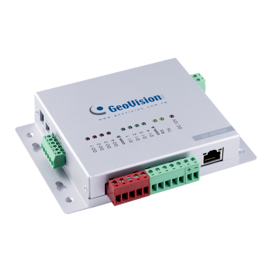
Page 6: Overview
1.4 Overview Figure 1-1 Definition Definition Definition DO 1 Lock DI 1 Door Contact Wiegand A Entry Reader DO 2 Alarm DI 2 Exit Button Wiegand B Exit Reader DO 3 LED for Access Granted DI 3 Fire Contact RS-485 +/- RS-485 Readers DO 4 LED for Access Denied... -
Page 7: Chapter 2 Installing On A Network
Installing on a Network Chapter 2 Installing on a Network Through network connection, you can access the Web interface of the controller and connect it to GV-ASManager for more comprehensive management. There are three ways to set up the controller on network. By default, when the controller is connected to a network with a DHCP server, a dynamic IP address will be assigned to the controller. -
Page 8: Checking The Dynamic Ip Address
2.1 Checking the Dynamic IP Address Follow the steps below to look up the IP address and access the Web interface of the controller. 1. Download and install GV-IP Device Utility from our website. Note: The PC installed with GV-IP Device Utility must be under the same LAN as the controller you wish to configure. -
Page 9: Configuring The Static Ip Address
IP. DDNS assigns a domain name to the controller, so GV- ASManager can always access the controller by using a static domain name. The controller supports two DDNS services: GeoVision DDNS Server and Dynamic Network Services Inc. (DynDNS). - Page 10 2. The DDNS service is provided purely as a favor to you. We hope it simplifies the process of trying to connect an IP video device to the network. GeoVision does not and cannot warrant that the DDNS service will be uninterrupted or error free. Please read Terms of Service carefully before using the service.
- Page 11 Installing on a Network Figure 2-4 Figure 2-5 2. Type a Hostname and Password based on the requirements noted on the page. 3. Type the characters or numbers shown for word verification, and click Send. 4. When the registration is complete, this page will appear. The Hostname is the domain name, consisting of the registered username and “gvdip.com”, e.g.
- Page 12 3. Select Enable DDNS. 4. Type Host Name, User Name and Password that are registered on the DDNS Server. If GeoVision DDNS is used, the system will automatically bring up the Host Name. Figure 2-7 5. Click Submit. When the setting is complete, the Status field will indicate: Register...
-
Page 13: Chapter 3 The Web Interface
The Web Interface Chapter 3 The Web Interface After installing the controller on the network, you can configure the controller’s settings on the Web interface. The left menu of the Web interface is divided into three sections: Basic Setting, Advanced Setting and Extended Device. Figure 3-1... -
Page 14: Basic Settings
3.1 Basic Settings The Basic Settings section covers general system settings, firmware update and user account settings. For details on Network Configuration, refer to Chapter 2 Installing on a Network. 3.1.1 System Setup In the left menu, click Other Configuration. This page appears. Figure 3-2... - Page 15 The Web Interface 3DES Code 1-3: Stands for Triple DES (Data Encryption Standard). Type up to three different keys for data encryption. The default 3DES Code1 is 12345678. Device Port: Keeps the default value 4000. Or modify it to match that of GV-ASManager. ...
-
Page 16: Firmware Update
3.1.2 Firmware Update Follow the steps below to update the firmware of the controller. 1. In the left menu, click Firmware Update. This page appears. Figure 3-3 2. Click Browse and select the firmware file. 3. Click Upload. This update process may take 60 seconds to complete. 4. -
Page 17: Security Configuration
The Web Interface 3.1.3 Security Configuration Follow the steps below to change the login ID and password. 1. In the left menu, click Security Configuration. 2. Modify the login name and password. The password is case sensitive and is limited to alphabets and numbers. -
Page 18: Function Configuration
3.2.1 Function Configuration In the left menu, click Function Configuration. This page appears. Figure 3-6... - Page 19 The Web Interface [ID] Enter the ID number for the controller. This ID is used by GV-ASManager to differentiate among multiple units of controllers. ID number can only be between 1 and 1000. [Door/Gate A] Select the function type and authentication mode for the use of the door/gate. Function: Define the function of the controller connected to the door/gate which is used ...
- Page 20 You can assign a camera to capture snapshots upon card presented. The captured snapshots will be saved to the built-in flash drive of GV-AS1620 and then transferred to the Access Log on GV-ASManager whenever GV-ASManager resumes connection after it has been disconnected.
-
Page 21: Parameter Configuration
3.2.2 Parameter Configuration In the left menu, click Parameter Configuration. This page appears. IMPORTANT: Once connected to GV-AS1620, GV-ASManager will load its parameters to the controller. That means some of the Parameter Settings you have configured here may be overwritten by GV-ASManager later. - Page 22 Locks or unlocks the door when a fire condition occurs. Otherwise, Fire Action remains the door’s current state by selecting Unchanged. Alarm Continuous Sets the time (1 to 10 sec.) that the alarm will continuously go off Time before it ends. Relay On Time Sets the time (1 to 600 sec.) that a gate remains open after which the gate will automatically be closed.
-
Page 23: Time Configuration
The Web Interface 3.2.3 Time Configuration In the left menu, click Time Configuration to set up system time, local time and daylight saving time period. Figure 3-8 [System Local Time] Displays the current data, time and time zone of the controller. [Local Time] Disable: Disable the manual configuration of time and date. -
Page 24: Input Configuration
3.2.4 Input Configuration In the left menu, click Input Configuration to define the input devices connected to the controller. You set the input status to either NO (normally open) or NC (normally close). Figure 3-9 3.2.5 Output Configuration In the left menu, click Output Configuration to define the output devices connected to the controller. -
Page 25: Log Viewer
The Web Interface 3.2.6 Log Viewer In the left menu, click Card Log Viewer to search for the log data. The log entries are only created when the controller is disconnected from GV-ASManager. Only up to 100 log entries of Event Log / Access Log on the Web interface can be retrieved at a time. Figure 3-11 3.2.7 System Log Viewer In the left menu, click System Log Viewer to view the current system status and dump data... -
Page 26: Extended Device
3.3 Extended Device In the left menu, click Extended Reader Configuration to define the readers connected to the controller through RS-485 or network connection. Figure 3-12 [GV-Reader / CR420 / GF1921 / 1922 / CR1320 / FR2020 Function] Define the readers connected to the controller, and then use the Function drop-down list to select the door associated with the reader. -
Page 27: Chapter 4 Troubleshooting
Troubleshooting Chapter 4 Troubleshooting Q1: GV-ASManager cannot connect to the controller over the Internet. There are several causes for this problem such as IP address conflict, incorrect connection settings and network failure. Follow the steps below to assign a fixed IP to the GV- ASManager and the controller respectively. - Page 28 5. In the IP address fields, give the controller an IP address that is NOT used by another device under the LAN, e.g. 192.168.X.XXX. Figure 4-2 6. On the GV-ASManager, type the following settings: Controller ID: 1 Network: TCP/IP IP: 192.168.X.XXX Port: 4000 User: admin Password: admin...
- Page 29 Troubleshooting Q2: The connection established between the GV-ASManager and the controller is interrupted. This may be due to IP address conflict. Follow these steps to troubleshoot the problem: 1. Disconnect the hub or switch, which connects to both the GV-ASManager and the controller, from the network.
- Page 30 Q3: GV-ASManager cannot receive card messages but the reader accepts the card when the connection between the GV-ASManager and GV-AS1620 is well established. It may be due to memory failure in the controller. Reset the controller module to factory settings. For details, see 3.1.1 System Setup.
Need help?
Do you have a question about the GV-AS1620 and is the answer not in the manual?
Questions and answers