Table of Contents
Advertisement
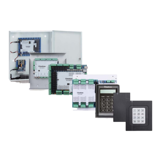
Quick Start Guide
GV-AS / EV Controller
Thank you for purchasing GV-AS / EV Controller. This guide is designed to assist the new user in
getting immediate results from the controllers. For advanced information on how to use the GV-
AS100 / 1010 / 110 / 1110 / 120 / 210 / 2110 / 2120 / 410 / 4110 / 810 / 8110 and GV-EV48, please
refer to GV-AS / EV Controller User's Manual on Software CD / DVD.
ASEV-QG-E
Advertisement
Table of Contents

Related Manuals for GeoVision GV-AS1010


Summary of Contents for GeoVision GV-AS1010
- Page 1 Quick Start Guide GV-AS / EV Controller Thank you for purchasing GV-AS / EV Controller. This guide is designed to assist the new user in getting immediate results from the controllers. For advanced information on how to use the GV- AS100 / 1010 / 110 / 1110 / 120 / 210 / 2110 / 2120 / 410 / 4110 / 810 / 8110 and GV-EV48, please refer to GV-AS / EV Controller User's Manual on Software CD / DVD.
- Page 2 GeoVision. Every effort has been made to ensure that the information in this manual is accurate. GeoVision, Inc. makes no expressed or implied warranty of any kind and assumes no responsibility for errors or omissions. No liability is assumed for incidental or consequential damages arising from the use of the information or products contained herein.
-
Page 3: Table Of Contents
Contents Contents...........................i Important Note for Maintaining Power Supply..............ii GV-AS Controller Quick Start Guide................1 1. Basic Setup for GV-AS100 / 1010 / 110 / 1110 / 120..........1 1.1 GV-AS100 / 1010 ..................... 2 1.2 GV-AS110 / 1110 ..................... -
Page 4: Important Note For Maintaining Power Supply
Important Note for Maintaining Power Supply To make sure GV-AS / EV Controllers can function properly during a power outage, be sure to replace the internal battery on the controllers when needed. It is also recommended to install a backup battery for compatible GV-AS Controllers. Refer to the following sections in GV-AS Controller User Manual for instructions on how to install a backup battery: GV-AS100 / 110 / 120 through GV-ASBox: See 9.1.4.F Connecting Backup Battery. - Page 5 Built-in Battery (GV-AS1010 / 110 / 1110 / 120 / 210 / 410 / 810 & GV-EV48) When the controller runs out of battery, the local time on the controller will be reverted back to 1999/12/31. The controller time can be found on the Web interface of the controller on the Time Setting page and in the Access Monitor / Alarm Monitor / Event Monitor of GV- ASManager.
-
Page 6: Gv-As Controller Quick Start Guide
GV-AS Controller Quick Start Guide This guide lists the basic steps required to set up a GV-AS Controller. For detailed instructions, refer to the section number listed below each step. 1. Basic Setup for GV-AS100 / 1010 / 110 / 1110 / 120 This section covers the basic settings required to start running GV-AS100 / 1010 / 110 / 1110 / 120. -
Page 7: Gv-As100 / 1010
Connect to Power Connect AS100 / 1010 to power using the supplied adaptor. 1.2.5 Connecting the Power GV-AS1010 Programming the GV-AS100 / 1010 Create a Master Card (AS100) or Enroll / Delete Card (AS1010) to add and delete cards. For other settings, use the built-in keypad to type the commands. -
Page 8: Gv-As110 / 1110
1.2 GV-AS110 / 1110 Connect card readers (Optional) Connect AS110 / 1110 to a reader.. 2.2.1 Connecting Card Readers Connect input devices Connect AS110 / 1110 to input devices (Ex: a push button to exit). 2.2.2 Connecting Input Devices GV-AS110 / 1110 Connect output devices Connect AS110 / 1110 to output devices (Ex: a door lock). -
Page 9: Gv-As120
1.3 GV-AS120 Connect card readers (Optional) Connect AS120 to a reader through Wiegand interface. 3.2.1 Connecting a Wiegand Reader Connect input devices Connect AS120 to input devices (Ex: a push button to exit). 3.2.2 Connecting Input Devices Connect output devices GV-AS120 Connect AS120 to output devices (Ex: a door lock). -
Page 10: Physical Wiring For Gv-As210 / 2110 / 2120 / 410 / 4110 / 810 / 8110 And Gv-Ev48
2. Physical Wiring for GV-AS210 / 2110 / 2120 / 410 / 4110 / 810 / 8110 and GV-EV48 2.1 GV-AS210 / 2110 / 2120 Wiegand Connect card readers 4.2.1.A Wiegand Readers Connect AS210 / 2110 / 2120 to readers through RS485 Wiegand or RS-485 interface. -
Page 11: Gv-As410 / 4110 / 810 / 8110
2.2 GV-AS410 / 4110 / 810 / 8110 Wiegand Connect card readers 5.2.1.A Wiegand Readers Connect AS410 / 4110 / 810 / 8110 to readers RS485 through Wiegand or RS-485 interface. 5.2.1.B RS-485 Readers Connect input devices Connect AS410 / 4110 / 810 / 8110 to input devices (Ex: a push button to exit). -
Page 12: Gv-Ev48
2.3 GV-EV48 Connect card readers Connect EV48 to readers through RS-485 interface. 6.2.1 Connecting RS-485 Card Readers Connect output relay Connect EV48 output relays to the corresponding floor on the elevator control panel. 6.2.2 Connecting Output Relay GV-EV48 Connect Backup Battery (Optional) Connect EV48 to backup battery in case the main power supply fails. -
Page 13: Accessing The Web Interface Of The Gv-As Controllers
After connecting the required wires and cables for the following GV-AS Controllers, access the Web interface of the GV-AS Controller to define the devices connected: GV-AS1010 / 1110 / 210 / 2110 / 2120 / 410 / 4110 / 810 / 8110 and GV-EV48. The section numbers listed here refers to the GV-AS Controller User Manual. -
Page 14: Setting Gv-As Controller On Gv-Asmanager
4. Setting GV-AS Controller on GV-ASManager After setting up the Web interface, connect the GV-AS Controller to a GV-ASManager. Through GV-ASManager, you can set up the doors and enroll cards. The section numbers listed here refers to the GV-ASManager User Manual. Install GV-ASManager Install GV-ASManager from the supplied software DVD. -
Page 15: Optional Devices For Gv-As100 / 110 / 120
5. Optional Devices for GV-AS100 / 110 / 120 To access GV-AS100 / 110 / 120 on a network, an optional device GV-ASBox or GV-ASNet is required. GV-ASBox also supports connection with additional input devices, output devices and readers through Wiegand interface and RS-485 interface. GV-ASNet supports additional readers through RS-485 connection. -
Page 16: Physical Wiring Of Gv-Asbox And Gv-Asnet
5.1 Physical Wiring of GV-ASBox and GV-ASNet The section numbers listed here refers to the GV-AS Controller User Manual. Physical Wiring of GV-ASBox Physical Wiring of GV-ASNet Connect GV-AS100 / 110 / 120 Connect GV-AS100 / 110 / 120 Connect GV-ASBox with GV-AS100 / 110 / 120. Connect GV-ASNet with GV-AS100 / 110 / 120. -
Page 17: Accessing The Web Interface Of Gv-As100 / 110 / 120
5.2 Accessing the Web Interface of GV-AS100 / 110 / 120 The section numbers listed here refers to the GV-AS Controller User Manual. Set network configurations Assign a static IP address or set up DDNS to map a dynamic IP address to a static domain name.
Need help?
Do you have a question about the GV-AS1010 and is the answer not in the manual?
Questions and answers