Table of Contents
Advertisement
Quick Links
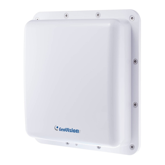
GV-AS1520 Controller
Quick Start Guide
Thank you for purchasing GV-AS1520 Controller. This guide is designed to assist the new user
in getting immediate results from the controllers. For advanced information on how to use
GV-AS1520, please refer to GV-AS1520 Controller User's Manual.
AS1520V206-QG-A
Advertisement
Table of Contents

Related Manuals for GeoVision GV-AS1520


Summary of Contents for GeoVision GV-AS1520
- Page 1 GV-AS1520 Controller Quick Start Guide Thank you for purchasing GV-AS1520 Controller. This guide is designed to assist the new user in getting immediate results from the controllers. For advanced information on how to use GV-AS1520, please refer to GV-AS1520 Controller User's Manual.
- Page 2 Under the copyright laws, this manual may not be copied, in whole or in part, without the written consent of GeoVision. Every effort has been made to ensure that the information in this manual is accurate. GeoVision, Inc. makes no expressed or implied warranty of any kind and assumes no responsibility for errors or omissions.
-
Page 3: Table Of Contents
1.3 LED Status and Beeper ......................2 2. Wiring ..........................3 3. Installation........................6 3.1 Installing GV-AS1520 ......................6 3.2 Installation Considerations ......................7 4. Installing on a Network....................12 4.1 Checking the Dynamic IP address ..................13 ... -
Page 4: Introduction
1. Introduction Welcome to the GV-AS1520 Quick Start Guide. In the following sections, you will learn the installation basics for setting up a GV-AS1520. For the detailed instructions of use, see GV-AS1520 Controller User's Manual. The latest firmware together with all required software and documentation of GV-AS1520 can found from GeoVision website. -
Page 5: Led Status And Beeper
1.3 LED Status and Beeper You can find the LED at the bottom of your GV-AS1520. Condition Beeper Boot completed Green Two long beeps Ready Green The e-tag is detected but Displays red LED Three short beeps the access is denied. -
Page 6: Wiring
Use either a Power over Ethernet (POE) adapter or a power adapter to provide power to the GV-AS1520. IMPORTANT: GV-AS1520 can only accept PoE power supply or the DC power adapter as one power source. Connecting two power sources at the same time will cause damage to the unit. - Page 8 Each relay output (DO_NO1 ~ 4) can only support a maximum power consumption of 30V DC, 500mA. Connecting the PC Use TCP/IP to connect GV-AS1520 to a computer that allows you to access its Web interface and GV-ASManager if the computer is installed with GV-ASManager. Connecting the Power When using a Power Adapter connect the 12V DC and GND wires to a 12V DC power adapter and then connect the power adapter to a power source.
-
Page 9: Installation
3. Installation 3.1 Installing GV-AS1520 You can install the reader on a pole or a pillar. Two types of pole mounts are recommended, as indicated below. Note: Make sure the diameter of the pole is within 53 mm (0.17 ft). -
Page 10: Installation Considerations
Installation 3. Adjust the angle of the U-clip on L-bracket and secure the hexagon screw nuts. 4. Here is an overview of the pole mount. 3.2 Installation Considerations The reading range of 10 m (33 ft) is achieved when the RFID Reader and the RFID tag are installed at the same height, facing each other. - Page 11 When facing opposite directions, RFID Readers must be placed 20 cm (7.9 in) apart or more. When facing the same direction, RFID Readers must be assigned to separate bands (available upon request when purchasing). To further improve the reading range of your RFID installations, follow the steps below. 1.
- Page 12 Installation The recommended maximum height to set RFID Reader is 1.8 - 2.2 m (5.9 - 7.2 ft). The height should not be lower than that of the RFID Tag being recognized. The recommended angle to set RFID Reader is 15-20 degree. Adjust the angle according to the actual installation site.
- Page 13 5. Recommended Tag Position Vehicles Place the Tag on the front windshield or headlight, at the nearest reading range to the reader. When placing the Tag on the headlight, keep the Tag away from the metal body of the vehicle. If the car windshield glass contains metallic line, it will affect the reading range.
- Page 14 Installation 7. Notice When the installation is complete, examine and adjust the environment parameters again for better reading results. When two or more RFID Readers are installed together, co-channel interference might occur. Note: To avoid channel interference, see the requirements for RFID Readers facing opposite directions or the same direction on page 12.
-
Page 15: Installing On A Network
4. Installing on a Network You can install GV-AS1520 on a network and set up general settings and input device through its Web interface. Through the network connection, you can also connect GV-AS1520 to GV-ASManager for more comprehensive management. There are three ways to set up GV-AS1520 on the network. -
Page 16: Checking The Dynamic Ip Address
4.1 Checking the Dynamic IP address Download and install GV-IP Device Utility program from our website. Note: The PC installed with GV-IP Device Utility must be under the same LAN as GV-AS1520. On the GV-IP Utility window, click the button to search for the IP devices connected in the same LAN. -
Page 17: Configuring The Static Ip Address
In the DHCP Client section, click Disable. Type the static IP address information, including IP Address, Subnet Mask, Default Gateway and Domain Name Server. Click Submit. When the setting is complete, the Status field will indicate Register Success. Then GV-AS1520 can be accessed with this fixed IP address. -
Page 18: Configuring Ddns Connection
DDNS servers to map a dynamic IP address to a static domain name or device. For LAN connection, GV-localDDNS Server is provided. For Internet connection, two DDNS servers are supported: GeoVision DDNS Server and Dynamic Network Services Inc. (DynDNS).
Need help?
Do you have a question about the GV-AS1520 and is the answer not in the manual?
Questions and answers