Table of Contents
Advertisement
Quick Links
Advertisement
Table of Contents

Related Manuals for Kipp & Zonen CM 4


Summary of Contents for Kipp & Zonen CM 4
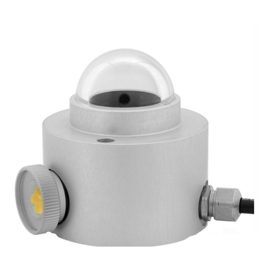
- Page 1 CM 4 High Temperature Pyranometer Instruction Manual...
-
Page 2: Important User Information
IMPORTANT USER INFORMATION Reading this entire manual is recommended for full understanding of the use of this product. The exclamation mark within an equilateral triangle is intended to alert the user to the presence of important operating and maintenance instructions in the literature accompanying the instrument. - Page 3 © COPYRIGHT 2010 KIPP & ZONEN All rights reserved. No part of this publication may be reproduced, stored in a retrieval system or transmitted in any form or by any means, without permission in written form from the company. Manual version 1007...
-
Page 4: Calibration Certificate
CALIBRATION CERTIFICATE The calibration certificate supplied with the instrument is valid from the date of first use. Even though the calibration certificate is dated relative to manufacture the instrument does not undergo any sensitivity changes when kept in the original packing. From the moment the instrument is taken from it’s packaging and exposed to irradiance the sensitivity will deviate with time. -
Page 5: Declaration Of Conformity
Kipp & Zonen B.V. Delftechpark 36 2628 XH Delft The Netherlands Declare under our sole responsibility that the product Type: CM 4 Name: High Temperature Pyranometer To which this declaration relates is in conformity with the following standards Imissions EN 50082-1... -
Page 8: Table Of Contents
TABLE OF CONTENTS IMPORTANT USER INFORMATION ..........1 CALIBRATION CERTIFICATE ............2 DECLARATION OF CONFORMITY ..........4 1 GENERAL INFORMATION............9 ..............9 NTRODUCTION ....10 HYSICAL PRINCIPLES OF THE PYRANOMETER 1.2.1 Temperature Dependency ...........11 1.2.2 Spectral properties of the glass dome ......13 1.2.3 Directional / Cosine response........14 1.2.4 Non-linearity..............15 2 LIST OF SPECIFICATIONS.............17... - Page 9 6.3.5 Traceability to World Radiometric Reference ....35 7 FREQUENTLY ASKED QUESTIONS (FAQ’S).......37 8 TROUBLE SHOOTING ............39 9 PART NUMBERS / SPARE PARTS / OPTIONS.....41 APPENDIX I PYRANOMETER CLASSIFICATION ACCORDING TO WMO GUIDE 1996 ....43 APPENDIX II PT-100 SPECIFICATIONS ......45 APPENDIX III LIST OF WORLD AND REGIONAL RADIATION CENTRES........47 APPENDIX IV...
-
Page 10: General Information
1. GENERAL INFORMATION GENERAL INFORMATION INTRODUCTION The CM 4 High Temperature Pyranometer is an instrument for measuring solar or artificial light irradiance. The instrument is specially designed for usage under extreme irradiance and temperature conditions. With an operating temperature range of -40°C to +150°C and measurement up to 4000 W/m²... -
Page 11: Physical Principles Of The Pyranometer
The CM 4 Pyranometer complies with specifications according to the ISO 9060 standard, as defined in the ‘Guide to meteorological Instruments and Methods of Observation’, sixth edition, 1996, of the World Meteorological Organisation (WMO*) – Geneva – Switzerland. * The WMO classification is adapted from the international standard ISO 9060 (1990). -
Page 12: Temperature Dependency
ISO 9060 defines this temperature response as the percentage deviation due to a change in the ambient temperature within a specific range of 50 K. The CM 4 temperature dependency however is specified within an range of 170 K. To keep the pyranometer performance acceptable the instrument output signal is electrically compensated. - Page 13 Instrument temperature (°C) Figure 1.2: Typical temperature dependency curve of the CM 4. The CM 4 High Temperature Pyranometer is supplied with its own individual graph of temperature dependence of sensitivity. Monitoring the temperature during operation will allow easy data correction afterwards for improved measurement accuracy.
-
Page 14: Spectral Properties Of The Glass Dome
1. GENERAL INFORMATION 1.2.2 Spectral properties of the glass dome The spectral properties of a pyranometer are determined by the properties of the black absorbent paint and the glass dome. The spectral response is given in figure 1.3. Figure 1.3: The spectral transmission of the glass dome pyranometer combined with the spectrum of the sun under a clear sky. -
Page 15: Directional / Cosine Response
Figure 1.4 shows the typical curve and the maximum percentage deviation of a CM 4 pyranometer. The vertical axis shows the deviation from ideal behaviour, expressed in percents of the ideal value. -
Page 16: Non-Linearity
Even when the pyranometer is exposed to a very intense artificial radiating source the non-linearity of the sensor sensitivity is small. The CM 4 non- linearity is show in figure 1.5. - Page 17 1.01 1.00 0.99 0.98 0.97 0.96 1000 1500 2000 2500 Irradiance [W/m²] Figure 1.5: CM 4 non-linearity, sensitivity variation as a function of the irradiance, with 500 W/m² as reference level during calibration.
-
Page 18: List Of Specifications
SPECIFICATIONS LIST OF SPECIFICATIONS Spectral range: 300 to 2800 nm, 50% points Sensitivity: 7 µV/Wm (nominal) 500 to 2000 Ω Impedance: Response time: 18 s (95% response) < 8 s (63% response) Non-linearity: Max. 3 % (0 - 2500 W/m Directional error (at 80°... - Page 19 Temperature sensor: Pt-100 Construction: Receiver paint: Carbon Black Dome: Glass Desiccant: Silica gel Materials: Anodised aluminium case Stainless steel screws etc Viton O-rings Drying cartridge aluminium and glass lid Cable material: 6-wire shielded cable Pt-100 specifications: Type Heraeus M-GX 1013, DIN IEC 751.
- Page 20 SPECIFICATIONS Figure 2.1: CM 4 Dimensions.
-
Page 22: Installation
The CM 4 pyranometer delivery will include the following items: CM 4 pyranometer Calibration certificate... -
Page 23: Outdoor Installation
3.2.1 Outdoor installation When installed permanently, the pyranometer can be attached to its mounting platform by means of the holes that are drilled through the body, see figure 2.1. Preferred orientation is with the cable pointing to the nearest pole. When installed on a mast, preferred orientation is such that no shadow is cast on the pyranometer during any time of the day. -
Page 24: Electrical Connection
3. INSTALLATION ELECTRICAL CONNECTION The CM 4 is provided with a special 10 m cable with six leads and a shield covered with a black sleeve. The colour code is: plus blue minus Shield case Pt-100 temperature sensor (4 – wire connection) - Page 25 Circuit diagram of the CM 4 Pyranometer and connection to readout equipment. It is evident that application of attenuator circuits to the CM 4 output in order to modify the calibration factor is not recommended because the temperature response will also be affected. However, recorders...
- Page 26 3. INSTALLATION For amplification of the pyranometer signal Kipp & Zonen recommends the 4-20 mA Signal Amplifier, available from Kipp & Zonen. This amplifier converts the micro-Volt output from the pyranometer into a standard 4–20 mA signal. Zero and Span adjustment of the pyranometer signal are provided.
-
Page 28: Operation
1, or by multiplication of the voltage value with the reciprocal of the sensitivity, often called the calibration factor. The CM 4 pyranometer sensitivity is given in the supplied calibration certificate. For calculation of the solar irradiance the following formula must be... -
Page 30: Maintenance
5. MAINTENANCE MAINTENANCE Once installed the pyranometer needs little maintenance. The pyranometer dome must be kept clean and inspected regularly. Ensure that the silica gel is still coloured orange. When the orange silica gel in the drying cartridge is turned completely transparent (normally after several months), it must be replaced by active silicagel as supplied in the small refill packs. -
Page 32: Calibration
6. CALIBRATION CALIBRATION INITIAL CALIBRATION The ideal pyranometer should always have a constant ratio of voltage output to irradiance level (outside the instrument in the plane of the sensing element). This ratio is called sensitivity (S ) or ensitivity responsivity. The calibration (sensitivity) factor of a particular pyranometer is unique. - Page 33 Accurate calibrations can also be done outdoors under clear conditions by comparison to a reference pyrheliometer. Many National Weather Services have calibration facilities. Their standard pyrheliometer is compared with the World Radiometric Reference (maintained at Davos, Switzerland) embodied by several absolute pyrheliometers (black body cavity type).
-
Page 34: Calibration Procedure At Kipp & Zonen
6. CALIBRATION CALIBRATION PROCEDURE AT KIPP & ZONEN 6.3.1 The facility The calibration facility at Kipp & Zonen consists of a good quality film sun (Osram) fed by an AC voltage stabiliser. This is used as an artificial sun. It embodies a 150 W Metal Halide lamp with compact filament. -
Page 35: Calculation
the lamp optics etc. Therefore the pyranometers are interchanged and the whole procedure is repeated. We get another pair of values: A' and B'. 6.3.3 Calculation The sensitivity of the unknown pyranometer is calculated using formula 2: ⋅ (Formula 2) = Sensitivity of the reference pyranometer at 20 °C. -
Page 36: Traceability To World Radiometric Reference
6. CALIBRATION 6.3.5 Traceability to World Radiometric Reference Working reference pyranometers are maintained at Kipp & Zonen. Each reference pyranometer is characterised. Linearity, temperature dependence curve and directional response are well known. The working reference pyranometers are calibrated each year at the World Radiation Center in Davos, Switzerland, according to the component method. -
Page 38: Frequently Asked Questions (Faq's)
When care is not taken one can easily make the desiccant cartridge the primary entry point. See chapter 5 for the maintenance of the CM 4 Pyranometer. Note: Water vapour transport through the cable is also possible when the open end of the cable at the readout device is in a humid... -
Page 40: Trouble Shooting
8 TROUBLE SHOOTING TROUBLE SHOOTING The following contains a procedure for checking the instrument in case it appears that it does not function as one could expect. Trouble shooting: Output signal fails or shows improbable results: Check the wires, whether they are properly connected to the readout equipment. -
Page 42: Part Numbers / Spare Parts / Options
9 PART NUMBERS / SPARE PARTS / OPTIONS PART NUMBERS / SPARE PARTS / OPTIONS Description Part no. Drying Cartridge kit 0356 111 (incl. Cartridge, Cover, Rubber Ring) Silica gel refill pack 2643 951... -
Page 44: Appendix Ipyranometer Classification According To Wmo Guide 1996
APPENDIX I PYRANOMETER CLASSIFICATION ACCORDING TO WMO GUIDE 1996 High Good Moderate Characteristics quality quality quality Secondary ISO 9060 classification First class Second class standard Response time (95 percent response) < 15 s < 30 s < 60 s Zero offset: ±... - Page 45 Achievable uncertainty, 95 percent confidence level Hourly totals Daily totals...
-
Page 46: Appendix Ii Pt-100 Specifications
APPENDIX II PT-100 SPECIFICATIONS Temp. Resistance Temp. Resistance Temp. Resistance [°C] [Ω] [°C] [Ω] [°C] [Ω] 84,27 96,87 109,35 84,67 97,26 109,73 85,06 97,65 110,12 85,46 98,04 110,51 85,85 98,44 110,90 86,25 98,83 111,29 86,64 99,22 111,67 87,04 99,61 112,06 87,43 100,00 112,45... - Page 47 Resistance Resistance Resistance Temp. Temp. Temp. [Ω] [°C] [°C] [°C] [Ω] [Ω] 121,71 133,95 146,07 122,09 134,33 146,44 146,82 122,47 134,71 122,86 135,09 147,20 123,24 135,47 147,58 147,95 123,63 135,85 124,01 136,23 148,33 136,61 148,70 124,39 124,78 136,99 149,08 125,16 137,37 149,46 137,75...
-
Page 48: Appendix Iii List Of World And Regional Radiation Centres
APPENDIX III LIST OF WORLD AND REGIONAL RADIATION CENTRES World Radiation Centres Davos (Switzerland) St. Petersburg (Russia) Regional Radiation Centres Region I Africa: Cairo (Egypt) Khartoum (Sudan) Kinshasa (Zaire) Lagos (Nigeria) Tamanrasset (Algeria) Tunis (Tunisia) Region II Asia: Poona (India) Tokyo (Japan) Region III South America:... -
Page 50: Appendix Iv Recalibration Service
APPENDIX IV RECALIBRATION SERVICE Pyranometers, UV-meters, Pyrgeometers & Sunshine duration sensors Kipp & Zonen solar radiation measurement instruments comply with the most demanding international standards. In order to maintain the specified performance of these instruments, Kipp & Zonen recommends calibration of their instruments at least every two years. This can be done at the Kipp &... - Page 52 RECALIBRATION FORM Name Company/Institute Address Postcode + City Country Phone E-mail I would like to receive a price estimate for recalibration I would like to submit my instruments for recalibration Type/Model: Qty: Requested delivery time I intend to send the instrument(s) to Kipp &...
- Page 53 Our customer support remains at your disposal for any maintenance or repair, calibration, supplies and spares. Für Servicearbeiten und Kalibrierung, Verbrauchsmaterial und Ersatzteile steht Ihnen unsere Customer Support Abteilung zur Verfügung. Notre service 'Support Clientèle' reste à votre entière disposition pour tout problème de maintenance, réparation ou d'étalonnage ainsi que pour les accessoires et pièces de rechange.
Need help?
Do you have a question about the CM 4 and is the answer not in the manual?
Questions and answers