Table of Contents
Advertisement
Quick Links
Advertisement
Table of Contents

Related Manuals for Digitus DN-95359


Summary of Contents for Digitus DN-95359
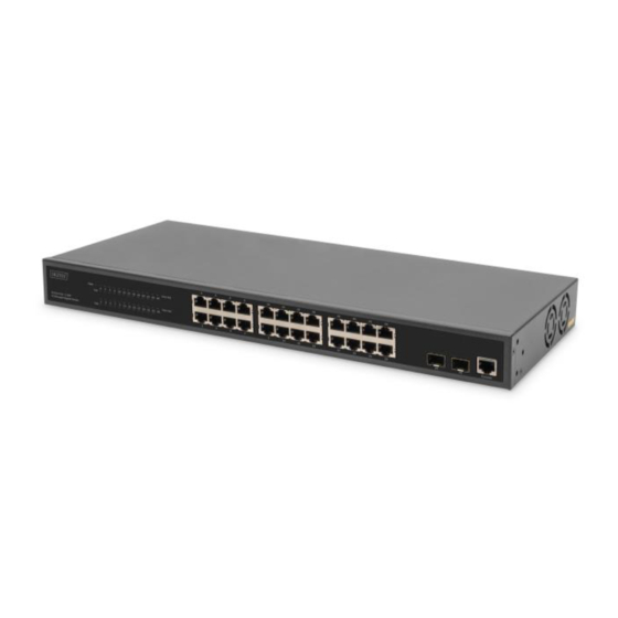
- Page 1 24 Port L2 Managed Gigabit Ethernet PoE Switch Quick Installation Guide DN-95359...
- Page 2 1. Introduction The DN-95359 is a manageable 24 +2 port PoE switch with L2 features. It is mainly used in the structural LAN area. With a total PoE power budget of 430 watts, the DN-95359 supplies up to 24 connected PoE devices such as IP security cameras or VoIP telephones with up to 30 watts per port.
-
Page 3: Package Contents
3. Package Contents 1 x DN-95359 24 Port PoE Switch 1 x User Manual 1 x Power Cord 1 x DB9 to RJ45 Cable 1 x Rack Mount Kit 4 x Rubber Feet 4. Specification... - Page 4 Operating Temperature 0 to 40℃ Storage Temperature -10 to 70℃ Operating Humidity 5 to 95% Noncondensing Power Method 100-240VAC, 50/60Hz Max. Power Including PoE Output: 450W Consumption Excluding PoE Output: 20W Power over Ethernet PoE Interfaces Ports 1-24 PoE Standard IEEE802.3af, IEEE802.3at Max.
- Page 5 Source IP / Destination IP / Source Destination IP Each port can be configured into Port Protection isolated protected port from each other MAC Configuration MAC Address Table Support Management Transfer Mode Support IVL transfer mode Static MAC Address Support MAC Binding Support MAC Address Filter...
- Page 6 LLDP Protocol Support LLDP and LLDP-MED Totally compatible with UDLD protocol UDLD Protocol of CISCO Host Routing Static ARP Support Static Routing Support Multicast Static Multicast MAC Support Address IGMP SNOOPING Support Support GMRP Support Access Control List (ACL) Based on Standard IP Support Based on Extend IP Support...
- Page 7 Support limit of data flow Support statistics of data flow Support mirroring of data flow Security Support start and end TELNET, WEB and SNMP serve Support TELNET, WEB and SNMP serve Administrative Security binding with Standard IP ACL Support control the number of user for TELNET Switch self-security protect, forbid CPU Protect...
- Page 8 port, when the DHCP get IP address , to prevent ARP spoofing IPv6 ICMPv6 Support IPv6 Neighbor Discovery Support MLD Snooping Support IPv6 Telnet Support Management Feature Support serial port management CLI Management Support TELNET management Support SSH management WEB Management Support Support SNMP protocol SNMP Management...
-
Page 9: Front Panel
Support 802.3ah Support 802.1ag DHCP Client Support Configuration Download Support / Upload Upgrade Firmware Support Support local timer management Timer Management Support SNTP protocol get clock Debugging Tools PING Support TRACEROUTE Support TELNET Client Support 5. Panel infomation Front panel PWR LED:The Power LED lights up when the Switch is connected to a power source. -
Page 10: Real Panel
Real panel Power input: Supports input voltages 100-240VAC, 50/60Hz. Switch: turn on the switch after inserting the power cord, “I” means to turn on, “O” means closing. Grounding: use specialized ground lead connect 6. Hardware installation This chapter provides unpacking and installation information for the switch. -
Page 11: Desktop Or Shelf Installation
6.2 Desktop or Shelf Installation When installing the switch on a desktop or shelf, the rubber feet included with the device must be attached on the bottom at each corner of the device's base. Allow enough ventilation space between the device and the objects around it. 6.3 Rack Installation The switch can be mounted in an EIA standard size 19-inch rack, which can be placed in a wiring closet with other equipment. -
Page 12: Power Failure
6.4 Plugging in the AC Power Cord You can connect AC power supply cord to switch back and the other side connect the power outlet. (Power outlet might as well grounding and support over voltage protection). Warning: Do not turn on the power switch before power cables are connected. -
Page 13: Getting Started
C) Mechanical Loading - Mounting of the equipment in the rack should be such that a hazardous condition is not achieved due to uneven mechanical loading. D) Circuit Overloading - Consideration should be given to the connection of the equipment to the supply circuit and the effect that overloading of the circuits might have on overcurrent protection and supply wiring. -
Page 14: Connecting To The Switch
7.3 Connecting to the Switch You will need the following equipment to begin the web configuration of your device: 1. PC with a RJ-45 Ethernet connection 2. Standard Ethernet cable Connect the Ethernet cable to any of the ports on the front panel of the switch and to the Ethernet port on the PC. - Page 15 After a successful login, the main page will appear as follows, and you can click the menu on the left side to configure the corresponding functions.
-
Page 16: Console Port Interface
8. Console Port Interface The smart switch has a monitor port (Console port). Rate 9600bps, standard RJ45 plug. Use a dedicated monitoring cable to lead the port to the PC serial port connection, as follows: The RJ45 connector used by the Console port is shown in the figure below, and the RJ45 plug corresponds to the RJ45 socket, from left to right numbered from 1 to 8. - Page 17 This cable is used to connect the console port of the switch to the external monitoring terminal. One end of the RJ45 eight-pin plug, the other end is a 25-hole plug (DB25) and 9-hole plug (DB9), RJ45 head into the switch’s console port socket, DB25 and DB9 can be used according to the requirements of the terminal serial port, the cable internal connection schematic as follows: RJ45<===>DB9...
Need help?
Do you have a question about the DN-95359 and is the answer not in the manual?
Questions and answers