Table of Contents
Advertisement
Quick Links
Advertisement
Table of Contents

Subscribe to Our Youtube Channel
Related Manuals for Digitus DN-95323-1


Summary of Contents for Digitus DN-95323-1
- Page 1 Fast Ethernet PoE af/at 8-port Switch + 2 uplinks User Manual DN-95323-1 Rev. 2...
-
Page 2: Package Contents
User Manual Power Cord Accessories (Rubber Feet*4, 19” bracket*2) If any part is lost and damaged, please contact your local agent immediately. Introduction The DIGITUS® 8-port Fast Ethernet Switch with 8 Power over Ethernet ports provides your network noticeable improvement in performance and efficiency. -
Page 3: Dip Switch
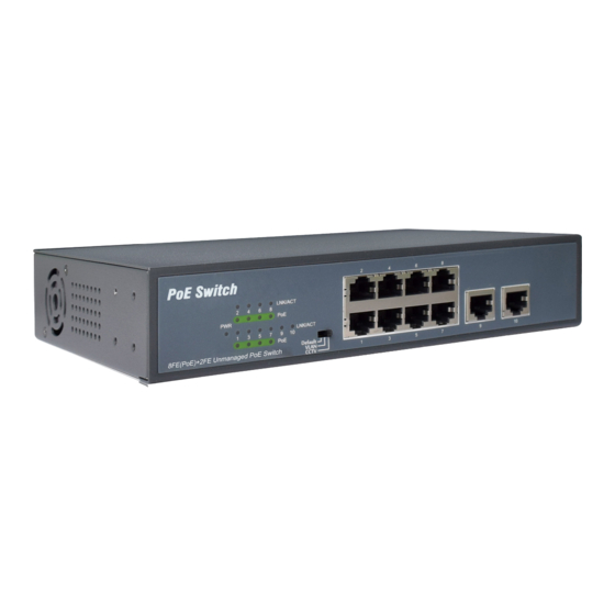
Hardware Description Front Panel The Front Panel Consists of Ethernet Ports. The LED indicators are also located on the panel. DIP Switch The DIP switch located on the left panel. Default: The factory default mode, normal communication between port 1~10. VLAN: Port 1-8 are isolated to stop broadcast Storm and increase forwarding rate of frame but can... -
Page 4: Led Indicator
LED indicator Color Function Off: No Power supply Green Light: Indicates the switch has power Off: No device is connected to the corresponding port Light: Indicates the link through that LNK/ port is successfully Established at Green 10/100Mbps Blink: Indicates that the Switch is actively sending or receiving data over that port Off: No PoE powered device (PD) -
Page 5: Power Socket
Power socket Connect the female connector of the power cord here, and the male connector to the AC (Alternating Current) power outlet. Please make sure the voltage of the power supply meets the requirement of the input voltage Grounding column The switch already comes with lightning protection mechanism. -
Page 6: Desktop Installation
Ensure proper ventilation of the equipment room and keep the ventilation vents of the switch free of obstruction Make sure that the operating voltage is the same one labeled on the switch Do not open the chassis while the switch is operating or when electrical hazards are present to avoid electrical shocks. -
Page 7: Wall-Mounted Installation
Wall-mounted installation Fix the two screws on the wall as shown in the figure below Place the switch smoothly on the screws to fix it to the wall Turn on the switch Please connect the AC power cord into the rear of the switch and to an electrical outlet (preferably one that is grounded). -
Page 8: Specifications
Specifications Model 8*FE (PoE)+2FE Uplink PoE Switch IEEE802.3, IEEE802.3u, IEEE802.3az, Standard IEEE802.3x, IEEE802.3af, IEEE802.3at 10BASE-T: UTP category 3,4,5 cable (≤100m) Network Media 100BASE-TX: UTP category 5 cable (≤100m) MAC Address Table 1K, Auto-learning, Auto-aging Transfer mode Store-and-Forward Frame Forward Rate 10Base-T: 14881pps/Port 100Base-TX: 148810pps/Port Switching Capacity... - Page 9 This is a Class A product. In home environment, this product may cause radio interference. In this case, the user may be required to take appropriate measures. Hereby Assmann Electronic GmbH, declares that the Declaration of Conformity is part of the shipping content. If the Declaration of Conformity is missing, you can request it by post under the below mentioned manufacturer address.
Need help?
Do you have a question about the DN-95323-1 and is the answer not in the manual?
Questions and answers