
Related Manuals for Digitus DN-95348-1


Summary of Contents for Digitus DN-95348-1
- Page 1 Gigabit Ethernet PoE Switch 24-port PoE + 2-port SFP, 370W PoE budget Quick Installation Guide DN-95348-1...
-
Page 2: Table Of Contents
6.4 Switch connection to the PD ..........10 1. Introduction The DIGITUS 24-Port Gigabit Rack mount Switch with 24 Power over Ethernet ports and two additional SFP Fiber Port, offers your network significant improvement in terms of performance and efficiency. Thanks to PoE support, you only need a single (network) cable for power and data transfer. -
Page 3: Features
2. Features 1. Supporting Normal mode, VLAN mode and Flow control mode, flexible to switch 2. Gigabit Ethernet Speed 3. Additional 2 port SFP-Uplink for Fiber Technology 4. Rack mountable in system rack (1U) 5. 24 x 10/100 / 1000 Mbps self-adapting RJ45 ports, support port auto-flip (Auto MDI/MDIX);... - Page 4 1000Base-T: UTP category 5e, 6 cable (maximum 100m) 1000Base-SX: 62.5μm/50μm MMF(2m~550m) 1000Base-LX: 62.5μm/50μm MMF(2m~550m) Or 10μm SMF(2m~5000m) Transfer Method Store-and-Forward MAC Address Table Switching Capacity 52Gbps Packet Forwarding Rate 38.688Mpps Packet Buffer 4.1Mbit Jumbo Frame 9216Bytes Normal Enable Flow Control and all ports can mode communicate with each other...
-
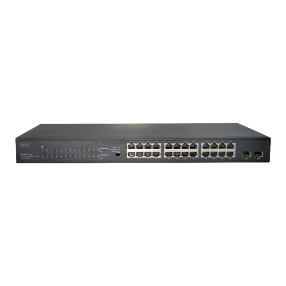
Page 5: External Component Description
Support Support MAC address self-learning Dimensions (W x D x H) 440x208x44mm Operating Temperature: 0°C ~45°C Storage Temperature: -40°C ~70°C Operating Humidity: Environment 10%~90% non-condensing Storage humidity: 5%~90% non-condensing 5. External Component Description 5.1 Front Panel The front panel of the Switch consists of a series of LED indicators, one Mode Switch, 24 x 10/100/1000Mbps RJ-45 ports and 2x SFP ports as shown as below. - Page 6 The following chart shows the LED indicators of the Switch along with explanation of each indicator Faceplate LED Indicator Status Indication Marker Power Off Power Indicator Solid green Power On The port is NOT connected The port is connected Solid green Ethernet port at 1000Mbps.
-
Page 7: Real Panel
Mode Control: You can select the switch mode. Normal mode (Normal): Enable Flow Control and all ports can communicate with each other. Flow control mode: Disable Flow Control and all ports can communicate with each other. VLAN mode: 1 to 24 cannot communicate with each other, but can ... -
Page 8: Installing And Connecting The Switch
6. Installing and Connecting the Switch This part describes how to install your PoE Ethernet Switch and make connections to it. Please read the following topics and perform the procedures in the order being presented. 6.1 Installation Please follow the following instructions in avoid of incorrect installation causing device damage and security threat. - Page 9 1. Attach the mounting brackets on the Switch's side panels (one on each side) and secure them with the screws provided. 2. Use the screws provided with the equipment rack to mount the Switch on the rack and tighten it. Power on the Switch: The Switch is powered on by the AC 100-240V 50/60Hz internal high- performance power supply.
-
Page 10: Connect Computer (Nic) To The Switch
6.3 Connect Computer (NIC) to the Switch Please insert the NIC into the computer, after installing network card driver, please connect one end of the twisted pair to RJ-45 jack of your computer, the other end will be connected to any RJ-45 port of the Switch, the distance between Switch and computer is around 100 meters.
Need help?
Do you have a question about the DN-95348-1 and is the answer not in the manual?
Questions and answers