Advertisement
Quick Links
Advertisement

Related Manuals for Digitus DN-95357


Summary of Contents for Digitus DN-95357
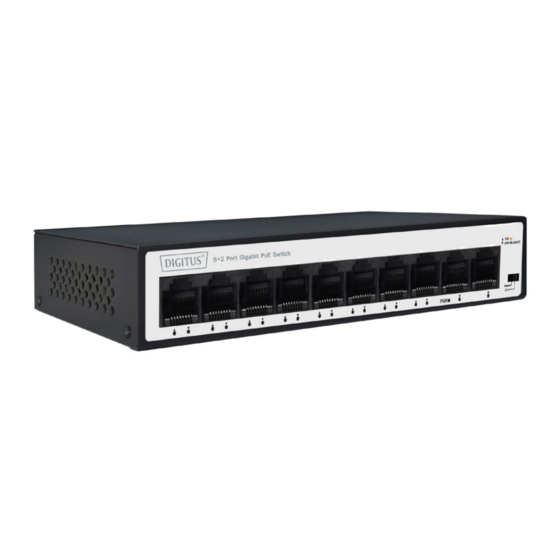
- Page 1 8+2 Port Gigabit PoE Switch Quick Installation Guide DN-95357...
-
Page 2: Table Of Contents
Table of Contents 1. Introduction ................3 2. Main Features ................. 3 3. Package Contents ..............3 4. Product Specification ............... 4 5. Hardware Description .............. 5... -
Page 3: Introduction
1. Introduction DN-95357 has a CCTV function for 250 meters of ultra-long-distance transmission. Users can choose to turn on or off the CCTV function. Improve network security and restrain network storms, facilitate management and maintenance, and meet the networking and access requirements of enterprises, communities, hotels. -
Page 4: Product Specification
4. Product Specification Technical Interface 10*10/100/1000Mbps auto-negotiation RJ45 port PoE port 1 ~ 8 PoE stand IEEE802.3af/at PoE total 60 W Power supply 65 W Key function CCTV PoE port output Max 30W RJ45 PoE power supply Mode A, Anode 1/2, Cathode 3/6 Indicator PWR (Green), LNK/ACT (Green) -
Page 5: Hardware Description
Operating Temperature 0°C ~ 40 °C Storage Temperature -40 °C ~ 70 °C Operating Humidity 10% ~ 90% non-condensing Storage Humidity 5% ~ 90% non-condensing Surge Protection Common mode ± 2KV, differential mode ± 1KV MTBF >50000 hour Electrostatic standard Contact ±6KV, air ±... - Page 6 Note: After change the mode, there is no need to restart manually to make the corresponding configuration take effect. LED indicator Color Function Off: No Power supply. Green Light: Indicates the switch has power. Off: No device is connected to the corresponding port.
- Page 7 Rear Panel The rear panel of the PoE Switch indicates an AC inlet power socket, which accepts input power from 100 to 240V AC, 50/60HZ. Power socket Connect the female connector of the power cord here, and the male connector to the AC (Alternating Current) power outlet. Please make sure the voltage of the power supply meets the requirement of the input voltage.
- Page 8 Installation the Switch This part describes how to install your Ethernet Switch and make connections to it. Please follow the following instructions in avoid of incorrect installation causing device damage and security threat. • Before cleaning the switch, unplug the power plug of the switch first.
- Page 9 Desktop Installation Install the Switch on a desktop, please attach these cushioning rubber feet provided on the bottom at each corner of the Switch in case of the external vibration. Allow adequate space for ventilation between the device and the objects around it.
- Page 10 Wall-mounted installation In the first two fixed screw on the wall as shown in the figure below. Aim at the two fixed hole switches (M4 screw, nut diameter 7mm) and the machine smoothly on the screw. Turn on the switch Please connect the AC power cord into the rear of the switch and to an electrical outlet (preferably one that is grounded).
- Page 11 Disclaimer This is a Class A product. In home environment, this product may cause radio interference. In this case, the user may be required to take appropriate measures. Hereby Assmann Electronic GmbH, declares that the Declaration of Conformity is part of the shipping content. If the Declaration of Conformity is missing, you can request it by post under the below mentioned manufacturer address.
Need help?
Do you have a question about the DN-95357 and is the answer not in the manual?
Questions and answers