
Related Manuals for Digitus DN-95355


Summary of Contents for Digitus DN-95355
- Page 1 16/24 Port Fast Ethernet PoE Switch, 1 Combo (RJ45+SFP) and 1 RJ45 Gigabit Uplinks Quick Installation Guide DN-95355 - DN-95356...
-
Page 2: Table Of Contents
6.2 Rack-mountable Installation ..........8 6.3 Turn on the switch ............. 9 1. Introduction DN-95355 PoE Switch is 16-port 10/100Mbps PoE + 1G Combo + 1GE PoE Switch. DN-95356 PoE Switch is 24-port 10/100Mbps PoE + 1G Combo + 1GE PoE Switch. -
Page 3: Features
1x User Guide 1x Power Cord Accessories (hanging ears x2, Rubber Feet x4, screw x8) 4. Specifications Model DN-95355 DN-95356 PoE Port Port 1~16 Port 1~24 IEEE802.3, IEEE802.3u, IEEE802.3ab, Standards and Protocols IEEE802.3z, IEEE802.3x, IEEE802.3af, IEEE802.3at ... - Page 4 1000BASE-T: UTP category 5e, 6 cable (≤100m), 1000BASE-X: SMF, MMF SFP module Transfer Method Store-and-Forward 10Base-T: 14881pps/Port Frame Forward Rate 100Base-TX: 148810pps/Port 1000Base-T/X: 1488095pps/Port Switching Capacity 7.2G 8.8G 1x Fan Power Input AC: 100~240V, 50/60Hz Packet Forwarding Rate 5.4Mpps 6.5Mpps...
-
Page 5: Hardware Description
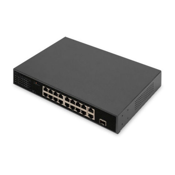
5.1 Front Panel The Front Panel Consists of 16/24-Port 10/100M Auto-Negotiation Ethernet RJ45 Ports, 1-Port Gigabit Combo Port and 1x 10/100/1000 RJ45 port. The LED indicators also on located on the panel. DN-95355 1. Status indicators 2. Switch 3. 16x 10/100Mbps 4. - Page 6 LED indicator: Color Function Off: No Power supply Green Light: Indicates the switch has power Off: No device is connected to the corresponding port. LNK/ Light: Indicates the link through that port is Green successfully. Blink: Indicates that the Switch is actively sending or receiving data over that port.
-
Page 7: Rear Panel
5.2 Rear Panel The rear panel of the PoE Switch indicates an AC inlet power socket, Grounding Column. 1. AC power socket 2. Grounding 6. Installation the Switch This part describes how to install your Ethernet Switch and make connections to it. Please follow the following instructions in avoid of incorrect installation causing device damage and security threat. -
Page 8: Desktop Installation
6.1 Desktop Installation Install the Switch on a desktop, please attach these cushioning rubber feet provided on the bottom at each corner of the Switch in case of the external vibration. Allow adequate space for ventilation between the device and the objects around it. The installation diagram is as follows: 6.2 Rack-mountable Installation The switch is rack-mountable and can be installed on an EIA-11-inch equipment rack. -
Page 9: Turn On The Switch
6.3 Turn on the switch Plug in the negative connector of the provided power cord into the power socket of the device, and the positive connector into a power outlet. After the device is powered on, it begins the Power-On Self-Test. The PWR LED indicator will light on all the time.
Need help?
Do you have a question about the DN-95355 and is the answer not in the manual?
Questions and answers