
Related Manuals for Badger Meter RCM 2000


Summary of Contents for Badger Meter RCM 2000
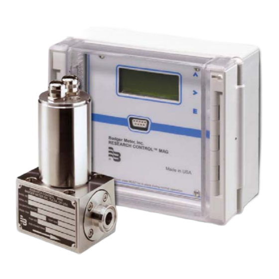
- Page 1 ® Badger Meter Europa GmbH Model RCM 2000 Research Control MAG meter Low flow magnetic flow meter INSTALLATION AND OPERATION MANUAL September 2004 Version RCM-09/04-e...
-
Page 2: Table Of Contents
Content Page 1. Basic safety advices......................1 2. Scope ..........................2 3. Unpacking & inspection....................2 4. System diagram .......................2 5. Installation........................3 AC power........................4 Sensor & user I/O.....................4 Wiring diagram ......................5 Digital output jumpers....................6 Serial port jumpers ....................7 6. Operation..........................7 POR (power on reset) ....................8 6.1.1 Rate ......................8 6.1.2 Vel.........................8 6.1.3 Tot.........................8... -
Page 3: Basic Safety Advices
Basic safety advices Page 1/18 1. Basic safety advices The electromagnetic flow meter is only suitable for the measurement of conductive fluids. The manufacturer is not liable for damages that result from improper or nor not in accordance with the requirements use. The meters are constructed according to state-of-the-art technology and tested operationally reliable. -
Page 4: Scope
Scope Page 2/18 2. Scope This manual contains information concerning the installation, operation and maintenance of the RCM-2000. To ensure proper performance of the unit, the instructions should be thoroughly understood and followed. Keep the manual in a readily accessible location for future reference. Changes and additions to the original edition of this manual will be covered by a “CHANGE NOTICE”... -
Page 5: Installation
Installation Page 3/18 5. Installation RS232 serial 85/240 VAC 24 VDC 4-20 mA DC output Detector Digital I/O Note: I/O wiring should not be in close proximity or in the same conduit as any AC power, controller/driver or relay wiring. The enclosure is rated IP 66 (NEMA 4X) and can be mounted indoors or out. -
Page 6: Ac Power
Installation Page 4/18 Install interconnecting wires between RCM detector and the electronics. The shield needs to be connected on both ends of each cable. Important: Do not strip the shield more than 1 inch (2.5 cm) from conductors! AC power AC power is clearly marked in the terminal block labelled TB1 located under the front panel. -
Page 7: Wiring Diagram
Installation Page 5/18 Wiring diagram Optional DC supply 24VDC Black optional Yellow Set point Zero In output Sensor coil Sensor probes White Green External counter Black Total Sensor Yellow 4-20mA flow output TB2 Pin Function Sensor wire color Previous marking 24VDC + 24VDC - Magnet current HI... -
Page 8: Digital Output Jumpers
Installation Page 6/18 Digital output jumpers With J1 and J4, J2 and J5, J3 and J6 jumpers in place the output is an isolated 0-5 VDC output. With the jumpers removed the outputs are open collector and are capable of switching 30 VDC @ 50 mA. This type of output is duplicated for the totalizer, set point and optional outputs. -
Page 9: Serial Port Jumpers
Installation Page 7/18 Serial port jumpers With the two jumpers installed vertically the serial output can be used with a straight through DB-9 serial cable and connect directly to a PC serial input port. With the jumpers installed horizontally the serial port can be used to connect directly into a PDA. -
Page 10: Por (Power On Reset)
Operation Page 8/18 POR (power on reset) After power is applied the microcontroller goes through an initialization process. As it goes through this process the following screens are displayed. Display shows the installed firmware revision. Normal flow measurement screen shows rate, velocity, totalization and system status. -
Page 11: Sys
Operation Page 9/18 6.1.4 Sys System status codes No error or warning flags present – normal operation. Over range – Either reduce the flow or change the user selected flow range. Always make sure the user selected flow rate is greater than or equal to the expected maximum flow. -
Page 12: Programming
Programming Page 10/18 7. Programming Front panel programming The three buttons are used to program the RCM-2000 for a specific application, as well as other features. 7.1.1 Menu structure The unit is setup and programmed from the front panel. The menu structure is a “drill down”... -
Page 13: Ma Span Adj
Programming Page 11/18 7.2.1 4-20 mA span adj At this point you can adjust the 4-20 mA output span. Use a calibrated 41/2 digit DMM set for 199.99 mA range and attach the test leads to TB2 pins 19 and 21. -
Page 14: Lcd Contrast Adj
Programming Page 12/18 7.2.5 LCD contrast adj The next menu selection is the LCD contrast adjustment. Use the up arrow to move the > prompt to the change location on the screen, then press the right arrow key to select the next menu. Use the up or right arrow to adjust the contrast to the desired setting. -
Page 15: User Setup Programming
Programming Page 13/18 User setup programming These menus are entered by first pressing the Enter key. Use the up arrow to move the > prompt next to Setup location on the screen, then press the right arrow key to select the next set of menus. 7.3.1 Flow units selection The first setup menu selection is the flow unit selection menu. -
Page 16: User Selected Full Scale Flow Rate
Programming Page 14/18 7.3.3 User selected full scale flow rate This menu selection changes the full scale flow. Use the up arrow to move the > prompt to the change location on the screen, then press the right arrow key to select the next menu. -
Page 17: Output Response Programming
Programming Page 15/18 7.3.6 Output response programming This menu selection programs response time of the meter. Use the up arrow to move the > prompt to the change location on the screen, then press the right arrow key to select the next menu. Use the up or right arrow to adjust the response between slow, medium and fast. -
Page 18: Specifications
Specifications Page 16/18 8. Specifications Type pulsed DC Conductivity: Minimum 0.5µS/cm (0.5µmhocm) Liner: Ceramic Electrodes: Platinum Seal material: EPDM Std. – Buna N, Viton or Teflon available RCM detector End connections: 316 SS Std. – Kynar or Hastelloy C available Housing 300 series: Rating: NEMA 4X (IP67) - Page 19 Specifications Page 17/18 4 lines, 16 character per line LCD display. Indicating up flow, Display velocity, totalization, system and I/O status. Front panel accessible 3 pushbuttons Programming 85/240 VAC, 50/60 Hz (fuse rating 0.1A) or 24 VDC @ 200 mA Power continuous.
-
Page 20: Return Of Goods / Harmlessness Declaration
Return of goods Page 18/18 9. Return of goods for repair Please copy, fill in and sign hereafter harmlessness declaration and enclose it for any return of goods you may send back for repair. No repair will be performed prior to receiving the harmlessness declaration duly filled and signed. - Page 21 Hotline Tel. +49-7025-9208-0 or -30 Fax +49-7025-9208-14 Badger Meter Europa GmbH ® Subsidiary of Badger Meter, Inc., USA Karlstrasse 11 72660 Beuren (Germany) E-mail: badger@badgermeter.de www.badgermeter.de...
Need help?
Do you have a question about the RCM 2000 and is the answer not in the manual?
Questions and answers