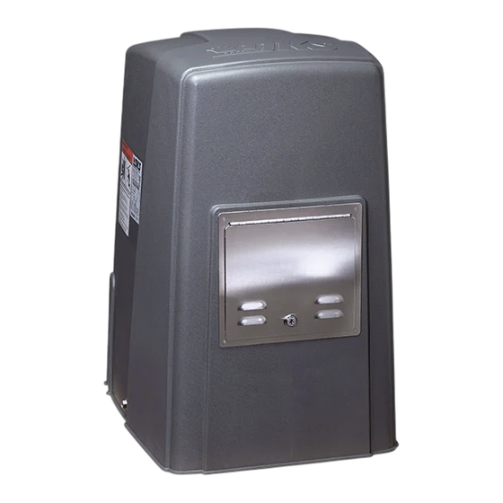
DKS 1600 Series Owner's Manual

Vehicular gate operators with battery backup

Advertisement

Quick Links

Owner's Manual
P/N 2340-065 REV F, 4/04
Copyright 2001 DoorKing, Inc. All rights reserved.
Supplemental Instructions for Series 1600, 6000, 9000
Vehicular Gate Operators with Battery Backup
DoorKing, Inc.
120 Glasgow Avenue
Inglewood, California 90301
Phone: 310-645-0023
Fax: 310-641-1586
www.doorking.com
U.S.A.

Advertisement

Table of Contents
loading

Summary of Contents for DKS 1600 Series

  • Page 1 Owner’s Manual Supplemental Instructions for Series 1600, 6000, 9000 Vehicular Gate Operators with Battery Backup DoorKing, Inc. 120 Glasgow Avenue Inglewood, California 90301 U.S.A. Phone: 310-645-0023 Fax: 310-641-1586 www.doorking.com P/N 2340-065 REV F, 4/04 Copyright 2001 DoorKing, Inc. All rights reserved.
  • Page 2 Page 2...
  • Page 3 Use this manual as a supplement to and with the manuals included in the following models 1601, 1602 Barrier Gate Operators, 6100, 6300 Swing Gate Operators, 9150, 9300, 9310 Slide Gate Operators. DoorKing, Inc. reserves the right to make changes in the products described in this manual without notice and without obligation of DoorKing, Inc.
  • Page 4: Important Notices

    IMPORTANT NOTICES This manual is used as a supplement to the installation instructions that are provided with the vehicular gate operator. This manual references only the battery backup system and its connections to the vehicular gate operator. Refer to the operator installation manual for all other instructions. The optional battery backup system installed in your vehicular gate operator is designed as a convenience enhancement only.
  • Page 5: Operating Modes

    1.1 OPERATING MODES This battery backup system consist of a control board (2340-010), motor and power supply (batteries) providing a completely redundant drive system to open the gate should a power outage occur. This backup system is not designed to maintain continuous gate operation; rather it provides a convenient method to open a gate during adverse conditions.
  • Page 6 1.2 ADJUSTMENTS The DIP-switch located on the battery backup circuit board is used to setup the backup system for the type of operator it is installed in, and to program how the backup system will respond when a power outage occurs. SWITCH FUNCTION SETTING...
  • Page 7: Terminal Description

    1.3 TERMINAL DESCRIPTION COMMON Common terminal for open input and radio receiver connected to the backup board. Note: Radio receiver cannot be connected when the system is installed in a 1601 or 1602 barrier gate operator. OPEN INPUT Input from push button or radio receiver (slide and swing operators only) will activate the gate operator.
  • Page 8 2.1 SWING GATE OPERATORS 2.1.1 SINGLE OPERATOR • For general access applications, be MASTER - 4502 BOARD sure that the auto-open feature is turned on. Set switch 1 to the ON position. • Connect a normally open push-button to terminals 1-2 on the battery backup control board.
  • Page 9 2.1.2 MASTER / SLAVE OPERATORS MASTER - 4502 BOARD SWING GATE SLAVE SLAVE MTR WHITE WHITE BLUE OPEN VIOLET VIOLET YELLOW YELLOW BROWN BROWN ORANGE ORANGE GRAY GRAY MASTER / SLAVE CONDUIT Figure 2 • Wire swing gate master / slave operators as shown in Figure 2. Color code shown assumes the use of DoorKing master / slave cable.
  • Page 10 2.2 MODEL 9150 SLIDE GATE OPERATORS 2.2.1 SINGLE OPERATORS • For general access applications, be SLIDE GATE MASTER sure that the auto-open feature is 4602 BOARD turned on. Set switch 1 to the ON position. • Connect a normally open push-button to terminals 1-2 on the battery backup control board.
  • Page 11 2.2.2 MASTER / SLAVE OPERATORS SLIDE GATE MASTER SLIDE GATE MASTER 4602 BOARD 4602 BOARD YELLOW YELLOW VIOLET VIOLET OPEN BROWN BROWN ORANGE ORANGE NOTE NOTE GRAY GRAY WHITE WHITE BLUE BLUE MASTER / SLAVE CONDUIT Figure 4 • Slide gate systems use two master operators rather than a master-slave combination to create bi-parting slide gates.
  • Page 12 2.3 MODEL 9300 SLIDE GATE OPERATORS 2.3.1 SINGLE OPERATORS • For general access applications, be SLIDE GATE MASTER sure that the auto-open feature is 4402 BOARD turned on. Set switch 1 to the ON position • Connect a normally open push-button to terminals 1-2 on the battery backup control board.
  • Page 13 2.3.2 MASTER / SLAVE OPERATORS SLIDE GATE MASTER SLIDE GATE MASTER 4402 BOARD 4402 BOARD OPEN MASTER / SLAVE CONDUIT Figure 6 • Slide gate systems use two master operators rather than a master-slave combination to create bi-parting slide gates. Wire slide gate master / master operators as shown in Figure 6. Color code shown assumes the use of DoorKing master / slave cable.
  • Page 14 2.4 MODEL 9310 SLIDE GATE OPERATORS 2.4.1 SINGLE OPERATORS SLIDE GATE MASTER 4403 BOARD • For general access applications, be sure White that the auto-open feature is turned on. Green Set switch 1 and 4 to the ON position. • Connect a normally open push-button to terminals 1-2 on the battery backup OPEN...
  • Page 15 2.4.2 MASTER / SLAVE OPERATORS SLIDE GATE MASTER SLIDE GATE MASTER 4403 BOARD 4403 BOARD Brown Brown OPEN Orange Orange Yellow Yellow Limit Limit Gray Limit Gray Limit Mid-Limit Mid-Limit Common Common Common Common MASTER / SLAVE CONDUIT Figure 8 •...
  • Page 16 2.5 BARRIER GATE OPERATORS 2.5.1 SINGLE OPERATORS • The auto-open feature must be turned on BARRIER GATE MASTER 1601 BOARD when the battery backup system is used in the 1601 or 1602 barrier gate operators. Be sure switch 1 is in the ON position. •...
  • Page 17 2.5.2 MASTER / SLAVE OPERATORS BARRIER GATE MASTER BARRIER GATE MASTER 1601 BOARD 1601 BOARD YELLOW YELLOW BROWN BROWN ORANGE ORANGE GRAY GRAY MASTER / SLAVE CONDUIT Figure 10 • Barrier gate systems use two master operators rather than a master-slave combination to create bi-parting barrier gates.
  • Page 18 2.6 RESIDENTIAL APPLICATIONS Battery backup systems used in residential applications may use an RF receiver to open the gate upon a power outage rather than the auto-open feature that is used in general access applications. This allows the residential gate to remain closed until it receives a command to open from the radio receiver.
  • Page 19: Wiring Diagram

    3.1 WIRING DIAGRAM 1601, 1602 Operators Only OPEN LIMIT SWITCH N.O. 9310 Operators Only 7082-305 Wire Assembly ACTIVATION OUTPUT 24 VAC MONITOR COMMON GREEN ON / OFF BLACK WHITE BROWN BROWN WHITE/BLACK BLACK DC MOTOR Figure 12 Part Number Description 2340-010 Control Board 1801-009...

This manual is also suitable for:

6000 series9000 series

Table of Contents