Table of Contents
Advertisement
Quick Links
Download this manual
See also:
Installation Manual
Installation/Owner's Manual
Use this manual for circuit board 1601-010 Revision V or higher.
Date Installed:
Installer/Company Name:
Phone Number:
Leave Manual with Owner
UL 325 Compliant
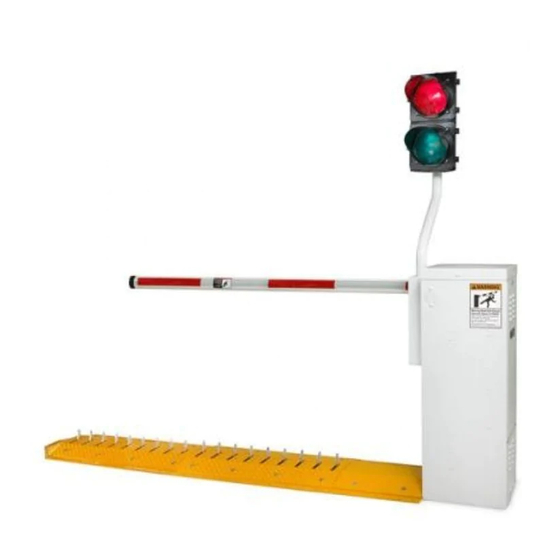
Barrier Gate Operator with Auto Spike System
Circuit Board
Serial Number
and Revision Letter:
Copyright 2011 DoorKing, Inc. All rights reserved.
1603
1603
1603
1603-065-N-7-11
Copyright 2009 DoorKing, Inc. All rights reserved.
TM
Advertisement
Table of Contents

Related Manuals for DKS 1603


Summary of Contents for DKS 1603
- Page 1 Installation/Owner’s Manual 1603 1603 1603 Barrier Gate Operator with Auto Spike System Use this manual for circuit board 1601-010 Revision V or higher. 1603-065-N-7-11 Date Installed: Installer/Company Name: Circuit Board Serial Number Phone Number: and Revision Letter: Leave Manual with Owner Copyright 2011 DoorKing, Inc.
-
Page 3: Specifications
1603 SPECIFICATIONS Use this manual for the Model 1603 operators with circuit board 1601-010 Rev V or higher ONLY. 1603 Housing Class of Operation Model 1601 - UL 325 Class II, III, IV – ETL Listed 14.74” 15.25” Type of Gate... -
Page 4: Table Of Contents
7.3 DIP-Switch Settings SECTION 8 - OPTIONAL ACCESSORIES INSTALLATION 8.1 Contact Sensor (Reversing Edge) 8.2 Fan Kit 8.3 Heater Kit SECTION 9 - TECHNICAL INSTRUCTIONS 9.1 Maintenance Schedule 9.2 Diagnostics Check 9.3 Troubleshooting 32-33 9.4 Accessories Parts List Wiring Schematics 35-38 1603-065-N-7-11... -
Page 5: Safety Information For Vertical Barrier Arm
Pedestrian Walkway Helps increase distance Contact Sensor and time between vehicles. Located so pedestrians Minimizes the potential of the arm closing on vehicular cannot come in contact or other traffic that loops cannot sense. with the barrier arm. 1603-065-N-7-11... -
Page 6: Ul 325 Entrapment Protection
C - Inherent adjustable clutch or pressure relief device. D - Provision for connection of, or supplied with, an actuating device requiring continuous pressure to maintain opening or closing motion of the gate. E - An inherent audio alarm. 1603-065-N-7-11... -
Page 7: Section 1 - Installation Of Operator
We suggest that minimum 3/4-inch conduit be used. Elbow • Never run low voltage rated wire insulation in the same conduit as high voltage rated wire insulation. • Be sure that all conduits are installed in accordance with local codes. 1603-065-N-7-11... -
Page 8: Concrete Pad Requirements
Sections MUST lay flat and level on concrete to operate properly! Sleeve Anchors Embedded Wire Mesh Depth of concrete under the operator is determined by soil conditions and DO NOT mount sections at this time. local building codes. Conduit 1603-065-N-7-11... -
Page 9: Dual Operator Installation (Primary/Secondary)
Interconnection cable: The BROWN wire must be connected to SECONDARY TERMINAL #9 along with the GRAY wire. All other terminal wire connections are the same as shown above. Secondary Illustration shows six 3-ft spike sections (18 ft. of spikes). Operator Each operator controls three 3-ft spike sections. 1603-065-N-7-11... -
Page 10: Section 2 - Wiring
3-phase power. DO NOT power up and cycle the operator until the “DIP-Switches” have been set for the 1603 model (See pages 20 and 21). The operator will not function properly unless the High Voltage High Voltage switches have been correctly set. -
Page 11: Main Terminal Description
SW 1 When switch 4 is OFF, this input is identical to the reverse input, input will reverse the arm to the up terminal 9. position. 1603-065-N-7-11... -
Page 12: Control Wiring
Contact Sensor (Reversing Edge) See page 28 Non-Contact Sensor (Photo Sensors) Contact and Non-Contact Sensors Note: 21” Typical Beam Height. Helps minimizes the potential of the arm 27.5” Max. Beam Height. lowering on vehicular or other traffic that loops cannot sense. 1603-065-N-7-11... -
Page 13: Section 3 - Installation Of Auto Spike System
3.1 Lay Sections on Concrete Pad Lay all tunnel plates on the concrete pad in their final configuration. Plates must lay flat on the concrete and be level with each other. DO NOT anchor them to the concrete at this time. 1603-065-N-7-11... -
Page 14: Assemble Shafts
Spikes should rotate 90° into Arm DOWN operation, some tunnel plate when operator cycles adjustment will be the arm to the UP position. required. See 3.3a on the next page. n t a r i z o 1603-065-N-7-11... -
Page 15: Secure Tunnel Plates And Ramps To Concrete
3/8” x 3” sleeve anchors (Not supplied). Install ramps on tunnel plates with flathead bolts provided. Secure ramps and end cap to concrete with 3/8” x 3” sleeve anchors (Not supplied) Cut off excess threads flush with top of nut. 1603-065-N-7-11... -
Page 16: Section 4 - Loop Detector Lane Setups
The arm will remain UP. Timer will time out and lower the arm without the down loop being activated. 1603-065-N-7-11... -
Page 17: Exit Lane Only
Activation of the down loop will cancel timer countdown. Useful when the automatic exit loop has been activated but vehicle does not move forward to activate the down loop. The arm will remain UP. Timer will time out and lower the arm without the down loop being activated. 1603-065-N-7-11... -
Page 18: 2-Way Traffic Lane
Helps increase distance move forward to activate the down loop. The arm will remain UP. Timer will and time between vehicles. time out and lower the arm without the down loop being activated. 1603-065-N-7-11... -
Page 19: Ticket Spitter Entry Lane
The arm will remain UP. Timer will time out Helps increase distance and lower the arm without the down loop being activated. and time between vehicles. 1603-065-N-7-11... -
Page 20: Operator Timer On Entry Lane (No Down Loop)
Reverse Loop Note: The reverse loops will prevent the arm from closing on a Speed Bump vehicle remaining in the arm’s pathway. The timer will restart the countdown any Helps increase distance time the reverse loop gets activated. and time between vehicles. 1603-065-N-7-11... -
Page 21: Section 5 - Arm Installation
IF IE 2 . 2 Note: To install folding aluminum arm, R IA refer to instruction sheet supplied in aluminum folding arm kit. P/N 1601-310 o r K in g , In c . , In g le w 1603-065-N-7-11... -
Page 22: Section 6 - Adjustments
Normally Open (NO) or Normally DOWN direction of Closed (NC) operation by placing the relay arm. shorting bar on the N.O. or N.C. pins See page 24. respectively. See page 9 and next page. Min Max 1603-065-N-7-11... -
Page 23: Dip-Switch Sw 1 And Sw 2 Settings
Description Model 1603 Switch must be OFF for model 1603 barrier gate operator. Normal setting. Operator will respond to a single UP command, then require a DOWN command. Operator will not accept multiple Up commands. Operator will not accept the next UP command until Multiple Input Memory the previous DOWN command is in progress. - Page 24 “Next Car’s” down loop to be activated. 1st Car Next Car When “Next Car” activates then clears Note: down loop, arm will lower. If an UP command is given while the arm is lowering, the arm will raise. 1603-065-N-7-11...
- Page 25 Note: If an UP command is given while the arm is lowering, the arm will raise. Valid UP command given Access Control Device 1603-065-N-7-11...
-
Page 26: Magnetic Limit Adjustment
1/8 turn. REVERSE 1601 SENSITIVITY POWER Repeat the adjustment as needed to find a SW 2 satisfactory setting. REVERSE SENSITIVITY DOWN LOOP Min Max NC NO 1 2 3 4 5 6 7 8 9 10 11 12 13 14 1603-065-N-7-11... -
Page 27: Manual Operation Of Arm And Spikes
Rotate crank tool to manually move operator arm and spikes up or down. e r l o c e s b l y I n t s e m T o o C r a r a g S t o 1603-065-N-7-11... -
Page 28: Section 7 - Optional Convenience Open System
“manual input” (switch 3 OFF) before the operator DIP-Switches resumes normal operation. Initial Power Up Convenience Open Note: The DC power is not present on the main circuit board until the first initial cycle. 1603-065-N-7-11... -
Page 29: Dc System Description
Power-up When AC power is restored, a 1-second pulse is sent to the gate operator input to Activation automatically restore normal operation. Operator Type Must be in the ON position. Not Used Not Used Not Used Not Used 1603-065-N-7-11... -
Page 30: Section 8 - Optional Accessories Installation
In c. , In gl ew Connect wires to terminals 9 and using wire ties (not supplied). leave Wire Loop 14 without interfering with any of a wire loop to allow the arm to the operator’s moving parts. rotate freely. 1603-065-N-7-11... -
Page 31: Fan Kit
ON when the temperature rises above 90°F inside the S t a E x i housing, and turns the fan OFF when the temperature A i r drops below 90°F. Keep intake vents clear of debris. 1603-065-N-7-11... -
Page 32: Heater Kit
ON when the temperature drops below 40°F inside the housing, and turns the heater OFF when the temperature rises above 40°F inside the housing. - Turns the heater off. - Turns the heater on continuously. The heater will become VERY HOT when running continuously. 1603-065-N-7-11... -
Page 33: Section 9 - Technical Instructions
Check set screw for tightness. ✓ ✓ Check electric reversing edges and photo-cells for proper Secondary Reverse Device(s) operation. ✓ Perform a complete system check. Include all reversing devices, Complete System loops, access system devices, Fire Dept. access devices, etc. 1603-065-N-7-11... -
Page 34: Diagnostics Check
• Check for 117 VAC with a voltmeter at control board terminals 1 and 2. If voltage measures 0, Power LED is OFF. check power supply to operator or check terminal strip. If voltage measures OK, replace control board. 1603-065-N-7-11... - Page 35 Check to be sure that the 2340-010 battery back-up control board switch settings are set as system will not described in SECTION 7. raise arm upon • Check the batteries for proper voltage, replace if necessary. power outage. • Replace the 2340-010 Back-up control board. 1603-065-N-7-11...
-
Page 36: Accessories Parts List
1838 access control system. Auto Spike System Parts 2 Ft Extension Section - 2 Ft extension shaft, tunnel plate and ramps. P/N 1603-192 3 Ft Extension Section - 3 Ft extension shaft, tunnel plate and ramps. P/N 1603-193 3 Ft Spike Section - 3 Ft spike shaft, tunnel plate and ramps. P/N 1603-073... -
Page 37: Wiring Schematics
Limit Sensor 1601 POWER REVERSE SENSITIVITY DOWN LOOP NC NO Current Sensor 1 2 3 4 5 6 7 8 9 10 11 12 13 14 Chassis Ground Power NEU HOT 115 VAC Neutral Yellow Orange Ground AC Power UP/Auto/Down 1603-065-N-7-11... - Page 38 Current Sensor 1 2 3 4 5 6 7 8 9 10 11 12 13 14 Chassis Ground Power NEU HOT 115 VAC Neutral Purple Green White Orange Yellow Yellow Orange Purple Red/White Blue Ground AC Power DC Power UP/Auto/Down 1603-065-N-7-11...
- Page 39 1 2 3 4 5 6 7 8 9 10 11 12 13 14 Chassis Ground Power 230 / 460 VAC Neutral Yellow Orange Purple Blue To White Blue Black To Blue Brown White Black/White Blue Blue To White Blue Black Brown To Blue Ground White Black/White AC Power UP/Auto/Down 1603-065-N-7-11...
- Page 40 230 / 460 VAC Neutral Purple Green White Orange Yellow Yellow Orange Purple Red/White Blue To White Blue Black To Blue Brown White Black/White Blue Blue To White Blue Black Brown To Blue Ground White Black/White AC Power DC Power UP/Auto/Down 1603-065-N-7-11...
- Page 41 1603-065-N-7-11...
-
Page 42: 1603-065
Installation/Owner’s Manual 1603 1603 1603 Barrier Gate Operator with Auto Spike System Use this manual for circuit board 1601-010 Revision V or higher. 1603-065-N-7-11 www.doorking.com DoorKing, Inc. 120 Glasgow Avenue Inglewood, California 90301 U.S.A. Phone: 310-645-0023 Fax: 310-641-1586 Copyright 2009 DoorKing, Inc. All rights reserved.
Need help?
Do you have a question about the 1603 and is the answer not in the manual?
Questions and answers