Table of Contents
Advertisement
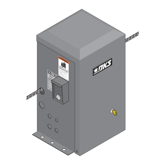
Installation/Owner's Manual
Use this manual for circuit board 4602-010 Revision A or higher.
Date Installed:
Installer/Company Name:
Phone Number:
Leave Manual with Owner
UL 325 Compliant
W A
R N
I N
G
M O
V I N
S E
R I
G
O U
G A
S I
T E
O p
N J
e ra
C A
a n
te
U R
d fr
g a
N
te
e e
Y O
C A
o f
o n
D o
p e
ly
U S
w h
R D
n o
o p
E
o r
t a
le
e n
E A
o p
ll o
a n
g a
e ra
w
d o
te
T H
te
c h
b s
a re
D o
g a
il d
tr u
a is
te .
re n
c ti
n o
in
p a
t s
to
o n
s ig
th
ta n
p la
s .
w h
h t
d in
y in
il e
R e
g a
g a
g a
a d
te
te
te
is
p a
a re
C O
o w
N F
n e
m o
th
a
r' s
v in
o r
A N
O R
w a
m a
g .
S I/
M S
lk
n u
th ro
U L
T O
a l
-3 2
a n
u g
C A
C E
d s
h
5
N /C
R T
a fe
IF IE
ty
S A
in s
D
V E
C 2
tr u
2 .2
T O
c ti
H IC
o n
N O
U L
s .
C L
. 2
53
A R
38
A S
4 7
2
S
G A
T E
M O
O P
D E
E R
L
A T
S E
O R
H P
R IA
L
V O
L T
S
A M
P S
M A
X G
P H
A S
A T
E L
E
O A
D o
D
6 0
o rK
H z
in g
, In
c .,
In g
le w
o o
d ,
C A
Circuit Board
Serial Number
and Revision Letter:
Copyright 2010 DoorKing, Inc. All rights reserved.
Model 9100
Model 9100
Model 9100
Vehicular Slide Gate Operator
Copyright 2009 DoorKing, Inc. All rights reserved.
9100-065-S-11-10
TM
Advertisement
Table of Contents
Troubleshooting

Subscribe to Our Youtube Channel
Related Manuals for DKS 9100


Summary of Contents for DKS 9100
- Page 1 Model 9100 Model 9100 Model 9100 Installation/Owner’s Manual Vehicular Slide Gate Operator Use this manual for circuit board 4602-010 Revision A or higher. 9100-065-S-11-10 V I N e ra d fr ll o e ra a re il d tr u a is te .
-
Page 3: Specifications
Vehicular Slide Gates Only Horsepower 1/2 HP Voltage / Phase 115 VAC Single-Phase Use this manual for the Model 9100 Current 5.4 Amps @ 120V operator with circuit board 4602-010 Rev A or higher ONLY. Max Gate Weight (Installed level) 1000 Lbs. -
Page 4: Table Of Contents
1.9 Chain Tray Kit SECTION 2 - AC POWER TO OPERATOR(S) 2.1 High Voltage Wire Runs 2.2 High Voltage Terminal Connection SECTION 3 - ADJUSTMENTS 3.1 4602 Circuit Board Description and Adjustments 3.2 DIP-Switch SW 1 and SW 2 Settings 22-23 9100-065-S-11-10... - Page 5 Soft Shutdown Hard Shutdown 6.3 Manual Gate Operation 31-37 Fail-Safe Manual Release System Fail-Secure Manual Release System Emergency Vehicle Access Conditions SECTION 7 - MAINTENANCE AND TROUBLESHOOTING 7.1 Maintenance 7.2 Troubleshooting 39-40 7.3 Accessory Items Model 9100 Wiring Diagram 9100-065-S-11-10...
-
Page 6: Astm 2200 Standard For Gate Construction
2. Care shall be exercised to reduce the risk of nuisance tripping, such as when a vehicle trips the sensor while the gate is still moving in the opening direction. 3. One or more non-contact sensors shall be located where the risk of entrapment or obstruction exist, such as the perimeter reachable by a moving gate or barrier. 9100-065-S-11-10... -
Page 7: Important Notices
Do not allow children to play in the area of the operator or to play with any gate-operating device. • To remove the gate operator from service, operate the gate to the full open position and then shut off power to the operator at the service panel. 9100-065-S-11-10... -
Page 8: Ul325 Entrapment Protection
C - Inherent adjustable clutch or pressure relief device. D - Provision for connection of, or supplied with, an actuating device requiring continuous pressure to maintain opening or closing motion of the gate. E - An inherent audio alarm. 9100-065-S-11-10... -
Page 9: Glossary
ENTRAPMENT - The condition when an object is caught or held in a position that increases the risk of injury. 9100-065-S-11-10... -
Page 10: Slide Gate Requirements
AND A contact sensor should non-compliant be installed in this area adjacent fence for safety. that covers (See open gate on next position page). (See above). Less than 2 1/4” Screened Wire Mesh Gate Frame and Adjacent Fence Area 9100-065-S-11-10... -
Page 11: Slide Gate Protection
Do not let children operate the gate or play in the gate area. This entrance is for vehicles only. Separate Pedestrians must use separate entrance. Pedestrian Walkway Located so pedestrians cannot come in contact with the vehicular gate. 9100-065-S-11-10... -
Page 12: Section 1 - Installation
1.2 Physical Stops for the Gate Rubber bumper faces toward The 9100’s automatic open/close gate limits must have a physical operator. it will make contact stop on the open and close positions of the gate. This can be the... -
Page 13: Typical Gate Types
1.3 Typical Gate Types The Model 9100 operator is designed to be installed on these gate types. See the next 4 pages for specific operator mounting positions. Individual installations and physical stops can vary. • 1000 lb. max. weight per gate. -
Page 14: Operator Mounting Positions
1.4 Operator Mounting Positions The Model 9100 operator is designed to be installed in the front, rear, center or ceiling mounting positions shown on this page and the next 3 pages. V-wheel V-rail ornamental gates are shown as examples but other gate types on the previous page can use the same mounting setups. - Page 15 Rear Position with Post Mount Hides the chain from outside the property looking in. • Chain setup is the same as above. Additional hardware required. Post base plate (P/N 2600-418) 4 x 4 steel posts not available from DoorKing. 9100-065-S-11-10...
- Page 16 Gate shown in open position. Optional chain tray kit (P/N 2601-270) can Optional Chain Tray Kit be used and is recommended for gates over for Long Gates Gate in Open Position 20 ft, see page 19 for more information. 9100-065-S-11-10...
-
Page 17: Underground Conduit Requirements
Sweep • DoorKing recommends using 3/4-inch conduit. Elbow • Be sure that all conduits are installed in accordance with local codes. • Never run low voltage rated wire insulation in the same conduit as high voltage rated wire insulation. 9100-065-S-11-10... -
Page 18: Pad, Post Or Ceiling Mount Without/With J-Box Setup
DoorKing, Inc., Inglewood, CA same conduit. Fail-Secure Operator MUST Key Lock be level. High High Volt Volt Volt Volt Note: Operator must be mounted Conduit Knock-Out Sizes Pad, post or 1” min. away from gate. ceiling mount Conduit Conduit 9100-065-S-11-10... -
Page 19: Mounting Operator And Chain
Washer tighten the chain. The chain should sag no Use six (6) 1/2”-13 x 1 1/2” Washers more than one (1) inch per 10 feet of travel. bolts, lockwashers and nuts Do not over tighten the chain. (not supplied). 9100-065-S-11-10... -
Page 20: Installation Of Warning Signs
Endless Idler Assembly (On Select Installations) DoorKing offers an endless idler assembly with a protective cover designed for the Model 9100 installations (P/N 2600-818). Make sure the endless idler assembly is securely fastened to the wall or post (Depending on which type of installation will be used). -
Page 21: Chain Tray Kit
(1) inch per 10 feet of travel. Post base plate (P/N 2600-418) Base Plate Stop Brackets (P/N 2600-970) when using chain stops. Chain Tray Supporting Note: All gate types can have Bracket the chain tray installed on them, V-rail V-wheel ornamental is shown here. 9100-065-S-11-10... -
Page 22: Section 2 - Ac Power To Operator(S)
Wire Size / Distance in Feet 12 AWG 10 AWG 8 AWG 6 AWG Single 9100: 5.4 Amp Motor Dual 9100’s, Single Power Source 2.2 High Voltage Terminal Connection • Route incoming AC power wire through the high voltage conduit and run wire in the operator as shown. -
Page 23: Section 3 - Adjustments
Whenever any of the programming switches on the circuit board are changed, power must be shut-off, and then turned back on for the new setting to take effect. Every time the 9100 is powered up, the First open command will automati- cally run “Multiple gate cycles”... -
Page 24: Dip-Switch Sw 1 And Sw 2 Settings
1, 2 or 3 inches short of the full open position. Needed only when using a reversing edge entrapment protection device on the opening edge of the gate with an end post as the physical stop. 9100-065-S-11-10... - Page 25 Normal Setting. Switch must be OFF for terminal #5 input to open gate 14 Ft. Partial Open (14 Ft) DO NOT use ON setting. NOT associated with partial open feature for the 9100. Normal Setting. Fail-safe logic. Lock engages only if attempt is made to force gate Built-in open (Factory setup).
-
Page 26: Automatic Open / Close Limit Adjustment
3.3 Automatic Open / Close Limit Adjustment The 9100’s open/close limits DO NOT have to be physically adjusted. Every time the 9100 is powered up, the first open command will automatically run “Multiple gate cycles” that will locate and remember the gate’s open and close positions. -
Page 27: Clutch Adjustment
If it does not, increase the reverse sensitivity (step ) and repeat this test until the correct sensitivity has been set. The operator will assume a soft shutdown after striking and reversing the gate which will require a key switch command to cycle operator again. 9100-065-S-11-10... -
Page 28: Section 4 - Entrapment And Safety Protection
Secondary Entrapment Protection Devices: In addition to the inherent reversing sensor system, the Model 9100 has a 5-pin UL 325 terminal for the connection of photo sensors-Type B1 and reversing edges-Type B2 secondary entrapment protection devices required by UL 325 standards. Entrapment protection devices must be installed to reduce the risk of injury. -
Page 29: Secondary Entrapment Protection Device Locations
See pages 30 and 31 4602 for more information. Photo Sensor Power Note: Photo sensors can be powered by the built-in Common convenience outlets located on the operator (See previous page). 9100-065-S-11-10... - Page 30 When a reversing edge or photo beam get 24 VAC Receiver Terminal obstructed the gate will STOP, then continue Normally Open in the same direction after obstructed Place receiver in operator. Common reversing edge or photo beam has been cleared until the gate cycle is complete. 9100-065-S-11-10...
-
Page 31: Loop Detector Wiring
Note: Loop detector wiring is shown for DoorKing plug-in loop detector P/N 9410-010 (Single Channel) only. If other loop detectors are used, refer to the installation instructions supplied with those detectors for wiring and REVERSE separate power instructions. SENSITIVITY 9100-065-S-11-10... -
Page 32: Section 5 - Wiring
Contact rating is 1 amp maximum at 24-volts DC. SW 1 Provides 24 VDC, 250 ma. maximum to power LED. Operation of LED is dependent on setting of SW 1, switches 4 and 5 (See page 22). SW 1 9100-065-S-11-10... -
Page 33: Control Wiring For Single/Primary Operator
Secondary entrapment protection devices will also must be devices must use a open the gate to the partial open setting. If the OFF. Inherent Reverse Sensor gets activated during the separate power close cycle, it will always fully open the gate. source. SW 2 9100-065-S-11-10... -
Page 34: Auxiliary Device Wiring
For more detailed information refer to the Tracker Installation and Wiring Manual, DoorKing P/N 2351-010. Terminal #4 (Full open) or #5 (14-Ft. open) required only if the tracker board will activate the gate operator. Refer to the manual 2351-065 for detailed information. 9100-065-S-11-10... -
Page 35: Bi-Parting Gates Wiring - Dual Gate Operators
Automatic Orange Orange Exit Loop 4602 4602 Gray Blue Blue Gray Interconnection Cable Sold separately from DoorKing. 6 wires used (8 - 18 AWG wires total). Dual Channel 9409 Plug into Primary Operator Exit Loop Port 9100-065-S-11-10... -
Page 36: Section 6 - Operating Instructions
ON (toggle up) or OFF (toggle down). Every time the 9100 is powered up, the First open command will automatically run “Multiple gate cycles” that will locate and remember the gate’s open and close positions (See page 24). 9100-065-S-11-10... -
Page 37: Shutdown Conditions
To silence the alarm, press the reset button or after 5 minutes, the audio alarm will shut off but will “chirp” every 5 seconds. This indicates that the operator is in a hard shutdown condition (The reset button must be pressed to reset the operator and stop the alarm “chirping”). 9100-065-S-11-10... -
Page 38: Manual Gate Operation
Solenoid lock WILL retract and secure the clutch plate during AC power failure or turning AC power off. Gate can be normal operation ONLY if operator senses an unauthorized immediately manually operated during these conditions. manual open attempt. Gate will NOT be allowed to move. 9100-065-S-11-10... -
Page 39: Fail-Secure Manual Release System
2. In the event of an AC power failure, the emergency vehicle access device will not function because the gate operator is un-powered. “Fail-Safe” or “Fail-Secure” release systems for the 9100 allow the gate to be manually operated during AC power failure. ONLY the “Fail-Safe” release system allows the gate to be manually operated without unlocking the operator first and has been designed that way to allow emergency personnel to immediately manually operate the gate from either side under emergency situations. -
Page 40: Section 7 - Maintenance And Troubleshooting
Keeping this operator in service when the inherent reversing system is malfunctioning Every time the 9100 is powered up, the First open creates a hazard for persons which can result in serious injury or command will automatically run “Multiple gate death should they become entrapped in the gate. -
Page 41: Troubleshooting
If the motor runs in both steps above, replace the control board. If the motor does not run, or runs in only one direction, problem can be a bad motor, motor capacitor, motor resistors, wire connections from the control board to the motor or a bad control board. 9100-065-S-11-10... - Page 42 • Operator has been in a “hard shutdown” condition in excess of 5 minutes. Reset button must be every 5 seconds. pushed to return operator to normal operation, see Section 6.2 Shutdown Conditions, pages 35-36. Operator will not run. 9100-065-S-11-10...
-
Page 43: Accessory Items
7.3 Accessory Items The following accessory items are available for the model 9100 slide gate operator. Contact Sensors - For use as a secondary entrapment protection device. Miller Edge, Inc., MGO20, MGR20, MGS20 Photo Cell - Non-contact (photocell) sensors for use as a secondary entrapment protection device. -
Page 44: Model 9100 Wiring Diagram
Model 9100 1/2 HP 115 VAC 1/2 HP 50uf Capacitor Blue Convenience Outlets Ground Black Motor Resistors White Power Neutral Blue 1 Ohm 1 Ohm White Blue Black 30 Watt 30 Watt Purple Black MOV Assembly White White Chassis 115 VAC... -
Page 46: 9100-065
Model 9100 Model 9100 Model 9100 Installation/Owner’s Manual Vehicular Slide Gate Operator Use this manual for circuit board 4602-010 Revision A or higher. 9100-065-S-11-10 www.doorking.com DoorKing, Inc. 120 Glasgow Avenue Inglewood, California 90301 U.S.A. Phone: 310-645-0023 Fax: 310-641-1586 9100-065-N-5-10 Copyright 2009 DoorKing, Inc. All rights reserved.
Need help?
Do you have a question about the 9100 and is the answer not in the manual?
Questions and answers