Table of Contents
Advertisement
Quick Links
Installation/Owner's Manual
Use this manual for circuit board 1601-010 Revision V or higher.
1 6 0
2
Date Installed:
Installer/Company Name:
Phone Number:
Leave Manual with Owner
UL 325 Compliant
Circuit Board
Serial Number
and Revision Letter:
Copyright 2013 DoorKing, Inc. All rights reserved.
1601 / 1602
1601 / 1602
1601 / 1602
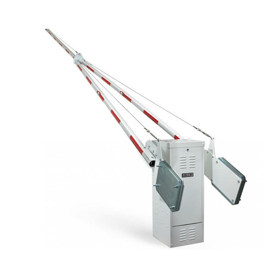
Barrier Gate Operator
1601-065-L-3-13
CON
ANS
FOR
I/UL
MS
TO
CAN
CER
-32
5
/CS
A C22
TIF
IED
VE
HIC
.2
TO
CLA
UL
AR
NO
. 247
5338
SS
GA
2
MO
TE
OP
DEL
ER
ATO
SER
HP
R
IAL
VOL
TS
AM
PS
MA
PHA
X GAT
SE
Doo
E LOA
60
rKin
D
Hz
g,
Inc.
, Ing
lew
ood
, CA
1 6 0
1
Copyright 2009 DoorKing, Inc. All rights reserved.
TM
Advertisement
Table of Contents

Related Manuals for DKS 1601


Summary of Contents for DKS 1601
- Page 1 1601 / 1602 1601 / 1602 1601 / 1602 Installation/Owner’s Manual Barrier Gate Operator Use this manual for circuit board 1601-010 Revision V or higher. 1601-065-L-3-13 1 6 0 I/UL A C22 . 247 5338 X GAT E LOA rKin Inc.
-
Page 3: Table Of Contents
4.1 Mounting Hub 4.2 Mounting Arm 4.3 1602 3-Piece Arm Assemblies SECTION 5 - ADJUSTMENTS 5.1 1601 Circuit Board Description and Adjustments 5.2 DIP-Switch SW 1 and SW 2 Settings 22-24 5.3 Reverse Arm UP and DOWN Positions 5.4 Magnetic Limit Adjustment 5.5 Reverse Sensor Adjustment... -
Page 4: Specifications
1601 SPECIFICATIONS Use this manual for the Model 1601 operators with circuit board 1601-010 Rev V or higher ONLY. 1601 Housing 14.74” 15.26” Class of Operation Model 1601 - UL 325 Class II, III, IV – ETL Listed Type of Gate... - Page 5 1602 SPECIFICATIONS Use this manual for the Model 1602 operators with circuit board 1601-010 Rev V or higher ONLY. 1602 Housing 15.74” 15.26” Class of Operation Model 1602 - UL 325 Class III, IV – ETL Listed Type of Gate...
-
Page 6: Safety Information For Vertical Barrier Arm
Contact your service dealer for any maintenance or repairs. • Vehicular operators can produce high levels of force, it is important that you are aware and eliminate possible HAZARDS; Pinch Points, Entrapment Areas, Overhead Power Wires, Absence of Controlled Pedestrian Access, Traffic Backup. 1601-065-L-3-13... - Page 7 Contact Sensor No higher than 27.5” above grade. Minimizes the potential of the arm 21” is typical for most installations. lowering on vehicular or other traffic that loops cannot sense. Speed Limit Sign Helps control traffic. 1601-065-L-3-13...
-
Page 8: Ul325 Entrapment Protection
C - Inherent adjustable clutch or pressure relief device. D - Provision for connection of, or supplied with, an actuating device requiring continuous pressure to maintain opening or closing motion of the gate. E - An inherent audio alarm. 1601-065-L-3-13... -
Page 9: Section 1 - Installation
Sweep • DoorKing recommends using 3/4-inch conduit. Elbow • Be sure that all conduits are installed in accordance with local codes. • Never run low voltage rated wire insulation in the same conduit as high voltage rated wire insulation. 1601-065-L-3-13... -
Page 10: New Concrete Pad
X GA , CA for mounting operator. secured in place. e s s A c c 4 ” h e i i n . The operator(s) should be installed with the access door of the operator opposite the traffic lane. 1601-065-L-3-13... -
Page 11: Section 2 - Wiring
External Power DO NOT power up and cycle the operator until the Disconnect “DIP-Switches” have been set for the 1601 OR 1602 Switch model (See pages 21 and 22). Note: A separate power disconnect The operator will not function properly unless the switch may be needed in your area. -
Page 12: Dual Gate Operators (Primary/Secondary)
LOOP SW 1 SW 1, switch 4 is ON. SW 1, switch 5 is OFF. SW 1, switch 8 is OFF. Set other DIP-switches 1601 1601 POWER POWER based on gate operation preferences (See page 22). Set both operators DIP-switches... -
Page 13: Main Terminal Description
Function is dependent on the setting This input is used when sequencing the of programming SW 1, switch 8. 1601 with a slide or swing gate operator in When switch 8 is ON, the PAMS applications. This input is only active function of this input is after a MOMENTARY UP input is received. -
Page 14: Control Wiring
For more detailed information refer to the Tracker Installation and Wiring Manual, DoorKing P/N 2351-010. Terminal 6 required only if the tracker board will activate the gate operator. Refer to the manual 2351-065 for detailed information. 1601 POWER LA Y REVERSE... -
Page 15: Multiple Gate Operator Sequencing
DoorKing slide or swing gate operator. For detailed PAMS wiring information, refer to the PAMS Technical Information and Wiring Manual. Operators are wired to each other to sequence their open and close cycles. Operators are wired to each other to sequence their open and close cycles. 1601-065-L-3-13... -
Page 16: Section 3 - Loop Detector Lane Setups
LOOP SW 1, switch 7 is OFF (Timer). The arm will rotate down after the vehicle clears the down loop. See timer SW 1 note below. SW 1 1601 POWER SW 2 Down Loop REVERSE SENSITIVITY DOWN LOOP NC NO... -
Page 17: Exit Lane Only
SW 1, switch 7 is OFF (Timer). The arm will rotate down after the vehicle clears the down loop. See note below. Single Channel SW 1 TIME DELAY LOOP 9410 SW 1 1601 Speed Bump POWER Helps increase distance SW 2 and time between vehicles. REVERSE SENSITIVITY Automatic DOWN... -
Page 18: 2-Way Traffic Lane
Spacing between loops is critical TIME when using this configuration. Be DELAY sure that the loops are spaced as shown in the diagram. LOOP Interior Down Loop 9410 SW 1 1601 POWER 4 Ft. SW 2 Speed Bump REVERSE SENSITIVITY Automatic DOWN Exit Loop... -
Page 19: Ticket Spitter Entry Lane
SW 1, switch 7 is OFF (Timer). The arm will rotate down after the vehicle clears the down loop. See note below. SW 1 TIME DELAY LOOP SW 1 1601 POWER SW 2 REVERSE SENSITIVITY DOWN LOOP NC NO 9409... -
Page 20: Operator Timer On Entry Lane (No Down Loop)
SW 1, switch 7 is ON (Timer). The arm will seconds (full clockwise). lower after the timer has timed out. SW 1 TIME DELAY LOOP SW 1 1601 POWER Reverse Loop SW 2 REVERSE SENSITIVITY Note: Make sure that a vehicle DOWN... -
Page 21: Section 4 - Arm Installation
Arm installation varies depending on the operator model and individual installation requirements. All operators are equipped with 2 hub connections on opposite sides of the operator. The 1601 operates with a single 14 ft. arm (either straight or folding arm). The 1601 can not operate with the 20 ft. to 27 ft. 3-piece arm assemblies. -
Page 22: Mounting Arm ( S )
Damage could occur to operator. Connect the 3 arms weights. together with 3 bolts. Connect weights together with 6 bolts on each arm. 20 Ft. Wood Arm Assembly 1601-065-L-3-13... -
Page 23: Section 5 - Adjustments
Whenever any of the programming switches on the circuit board are changed, power must be shut-off, and then turned back on for the new setting to take effect. 5.1 1601 Circuit Board Description and Adjustments How LEDs Function Auto Close Timer... -
Page 24: Dip-Switch Sw 1 And Sw 2 Settings
Setting Description Model 1601 Switch must be OFF for model 1601 barrier gate operator. Model 1602 Switch must be ON for model 1602 barrier gate operator. Normal setting. Operator will respond to a single UP command, then require a DOWN command. - Page 25 “Next Car’s” down loop to be activated. Next Car 1st Car When “Next Car” activates then clears Note: down loop, arm will lower. If an UP command is given while the arm is lowering, the arm will raise. 1601-065-L-3-13...
- Page 26 Note: If an UP command is given while the arm is lowering, the arm will raise. Valid UP command given Access Control Device 1601-065-L-3-13...
-
Page 27: Reverse Arm Up And Down Positions
Slide the DC limit assembly down the linking arm to align with the DC limit sensor when the arm is in the UP position. Note: DC limit sensor is used to hold the arm in the UP position during an AC power failure. 1601-065-L-3-13... -
Page 28: Magnetic Limit Adjustment
Tighten nuts when desired positions are achieved. Limit Assembly D O W (White Dot)* TIME DELAY UP Limit 1601 L i m DOWN Limit Magnetic Limit LOOP Sensor Down *Factory Magnet Setting 5.5 Reverse Sensor Reverse sensitivity adjustment will cause the barrier arm to reverse direction of travel should an object be encountered during the down cycle. -
Page 29: Manual Operation Of The Arm
“Optional” Manual Release Kit DoorKing offers a kit designed to be installed on the 1601 or 1602 barrier gate operators WITHOUT the convenience open feature. It provides a crank tool to manually move the arm up or down. DO NOT install on convenience open models. For further information about this kit, refer to the instruction sheet provided with the kit (P/N 1601-270) or go to DoorKing’s... -
Page 30: Section 6 - Optional Convenience Open System
“manual DIP-Switches input” (switch 3 OFF) before the operator resumes normal operation. Initial Power Up Convenience Open Note: The DC power is not present on the main circuit board until the first initial cycle. 1601-065-L-3-13... -
Page 31: Dc System Description
Power-up When AC power is restored, a 1-second pulse is sent to the gate operator input to Activation automatically restore normal operation. Operator Type Must be in the ON position. Not Used Not Used Not Used Not Used 1601-065-L-3-13... -
Page 32: Section 7 - Optional Accessories Installation
LOOP v e r s i n s s e SW 1 POWER SW 2 1601 REVERSE SENSITIVITY DOWN LOOP T i e NC NO Install a plastic grommet (Not supplied) in the hole to protect the wire... -
Page 33: Fan Kit
7.2 Fan Kit Threaded Housing Studs An optional fan kit (P/N 1601-093) is recommended in hot humid (Existing) climates to prevent heat and moisture build-up inside the housing. Shut off AC power to operator. Turn off DC power switch on certain models. -
Page 34: Heater Kit
7.3 Heater Kit To avoid the gearbox oil from freezing an optional heater kit (115 VAC - P/N 1601-092) is recommended in areas where temperatures routinely drop below 40°F (4°C). Washer Shut off AC power to operator. Mount heater with 2 lock nuts. -
Page 35: Section 8 - Technical Instructions
Check set screw for tightness. ✓ ✓ Check electric reversing edges and photo-cells for proper Secondary Reverse Device(s) operation. ✓ Perform a complete system check. Include all reversing devices, Complete System loops, access system devices, Fire Dept. access devices, etc. 1601-065-L-3-13... -
Page 36: Diagnostics Check
• Check for 117 VAC with a voltmeter at control board terminals 1 and 2. If voltage measures 0, Power LED is OFF. check power supply to operator or check terminal strip. If voltage measures OK, replace control board. 1601-065-L-3-13... - Page 37 Check to be sure that the 2340-010 battery back-up control board switch settings are set as system will not described in SECTION 6. raise arm upon • Check the batteries for proper voltage, replace if necessary. power outage. • Replace the 2340-010 Back-up control board. 1601-065-L-3-13...
-
Page 38: Accessories Parts List
50 ft. - P/N 2600-757 High Voltage Kit - Alter the input AC voltage on a 115 VAC 1601/1602 to 208, 230, 460 or 575 VAC. P/N 2600-266 Reverse Edge - Installs on the bottom of the arm. P/N 8080-016 - 6 ft. Available from DoorKing to fit all arm lengths. -
Page 39: Wiring Schematics
1/2 or 1 HP 115 VAC Up Limit Magnet TIME DELAY Magnetic LOOP Limit Sensor 1601 POWER REVERSE SENSITIVITY DOWN LOOP NC NO Current Sensor 1 2 3 4 5 6 7 8 9 10 11 12 13 14 Chassis Ground... - Page 40 1/2 or 1 HP 115 VAC / Convenience Open Up Limit Magnet 2340 TIME DELAY Magnetic LOOP Limit Sensor 1601 POWER REVERSE SENSITIVITY DOWN LOOP Black Black/White NC NO Current Sensor 1 2 3 4 5 6 7 8 9 10 11 12 13 14...
- Page 41 1601-065-L-3-13...
-
Page 42: 1601-065
1601 / 1602 1601 / 1602 1601 / 1602 Installation/Owner’s Manual Barrier Gate Operator Use this manual for circuit board 1601-010 Revision V or higher. 1601-065-L-3-13 www.doorking.com DoorKing, Inc. 120 Glasgow Avenue Inglewood, California 90301 U.S.A. Phone: 310-645-0023 Fax: 310-641-1586...
Need help?
Do you have a question about the 1601 and is the answer not in the manual?
Questions and answers