Advertisement
Quick Links
Advertisement

Related Manuals for Snapmaker Dual Extrusion 3D Printing Module


Summary of Contents for Snapmaker Dual Extrusion 3D Printing Module
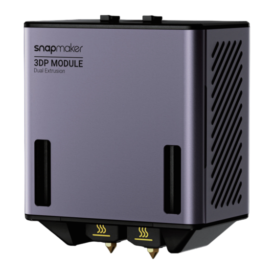
- Page 1 Dual Extrusion 3D Printing Module QUICK START GUIDE MAKE SOMETHING WONDERFUL...
- Page 2 CONTENTS Before You Start Machine Assembly 3D Printing Maintenance...
- Page 3 All the Snapmaker filaments are compatible with this product and have been tested for safety. If you use this product with third-party filaments, Snapmaker does not assume responsibility and expressly disclaims liability for any adverse effects from...
- Page 4 - Do not leave the product unattended while it is still powered on. written permission of Snapmaker. We reserve the right to modify or revise this - Always unplug the power cable from the electrical outlet before performing manual in our sole discretion at any time without notice.
- Page 5 Dual Nozzle: 310 mm × 325 mm × 290 mm Left Nozzle / Right Nozzle: 310 mm × 330 mm × 290 mm Snapmaker 2.0 A150, Snapmaker 2.0 A150DET, Snapmaker 2.0 A150 Bundle, Snapmaker 2.0 A250, Snapmaker 2.0 A350, Snapmaker 2.0 A250T, Snapmaker 2.0 A350T, Snapmaker 2.0 Compatible A250ENT, Snapmaker 2.0 A350ENT, Snapmaker 2.0 A250DET,...
- Page 6 Double End Studs M4×12 Screw Download the latest version of Snapmaker Luban from https://snapmaker. com/snapmaker-luban. If you have already installed Snapmaker Luban on your computer, ensure that its version is 4.5.0 or later. This guide takes version 4.5.0 as a demonstration.
- Page 7 In the chapter of Machine Assembly, to describe how to assemble the machine under the two scenarios of the machine without the Enclosure and with the Enclosure installed, this guide takes Snapmaker 2.0 A150 and A350T as a demonstration. While in the chapter of 3D Printing, all steps demonstrated on Snapmaker 2.0 A350T apply to all the other compatible machine models.
- Page 8 Machine Assembly 2.1 Scenario 1: Enclosure Not Installed on the Machine 2.1.1 A150 If the Enclosure is not installed on your machine, follow the corresponding steps below to install the Dual Extrusion Module and the Filament Holder(s) in Attach the Dual Extrusion Module to the slider on the X accordance with your machine models.
- Page 9 Machine Assembly Extend the Filament Holder Tube on the basis of the Connect the Dual Extrusion Module with the controller. original Filament Holder. Make sure the connector is in the right direction. Original Thumb Screw ×1 Filament Holder Tube ×1 Double End Studs ×1 Original Filament Holder Tube...
- Page 10 Machine Assembly 2.1.2 A250/A250T/F250/A350/A350T/F350 Attach the Dual Extrusion Module to the slider on the X Attach the two cable clips to the X axis and the Z axis. axis. Dual Extrusion M4×8 Screw ×4 Module ×1 Cable Clip ×1 M4×10 Screw ×1 Cable Clip ×1...
- Page 11 Machine Assembly Connect the Dual Extrusion Module with the controller, and Attach the new Filament Holder to the other Z axis. then lock the Toolhead Cable into place. M4×10 Screw ×1 New Filament Holder Tube ×1 Make sure the connector is in the right direction.
- Page 12 2.2.1 A150/A250/A250T/F250/A350/A350T/F350 2.2 Scenario 2: Enclosure Installed on the Machine This guide takes the Enclosure of Snapmaker A350/A350T/F350 as a demonstration to describe how to install the Filament Holder and the Filament Tube Holder. All steps demonstrated apply to the Enclosure of Snapmaker A150, A250/A250T/F250.
- Page 13 Machine Assembly Insert the Sliding Nut into the 48CA Beam on the left of the Attach the new Filament Holder to the Sliding Nut. Enclosure. Adjust the installation position of the Sliding Nut, in alignment with where the Snap Bushing is. Sliding Nut ×1 M4×10 Screw...
- Page 14 Machine Assembly Press both sides of the Snap Bushing inside the Enclosure, Mount the Filament Tube Holder and the Filament Tube and then gently push it out of the Side Panel. onto the Side Panel. Filment Tube Holder ×1 Filment Tube ×2 If you are using the A150 Enclosure, cut the Filament Tube as needed.
- Page 15 3D Printing 3D Printing Remove the tube fixture from the filament entry, insert the Filament Tube into the module, and finally attach the tube fixture back. Location of the Filament Tube Clips Before laser or CNC processes, you need to stick the provided tube clips to the illustrated position inside the Enclosure and press the Filament Tube into the clip.
- Page 16 Check. Before you start the calibration, we recommend that you read this section to learn about each process. : Download our firmware from https://support.snapmaker.com > insert the USB flash drive into the controller > turn on the machine > swipe left on the Touchscreen >...
- Page 17 3D Printing 3.3.1 Leveling & Z Offset Calibration Brief Introduction 1. Tap Start, and the machine will run the Heated Leveling in Auto Mode by The Dual Extrusion Module features a smart sensor that can be used to default. automatically level the build plate and adjust the distance between the two nozzles and the build plate.
- Page 18 3D Printing 2. Tap Got it to start heating. After the temperature of the Heated Bed reaches 3. Wait for the machine to finish Leveling, and then it will automatically enter the the target temperature, tap Start Leveling. Z Offset Calibration process. Do NOT touch the Heated Bed with bare hands while using the Every time after you have reassembled the module or machine, Heated Leveling mode.
- Page 19 3D Printing 4. After finishing the Z Offset Calibration, tap Next to enter the XY Offset Calibration process. How It Works The filament is fed into the module via the filament entry, passed by the extruder to the hot end, and extruded out of the nozzle after being heated. Our Dual Extrusion Module adopts the design of the dual-gear extruder, which features better extruding force, achieves stable and smooth loading 3.3.2 XY Offset Calibration...
- Page 20 3D Printing Load Filament Without the Enclosure Installed 3. When the heating completes, tap Load and then insert the black PLA filament into the left nozzle. Tap Stop Loading when the filament extrudes successfully. 1. Hang the filaments onto the Filament Holders in the order of "black filament on the left and white filament on the right", and cut the bending end of the filaments using the diagonal pliers.
- Page 21 3D Printing 4. Tap Next and repeat Step 3 to load the white Breakaway PLA filament into 5. Clean the nozzles using the tweezers, and tap Both Filament-loaded. the right nozzle. If no filaments are coming out of the nozzles, do not tap Both Filament-loaded until you repeat the steps above and the filaments extrude successfully.
- Page 22 3D Printing Load Filament With the Enclosure Installed 1. Hang the filaments onto the Filament Holders, and cut the bending end of the Make sure to load the black PLA filament into the left nozzle and filaments using the diagonal pliers. the white Breakaway PLA filament into the right nozzle, which is required to print the test model.
- Page 23 3D Printing 5. Tap Next and repeat Step 4 to load the white Breakaway PLA filament into How It Works: XY Offset Calibration the right nozzle. The machine will print a calibration model in the X and Y orientations, respectively. After you have selected the best pair of lines (where the top line is 6.
- Page 24 3D Printing 1. When the filament loading completes, the machine will automatically print 3. Slide to choose the best pair of lines. the calibration models. If the printing is unsuccessful, clean the Print Sheet. Now you can either tap Print Again, or return to Calibration and redo the Leveling and Z Offset Calibration.
- Page 25 3D Printing 1. Tap Start to start printing. After the printing completes, remove the print from 2. Follow the prompts on the Touchscreen to check the Z Offset Calibration the Print Sheet. results. If the printing is unsuccessful, clean the Print Sheet. Now you can either tap Print Again, or return to Calibration and redo the Leveling, Z Offset Calibration and XY Offset Calibration.
- Page 26 3D Printing 4. If all the offset calibrations are successful, tap Complete and now you can 3. Follow the prompts on the Touchscreen to check the XY Offset Calibration start printing. If not, the calibration failed will be marked with a red dot. Tap results.
- Page 27 Snapmaker Luban with your 3.4.1 Generate the G-code File machine: 1. Launch Snapmaker Luban, click Settings > Preferences in the menu bar to a. On the Home page of Snapmaker Luban, click to enter Workspace;...
- Page 28 3D Printing 4. Follow the Beginner's Guide to get familiar with the basic operations. During this process, Luban will automatically load the test model and generate the After the printing starts, you need to pay close attention to the G-code file. first layer adhesion to detect any problems in time to avoid wasting filaments.
- Page 29 3D Printing 3.4.3 Remove the Print Filament Runout Recovery & Power-Loss Recovery Your printer supports filament runout recovery and power-loss recovery, so Wait for the nozzles and the Heated Bed to cool down (temperatures displayed there is no need to worry about resuming printing anymore! When the filament on the Touchscreen).
- Page 30 Maintenance 4.1 Clean the Dust Screen Maintenance The dust in the air will adhere to its dust screen on both sides of the Dual Extrusion Module in daily use. If not removed in time, the accumulated dust may hinder heat dissipation and affect the working efficiency of the module. When At least once every two weeks.
- Page 31 Maintenance 4.2 Clean the Nozzle 3. After the nozzle is heated, scrape off the filament residue from the nozzle surface with the wire brush. During the 3D printing process, some of the extruded filament may stick to the nozzle surface. After the nozzle cools, these filament residues will solidify on its surface.
- Page 32 Maintenance 4.3 Clean the Extruder Gears 4. Clean the filament shavings from the extruder gears with the banister brush. Strong friction will be generated between the extruder gears and the filament during printing, due to which lots of small shavings will be ground away from the filament.
- Page 33 Original Instruction Y.3.B.A.0093-01 V1.0.0...
Need help?
Do you have a question about the Dual Extrusion 3D Printing Module and is the answer not in the manual?
Questions and answers