
Related Manuals for Woodhaven 7500


Summary of Contents for Woodhaven 7500
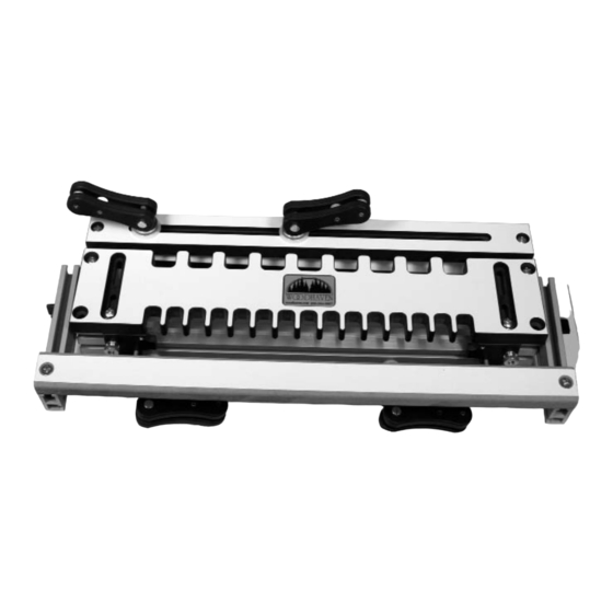
- Page 1 7500 Dovetail Jig Owners Manual PLEASE READ CAREFULLY! Portable mode set-up Stationary mode set-up Shown with optional 6104 Kamtite Clamps Tools needed for assembly: Phillips screwdriver 7/16" wrench...
- Page 2 7500H Hardware Before beginning, identify and verify that you have all the hardware shown List of additional parts not shown in hardware drawings - refer to photos in instructions: Qty Part# Description Qty Part# Description Qty PN Description NUT010A locknut 5760B oval nut 7500G MDF Base...
- Page 3 7500H Hardware Before beginning, identify and verify that you have all the hardware shown Qty Part# Description Qty Part# Description Qty Part# Description dovetail bit WN001 11/16" nylon washer 5780B 1-1/2" socket hd.bolt Qty Part# Qty Part# WB002 5520 Description Description Qty Part# Description...
- Page 4 ATTACH DOVETAIL TEMPLATE Attach the Dovetail Template (7500T) to the Side sup- Fig. 4 Oval Nuts ports and the Front support. Place one oval nut (B-5760B) into the top T-slot of both Side Supports. Place two oval nuts in the top T-slot of the Front Support, one on either side of the cutout area.
- Page 5 Fig. 12 7500A Front Support Fig. 11 Bolt installed from back Fig. 10 7500A Front Support Hdw. installed - ready for Clamp Bar ATTACH CLAMP BAR TO FRONT SUPPORT Insert two 3" hex bolts (G-HB060) into the lower T-slot of the Front Support thru the machined opening in the back of the Front Support.
- Page 6 CLAMP BAR STRIPS Fig. 16 Peel the paper backing off the Clamp Bar Strips (7500M) and install them on the inside face of the Clamp Bar and the Clamp Bar Fig. 17 support where shown. See fig. 20A. They help hold the horizontal stock tight against the underside of the dovetail template.
- Page 7 ROUTER SUPPORT - FOR STATIONARY USE ONLY Fig. 24 Insert one 3/4" hex bolt (C-HB020) into the lower T- slot of each Side Support. Install a Support Block (K- 7500RS) and a brass knob (S-5520) on each bolt. See fig. 7500F Support Arm 25.
- Page 8 INSTALL DOVETAIL BIT Install the dovetail bit (P-780) in your router. Set the Fig. 27 bit depth at 1-1/32". See fig. 27. This may need to be adjusted later after making a test cut. As an alternative to our 780 Dovetail Bit, you can use our 5030 - 5/8" Guide Bushing, 5040 Locknut and any 1/2"...
- Page 9 JOINT FIT Fig. 32 Moving Template forward The pins (also known as Moving Template back from from Stop increases amount dovetails) cut in the drawer side Initial Stop Setup Stop reduces amount drawer drawer side overhangs Template set flush should slide into the sockets (cut side overhangs drawer front.
- Page 10 STOCK SPECS This jig is designed for 3/8" to 1" thick stock. 1/2" stock is the most common thickness used for drawers. The stock used for the fronts & backs can be a different thick- ness then the stock used for the sides All stock should be flat and straight.
- Page 11 The rabbet in the drawer front should be at least 5/16" deep drawer, but is quicker and easier to make. to clear the dovetail bit. See fig. 37. ©Copyright WOODHAVEN INC. 8/27/04 (800) 344-6657 or WWW.WOODHAVEN.COM Minimum 5/16" 7/8" wide spacer...
- Page 12 Fig. 38 Drawer Back -Inside Face Cut 1/32" longer then desired finished length. Part marking suggestion: mark mating ends with same number so you know to do those parts as a pair Drawer Side - Drawer Side - Inside Face Inside Face Cut drawer bottom groove fig..
Need help?
Do you have a question about the 7500 and is the answer not in the manual?
Questions and answers