Advertisement
Quick Links
Parts List
Please identify and verify that you have all of the hardware
& parts shown prior to assembly. The parts described in this
box are identified in the instructions:
Part
Description
4002
1-7/8" Double Track . . . . . . . . . . . . . . . . 4
4004
4" Double Track . . . . . . . . . . . . . . . . . . . 2
4006
6" Double Track . . . . . . . . . . . . . . . . . . . 2
4009
9-1/4" Double Track . . . . . . . . . . . . . . . . 2
4024
24" Double Track . . . . . . . . . . . . . . . . . . 2
6000B
Crank Support . . . . . . . . . . . . . . . . . . . . 1
6000C
Crank Handle, 2 piece set . . . . . . . . . . 1
6000D
Phenolic Fence . . . . . . . . . . . . . . . . . . . . 2
6000F
Dust Channels, set of 2 . . . . . . . . . . . . 1
6000HD
Hold-All Kit . . . . . . . . . . . . . . . . . . . . . . . 1
6000N
Bit Insert . . . . . . . . . . . . . . . . . . . . . . . . . 2
6000S
Phenolic Sides, Pair . . . . . . . . . . . . . . . . 1
6000T
Phenolic Table . . . . . . . . . . . . . . . . . . . . 1
224
Guard . . . . . . . . . . . . . . . . . . . . . . . . . . . . 1
6000PA
Angle-Ease Router Plate . . . . . . . . . . . . 1
1470X
Angle-Ease . . . . . . . . . . . . . . . . . . . . . . . . 1
PLUS ONE of the Angle-Ease Motor Blocks below:
1470B
Angle-Ease 3 .5" motor block . . . . . . . . 1
1472B
Angle-Ease 4 .2" motor block . . . . . . . . 1
Part#
Description
Qty.
WS002
Washer
20
Part#
Description
Qty.
5760B
Oval Nut
36
Quantity
Part#
Description
Qty.
MF020
1-1/4" Screw
8
Part#
Description
Qty.
MF015
1" Screw
4
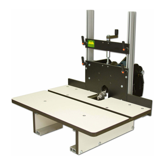
6002 & 6004
Horizontal
Router Table
Owners Manual
Please Read Carefully!
Part#
Description
Qty.
HB040
1-1/4" Bolt
16
Part#
Description
Qty.
5770B
1/2" Screw
4
Part#
Description
Qty.
5771B
3/4" Screw
4
Part#
Description
Qty.
5859
Ratchet Handle 4
Part#
Description
Qty.
MF010
3/4" Screw
Part#
Description
Qty.
6000G
Track Guide
4
Part#
Description
Qty.
5503
Thumb Screw
2
BEFORE BEGINNING
Identify and verify that you
have all the parts listed. Read
the instructions at least once,
familiarizing yourself with the
parts, before beginning. You'll
need a #3 Phillips screwdriver
and a 7/16" wrench for assembly.
6
Advertisement

Related Manuals for Woodhaven 6002


Summary of Contents for Woodhaven 6002
- Page 1 6002 & 6004 Horizontal Router Table Owners Manual Please Read Carefully! Parts List Please identify and verify that you have all of the hardware & parts shown prior to assembly. The parts described in this box are identified in the instructions:...
-
Page 2: Double Track
ATTACH PLATE & TRACKS The router plate (6000PA) has ribs on both short sides that guide the plate in the tracks. The router plate can be mounted in one of two ways: If the bit opening in the router plate is placed at the top, the router will tilt down and the bit will tilt up. If you place the bit opening in the router plate at the bottom, as shown in drawings, the router will tilt up and the bit will tilt down. Decide which way you want to tilt the router/bit. On two ratchet handles (5859), insert a washer (WS002) on the stud, insert the studs thru the top two corners of the router plate and start an oval nut (5760B - smooth side first) on the ends of the studs. Install four 1” screws (MF015) thru the four countersunk holes in the router plate and start a track guide (6000G - chamfered side first) on the ends of the screws. The hole gets tighter as you tighten the screw in the track guide, reducing any chance of vibration loosening the screw. Slide a 24” Double Track (4024) on the oval nut and two track guides on each short side of the router plate. Position the Double Tracks so the 1-1/2” wide smooth 5760B x2 sides are facing each other and the T-slot sides are facing out away from each other. 5859 x2 WS002 x2 The rib on each side of the router plate... - Page 3 ATTACH SIDES & TRACKS Install a washer (WS002) on twelve 1-1/4” bolts (HB040). Insert the bolts thru the holes shown in the pair of phenolic sides (6000S) and start an oval nut (5760B - smooth side first) on the ends of the bolts. The sides should look like mirror images of each other when done. Slide a 9-1/4” Double Track (4009) and a 6” Double Track (4006) onto the oval nuts located near the long edges of each side. Position the tracks even with the end and edges of each side and tighten the bolts. Lay the 24” Double Tracks/Router Plate on a flat surface and slide the two sides/oval nuts at the back of the sides on to the two tracks. Square the tracks to the sides, adjust the tracks flush to the bottom of the sides and tighten the four bolts. There is an extra set of mounting holes in the Phenolic Sides (6000S) which allow you to elevate the 9-1/4” Double Tracks (4009) & Table (6000T) 3/4”. This extra table height may be desirable depending on the how you have the Angle-Ease plate mounted. 5760B x12 HB040 x12 WS002 x12...
- Page 4 ATTACH DUST CHUTES Get the set of Dust Chutess (6000F) and insert two 3/4” flat head screws (MF010), thru the two holes in each Dust Chute, then start an oval nut (5760B - flat side first) on the ends of the screws. Attach a 1-7/8” Double Track (4002) to each oval nut and loosely tighten for now. Install a washer (WS002) on four 1-1/4” bolts (HB040). Insert the bolts thru the holes shown in the pair of phenolic sides (6000S) and start an oval nut (5760B - smooth side first) on the ends of the bolts. Slide the front Dust Chute without the cutout on to the inner most oval nuts on the sides and tighten the bolts, then loosen and retighten the screws holding the Dust Chute. Repeat for the rear Dust Chute with the cutout. 5760B x8 HB040 x4 MF010 x4 WS002 x4...
- Page 5 ATTACH TABLE & FENCE BRACKETS Install eight 1-1/4” flat head screws (MF020) thru the countersunk holes in the phenolic table (6000T) and start an oval nut (5760B - smooth side first) on the ends of the screws. The four screws/oval nuts in the main field of the table are used to attach the table to the 9-1/4” tracks. Slide the table/four oval nuts onto the tracks, position the table so its approximately 1/32” from the face of the router plate and tighten the screws. l i c 5771B x4 MF020 x4 5760B x8 From each side of the table, slide a 4” double track (4004) onto two oval nuts on the underside of the table so the T-slot in the edge of the track faces towards the edge of the phenolic table and hangs past it slightly. Center the track on the oval nuts and tighten the screws. Insert a 3/4” screw (5771B) thru the holes in the phenolic fences (6000D) and start an oval nut (5760B - smooth side first) on the ends of the screws. Slide the oval nuts/fences onto each 4” double track, position the end of the fence 1/32” from the edge of the...
-
Page 6: Screw
INSTALL CRANK HANDLE & ROUTER Get the crank handle (6000C). There 5760B x2 are two assemblies 5770B x4 to this part - one has a crank, nut, and mounting bracket, the other has a bolt and both and mounting bracket. Attach the bolt 5859 x2 assembly to the back WS002 x2 top of the router plate with two 1/2” screws (5770B) thru the two holes in its mounting bracket, but leave them loose for now. Install the crank assembly on the back of the crank support (6000B - the side with the machined ends) using two 1/2” screws (5770B) thru the two holes in its mounting... -
Page 7: Thumb Screw
ATTACH ANGLE-EASE, ROUTER & GUARD Assemble and mount the Angle-Ease (1470X) to the router plate following the instructions provided with it. After completing that, mount your router in the Angle-Ease. Insert the two thumb screws (5503) through the slots of the Guard (224) and into the threaded holes in the router plate (6000PA). MOUNT ZERO-CLEARANCE INSERT Mount a zero-clearance insert (6000N) in the recessed opening in the table using two 3/4” flat head screws (MF010). An extra insert is provided. 5503 x2 MF010 x2... - Page 8 Hex Bolt Knob . . . . . . . . . . . . . . . . . . .2 6000HD HOLD-ALL KIT: Insert the 1” hex bolts (HB030A) into the hex recess in the Verify that you have all the parts listed. hex bolt knob (5545). Install a washer (WS002) on each Unplug the router and remove the guard from the bolt. Insert the bolts through the slots in the Hold-Down router plate of the Horizontal Router Table. Featherboard (240B) and screw them in to the guard mounting holes in the router plate. The featherboard teeth should The 242 Miter Hold-In is designed to fit into the miter be pointing in the same direction the stock will be fed. slot in the Horizontal Router Table. Attach it to the table using the hardware and following the directions that came Insert the work in between the featherboards and with it. Make sure the direction of the featherboard teeth work surface. Apply pressure to the featherboards to point in the same direction that the stock is being fed. compress the fingers slightly against the work, then tighten the knobs. As the work passes each finger it will spring back and help prevent the work from kicking back. ©Copyright WOODHAVEN INC. 6/25/15 (800) 344-6657 or WWW.WOODHAVEN.COM...
Need help?
Do you have a question about the 6002 and is the answer not in the manual?
Questions and answers