Advertisement
Quick Links
Parts List:
Please identify and verify that you have all of the
hardware & parts listed and shown prior to assembly.
Part
Description
6012A
MDF Base . . . . . . . . . . . . . . . . . . . . . . . . . 1
6012B
Slide Plate . . . . . . . . . . . . . . . . . . . . . . . . 2
6012T
Fence . . . . . . . . . . . . . . . . . . . . . . . . . . . . . 1
4212
12" One Track . . . . . . . . . . . . . . . . . . . . . 2
4206
6" One Track . . . . . . . . . . . . . . . . . . . . . . 2
6305IC
Inboard Toggle Clamp . . . . . . . . . . . . . 2
Part#
Description
Qty.
MP375
3/8" Screw
4
Part#
Description
Qty.
MF006
5/8" screw
4
Part#
Description
Qty.
MF015
1" Screw
2
BEFORE BEGINNING
Identify and verify that you have all the parts listed.
Read the instructions at least once, familiarizing yourself
with the parts, before beginning assembly. You'll need a #3
Phillips screwdriver and a 7/16" wrench for assembly.
The Standard Mortise Table is designed to be used
with our 6000-6004 Horizontal Router Table.
Quantity
Part#
Description
Qty.
HB030
1" Bolt
4
Part#
Description
Qty.
HB050
1-1/2" Bolt
2
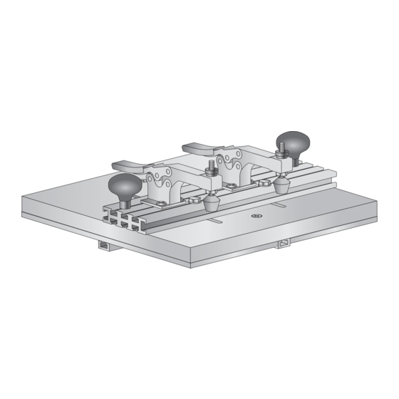
6012 Standard
Mortise Table
Owners Manual
Please Read Carefully!
Part#
Description
5765B
Offset Oval Nut 4
Part#
Description
5760B
Oval Nut
Part#
Description
Qty.
5590
Knob
2
Qty.
Part#
Description
NUT025
Square Nut
Qty.
Part#
Description
6
WS002
Washer
Part#
Description
BUSH004 5/8" Spacer
Part#
Description
5548
2" T-Knob
Qty.
2
Qty.
4
Qty.
2
Qty.
2
Advertisement

Related Manuals for Woodhaven 6012


Summary of Contents for Woodhaven 6012
- Page 1 6012 Standard Mortise Table Owners Manual Please Read Carefully! Parts List: Please identify and verify that you have all of the hardware & parts listed and shown prior to assembly. Part Description Quantity 6012A MDF Base . . . . . . . . . . . . . . . . . . . . . . . . . 1 6012B Slide Plate .
- Page 2 Insert a 5/8” screw (MF006 x4) thru the two 1/4” countersunk holes in each Slide Plate (6012B) and start an oval nut (5760B x4), smooth side first, on the end of each screw. Slide a 12” One Track (4212) on to the oval nuts, position it square and flush to the long edge of one Slide Plate and tighten the two screws. Slide the second Slide Plate onto the same One Track, lay the second 12” One Track between the two Slide Plates, butt them all together, tighten the screws on the 6012B second Slide Plate and MF006 remove the second One Track. 6012B 4212 4212 5760B There are two pairs mounting holes to select from in the MDF Base (6012A). The choice of which pair of holes to use will depend if the Standard Mortise Table will be used for end mortises (Fence 90º to router plate of the Horizontal Router Table) or edge mortises (Shown - Fence parallel to router plate MF015 of the Horizontal Router Table). Select the pair of holes desired (can be switched any time), insert a 1” screw (MF015 x2) thru the 1/4”...
- Page 3 F or parts less than 1-1/4” thick, attach the Toggle Clamps (in 6305IC bag) directly to the center T-slot of the Fence using the 3/8” screws (MP375 x2 per clamp) and offset oval nuts (5765B x2 per clamp). For parts 1-1/4” to 1-3/4” thick, elevate MP375 & the Toggle Clamps 5765B 1/2” above the Fence using hardware included in the Inboard Clamp Hardware (6305IC). I nsert two 1” bolts (HB030) in the rear T-slot in the Fence, then a 5/8” spacer (BUSH004) and handle (5590) on the end of each bolt. Position the handles in the bottom corners of the Fence and tighten. HB030 BUSH004 & 5590 I nsert a 1” bolt (HB030) thru the hole near each end of the miter slot in the Horizontal Router Table. Install a washer (WS002) and a 2” T-knob (5548) on each bolt on the underside of the table. Slide a 6” One Track (4206) onto the head of each bolt, position them where desired to control travel of the Mortise Table/length of the mortise and tighten the knobs.
- Page 4 USING THE MORTISE TABLE M ake sure the part and Mortise Table are not touching the bit, then turn on the router. Hold the handles of the Mortise Table and plunge the part/Mortise Table into the bit, feeding the Mortise Table from right to left as you face the bit. Keep downward pressure on the Mortise Table at all times. For best results when mortising, you should not cut deeper than the bit diameter in each pass. For example, a 1/4” bit should not cut deeper than 1/4” per pass. Since it may not be practical to adjust the bit depth that often, you may want to use the following method. Adjust the bit to the full cut depth desired and use spacers to limit the depth of cut of each pass. Using a 1/4” wide by 1” deep mortise as an example, cut a three 1/4” thick spacers 1” to 1-1/4” wide and 10” or more long. Place three spacers between the MDF base and the router plate to make the first 1/4” deep cut. Remove one 1/4” thick spacer for each cut that follows, until all spacers have been removed and you make the last cut at the full 1” cut depth. ©Copyright WOODHAVEN INC. 6/30/14 (800) 344-6657 or WWW.WOODHAVEN.COM Remove one 1/4” thick spacer for each cut that follows, until all spacers have been removed and you make the last cut at the full 1” cut depth.
Need help?
Do you have a question about the 6012 and is the answer not in the manual?
Questions and answers