Advertisement
Additional Hardware:
Identify and verify that you have all of the
hardware shown below prior to assembly.
Tools needed for assembly: #3 Phillips screwdriver
Parts listed are not shown in the hardware drawings
below. Refer to photos in the instructions:
Part Desc . . . . . . . . . . . . . . . . . . . . . . . . . . . Qty
5435A Fence . . . . . . . . . . . . . . . . . . . . . . . . . . . . . . . . . . . . . . . 2
5435B Base . . . . . . . . . . . . . . . . . . . . . . . . . . . . . . . . . . . . . . . . . 1
5435C Clamp Pad . . . . . . . . . . . . . . . . . . . . . . . . . . . . . . . . . . . 2
4206
6" One Track . . . . . . . . . . . . . . . . . . . . . . . . . . . . . . . . . 2
Part#
Description
Qty .
5760B
Oval Nut
4
Part#
Description
Qty .
MF020
1-1/4" screw
2
Part#
Description
Qty .
5521
1/4" Knob
4
Part#
Description
Qty .
5525
5/16" Knob
2
Part#
Description
Qty .
5775B
5/8" Screw
4
Part#
Description
Qty .
BUSH004 5/8" Spacer
2
Part#
Description
Qty .
BUSH050 3/8" Spacer
4
Part#
Description
Qty .
5540
Knob
2
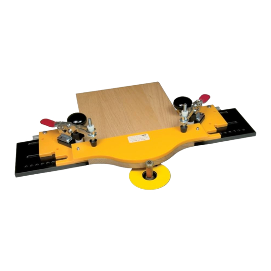
5435 Frame &
Panel Master
Owners Manual
U.S. Patent #5,960,843
Please Read Carefully!
BEFORE BEGINNING
Identify and verify that you have all the parts listed. The
Frame & Panel Master was designed to be used with Woodhaven
Standard Door Templates and router bits only. It will hold parts
between 5" and 20" long/wide and up to 7/8" thick. If you desire
to do this type of work on a shaper with shaper cutters, you'll need
our HD Frame Master, HD Panel Master and HD Templates. Read
the instructions carefully at least once before beginning.
Part#
Description
Spring3
Spring
Part#
Description
HB050
1-1/2" Bolt
Part#
Description
HB060
3" Bolt
Part#
Description
MP375
3/8" Screw
Shown with optional
toggle clamps
Qty .
2
Part#
Description
5548
2" T-Knob
Qty .
4
Part#
Description
Qty .
5590
Knob
2
Qty .
Part#
Description
4
HB055
2" Bolt
Qty .
2
Qty .
2
Qty .
2
Advertisement
Table of Contents

Related Manuals for Woodhaven 5435


Summary of Contents for Woodhaven 5435
- Page 1 5435 Frame & Panel Master Owners Manual U.S. Patent #5,960,843 Please Read Carefully! Additional Hardware: Identify and verify that you have all of the hardware shown below prior to assembly. Tools needed for assembly: #3 Phillips screwdriver Parts listed are not shown in the hardware drawings Shown with optional below.
- Page 2 ASSEMBLY Insert two 5/8" screws (5775B) thru the holes indicated in & each fence and start an oval nut (5760B), flat side first, on the end of each screw. Slide a 6" one track (4206) on the oval nuts, centered on the fences (this position can be adjusted later if desired) and tighten the screws. Slot C 5775B x2 Slot B Slot A 5760 x2 Attach the fences to the base (5435B), but first determine whether you'll be cutting panels or rails: RAIL WORK: the fences should be placed 5595 x2 with their notched edges facing each other. - See Right PANEL WORK: the fences should be placed BUSH004 x2 HB050 x2 with their straight edges facing each other. - See Above Install two 1-1/2'' bolts (HB050), one on each side, thru the bottom of the base (5435B) Select the Standard into slot "C". Install a fence on each bolt, Door Template you wish followed by a 5/8'' spacer (BUSH004) and a to use. Note: You will not use knob (5590). The 6" One track on each fence the indexing fences or hardware should be snug against the edge of the base...
- Page 3 Insert a 3" bolt (HB060) thru the bottom of the base in slot "B", one on each side, and thru the hole 5548 x2 in each fence nearest the inside edge (closest to the work piece). 5435C BUSH050 x4 Screw a 1/4" knob (5521) on each 1-1/4" screw (MF020) and install the screw/knob in the threaded hole in the clamp pads (5435C). Adjust the height of the screw head to match the thickness of the wood you're machining and tighten the HB060 x2 knob. Install the clamp pads on the 3" bolts, followed by two 3/8" 5521 x2 spacers (BUSH050) and knob (5548). MF020 x2 CUTTING RAILS Place the rail on the base and slide the fences in against each end of the rail so it's seated between the notches in the fences. Place the template on the 1-1/2" bolts/springs. a i n &...
- Page 4 Re-install the rail and clamp the template/rail to the base using the knobs on the clamp pads. t i o r e c Caution! The knobs are large and easy to tighten, but overtightening may cause damage to the jig! Hold the jig by the handles and machine the rail to shape using a flush trimming bit.
- Page 5 Remove the machined rail and install another. If you have a second router setup and your bit will reach high enough, you can go directly to machining the pattern (for cutters with a 1/2" deep profile max) without having to remove the rail between operations. For safety, at least 1/8" of the bearing should ride on the template, which also acts as a starting pin and provides the best control of the part. Depending on part thickness and bit design, this may require an additional spacer between the bearing and the cutter. You can also use a router fence, set back to accommodate the narrowest section of the rail, to help vacuum away cutting debris.
- Page 6 CUTTING PANELS Using the center mark on the back edge of the template Place the panel on the base and slide the fences up as a guide, adjust the fences/panel to center the panel on the against each side of the panel so it's between the straight edges template. Using the template as a pattern, draw a line on the of the fences. Place the template on the 1-1/2" bolts/springs. panel. Remove the panel and rough saw it to shape, staying approximately 1/8" away from the finished line.
- Page 7 Re-install the panel and clamp the template/ panel to the base using the knobs on top of the clamp pads. The knobs are large and easy to tighten, but overtightening may cause damage to the jig! Hold the jig by the handles and machine the panel to shape using a flush trimming bit. For extra Remove the machined panel and safety and dust install another. If you have a second router control, use a router setup and your bit will reach high enough, you fence for additional can go directly from shaping the panel with a support. Adjust the flush trim bit to machining the raised panel fence position so that the profile without removing the part between tallest part of the panel is operations. You'll need to slide the panel touching the fence, which forward so it sticks out past the acts like a starting pin and can template at least 1-5/8" to help vacuum away cutting debris. prevent the raised panel bit from cutting into the base.
- Page 8 OPTIONAL TOGGLE CLAMPS Attach each toggle clamp to the clamp pad using the 3/8" The optional toggle clamps (Woodhaven PN 6305 x2 - screws (MP375, 2 per clamp). Attach the clamp pads/toggle order separetly) attach to the 5435C Clamp Pads and replace clamps to the Frame & Panel Master using a 2" bolt (HB055 the standard knobs for faster part clamping. We include the - in place of the 3" bolt), a 3/8" spacer (BUSH050) and knob (5540). Replace the hex nut on the top of the toggle clamps additional hardware for attaching the toggle clamps with the 5435 Frame & Panel Master hardware. Remove the knobs, clamping spindle with a 5/16" knob (5525). spacers, clamp pads and 3" bolts from the Frame & Panel Master and the 1-1/4" screw and knob from each clamp pad. " e r h 5525 x2 6305 x2 Do not allow...
Need help?
Do you have a question about the 5435 and is the answer not in the manual?
Questions and answers