Table of Contents
Advertisement
Quick Links
7902 Dado Jig
Hardware List:
Identify and verify that you have all of the
hardware shown below prior to assembly.
Please read the instructions at least once,
familiarizing yourself with the parts
before beginning. You'll need to supply a
#2 Phillips screwdriver for assembly.
Part#
Description
Qty.
5760B
Oval Nut
42
Part#
Description
Qty.
BUSH002 1/4" Spacer
14
Part#
Description
Qty.
5540
Knob
6
Part# Description
Qty.
MF035 10-24 x 1/2" Screw 2
Part# Description
Qty.
MB020 1/4-20 x 1/2" Screw 36
Part#
Description
Qty.
HB030
1" Bolt
6
Part#
Description
Qty.
MF015
1" Screw
4
Part# Description
Qty.
5785 5/32" Allen Wrench 1
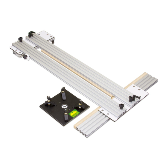
7902
Dado Jig
Owners Manual
Please Read Carefully!
7902 Parts List:
Parts listed below are shown in photos in the instructions:
Part
Description
4412
12" Ultra Track . . . . . . . . . . . . . . . . . . . . 1
4424
24" Ultra Track . . . . . . . . . . . . . . . . . . . . 1
4436
36" Ultra Track . . . . . . . . . . . . . . . . . . . . 1
7900T
36" Ultra Track with 2 holes . . . . . . . . 1
7900A
1/4" MDF Fence . . . . . . . . . . . . . . . . . . . 2
7900B
3/4" Edge Fence . . . . . . . . . . . . . . . . . . . 1
7900C
2 pc . Bracket Set . . . . . . . . . . . . . . . . . . . 1
7900E
Work Stop . . . . . . . . . . . . . . . . . . . . . . . . 2
7900G
Plate Guide . . . . . . . . . . . . . . . . . . . . . . . 1
7900P
Router Plate . . . . . . . . . . . . . . . . . . . . . . . 1
4973
Router Plate Hardware . . . . . . . . . . . . . 1
Part# Description
Qty.
5864 1-5/8" Ratchet Knob 2
Quantity
Advertisement
Table of Contents

Related Manuals for Woodhaven 7902


Summary of Contents for Woodhaven 7902
- Page 1 7902 Dado Jig Owners Manual Please Read Carefully! 7902 Dado Jig Hardware List: Identify and verify that you have all of the hardware shown below prior to assembly. Please read the instructions at least once, familiarizing yourself with the parts before beginning.
- Page 2 Thru Hole ATTACH MDF SUB-FENCES Identify the 36” Ultra Track (7900T) with a hole in the center slot near either end. This is the Adjustable Track and should be placed on the right hand side. Attach an MDF Sub-fence (7900A) to each 36” Ultra Track (4436 & 7900T). Insert a 1/2” screw (MB020) through the holes indicated on each Sub-fence and start an oval nut (5760B - flat side first) on each screw. Attach the Sub-fences to the Ultra Tracks as shown, with the oval nuts captured in a T-slot closest to the long edge of the tracks. Roughly center the Sub- 7900A x2 fences on the length of the track and snug the screws using the Allen Wrench (5785). Set the Adjustable Track aside for now. MB020 x4 5760B x4 Thru Hole 7900T - Adjustable Track 4436 - Stationary Track ATTACH BRACKETS Attach the Brackets (7900C - 2 pc.
- Page 3 ATTACH BACK & FRONT FENCES Install 1/2” screws (MB020) through the 8 countersunk holes in each Track Bracket (reposition the Adjustable Fence as necessary) and start an oval nut (5760B - flat side first) on each end. Install the 12” Back Fence (4412) and 24” Front Fence (4424) Ultra Tracks to the Brackets as shown by capturing the oval nuts in the T-slots in the track faces and sliding them into place. Center the 12” Back Fence end-to end on the Bracket. Keep the inner long edge of the Ultra Track flush with the long edge of 12” Back the Bracket and tighten the screws using the Allen Wrench (5785). Locate the end of the 24” Front Fence 6-1/2” from the end of Fence the Bracket near the Stationary Fence. Align the inner long edge of the Front Fence flush with the long inner edge of the Bracket and tighten the screws using the Allen Wrench (5785). MB020 x16 24” 5760B x16 Front Fence 6.5” ATTACH ROUTER PLATE STOPS Attach the Router Plate Stops by sliding the head of two 1” hex bolts (HB030) into the innermost T-slot of each 36” Ultra Track. Place two 1/4” bushings (BUSH002)
- Page 4 ATTACH PLATE GUIDE & ROUTER TO PLATE Attach the Plate Guide (7900G) to the Router Plate (7900P) using the 1/2” screws (MF035) and a Phillips screwdriver (not provided). Follow the directions 4973 in the 4973 Plate Hardware and attach your router to the Router Plate (7900P). Any type of router can be used but, to cut stopped dadoes (dadoes that don’t exit the edge(s) of the workpiece), you’ll need to use a plunge router. An optional drill style Router Plate (PN 7900PD) is available for semi-permanent mounting of your router, but it requires drilling mounting holes in the Router Plate. 7900P 7900G MF035 x2 SIZE 1/4” FENCES Loosen the 1/4” MDF Fences, re-position them so their front ends are slightly overlapping the front of the Edge Fence and tighten the screws. SELECT ROUTER BIT - IMPORTANT!!! For best results we recommend our 13700 1/2”...
- Page 5 SIZE 1/4” FENCES - CONT Temporailary remove the Edge Fence. Place the Router/Router Plate on the Tracks with the Plate Guide between the 36” Ultra Tracks. Adjust the front and back Stops so the router bit won’t strike the Front or Back Fences. Clamp the Dado Jig to a workbench using clamps (not provided). Temporarily place some scraps of 3/4” thick material under the center portion of the Stationary & Adjustable Tracks/1/4” Fences to support them as you use the router to size the 1/4” Fences. Re-install the Edge Fence once completed. SIZE 1/4” FENCES - CONT 1. Place the Router/Router Plate on the Dado Jig against the back Router Plate Stops (make sure bit is not touching the 1/4” MDF Fence). 2. With the Plate Guide between the Stationary & Adjustable Ultra Tracks, turn the router on and, while holding the edge of the Plate Guide against the inside edge of the Adjustable Track, pull the router forward along the Adjustable Track. 3. When you contact the front Router Plate Stops, slide the router to the left so the Plate Guide is against the Stationary Track. 4. While holding the edge of the Plate Guide against the inside edge of the Stationary Track, push the router rearward along the Stationary Track to the back Router Plate Stops. The 1/4” MDF fences are now sized to your router bit and you are now ready to cut dadoes with the Dado Jig.
- Page 6 SETUP FOR DADO WIDTH Workpiece sets dado Clamp, or bolt, the Front & Back Fences of the Dado width by indexing Jig to the workbench. Always check that the Front Fence is between 1/4” Fences square to the Stationary Track before beginning. Select the setup workpiece you want to cut the dado for. Loosen the Adjustable Track and place the setup workpiece on edge vertically between the sized 1/4” MDF Fences. Position the Adjustable Track so the workpiece is sandwiched snugly between the sized 1/4” MDF Fences, tighten the two knobs on the Adjustable Fence and remove the setup workpiece. Butt the two Work Stops against the back edge of the workpiece to be dadoed and tighten the knobs. These hold the workpiece against the Edge Fence. Clamp the workpiece to the workbench, or clamp stops to the workbench on either side of the workpiece, to hold it’s position while dadoing.
- Page 7 DADO JIG OPERATION 1. Place the Router/Router Plate on the Dado Jig against the back Router Plate Stops (make sure the bit doesn’t touch the workpiece), with the Plate Guide between the Stationary & Adjustable Ultra Tracks. 2. Turn the router on and, hold the edge of the Plate Guide against the edge of the Adjustable Track as you pull the router forward. 3. When you contact the front Router Plate Stop, slide the router to the left so the Plate Guide is now held against the Stationary Track. 4. Push the router rearward to the back Router Plate Stop.
- Page 8 DADO JIG STOP ACCESSORIES The Front Track of the Dado Jig can be extended on one or both ends. The Extension can be ordered as a 24” inch Extension (7924 shown) or a 48” Extension (7948). Both Extensions include a Track Connector (4536). The Extension allows you to attach Work Stops to the extra length of track to make cutting multiple dadoes on same size workpieces easier. The Extension (7924 or 7948) does not include any Flip Stops, (789S) which can be ordered separately. An accessory to the Flip Stop is the Micro Adjuster (4523). It attaches directly to the Flip Stop and allows up to 5/8" of fine adjustment. ©Copyright WOODHAVEN INC. 5/21/15 (800) 344-6657 or WWW.WOODHAVEN.COM 7924 24” Fence Extension 789S Flip Stop 789S Flip Stop with 4523 Micro Adjuster 789S Flip Stop...
Need help?
Do you have a question about the 7902 and is the answer not in the manual?
Questions and answers