Advertisement
Table of Contents
Parts List:
Part
Description
8615B
35mm Cup Routing Plate . . . . . . . . . . . 1
8615A
Mounting Plate . . . . . . . . . . . . . . . . . . . . 1
8615C
Stop . . . . . . . . . . . . . . . . . . . . . . . . . . . . . . 1
4212
12" One Track . . . . . . . . . . . . . . . . . . . . . 1
6305B
Clamp Riser Pad . . . . . . . . . . . . . . . . . . . 1
6305
Toggle Clamp . . . . . . . . . . . . . . . . . . . . . 1
Part#
Description
Qty.
HB030
1" Bolt
1
Part#
Description
Qty.
5771B
3/4" Screw
2
Part#
Description
Qty.
5540
Knob
1
Quantity
Part#
Description
Qty.
WB002
Washer
3
Part#
Description
Qty.
5765B
Offset Oval Nut 4
Part#
Description
Qty.
5770B
1/2" Screw
2
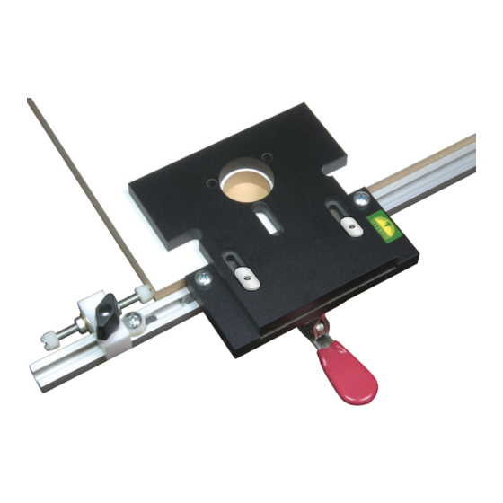
8615
Hinge Routing Jig
Please Read Carefully!
Part#
Description
BUSH002 1/4" Spacer
Part#
Description
BUSH001 1/8" Spacer
Part#
Description
5760B
Oval Nut
Qty.
Part#
Description
2
5772B
1" Screw
Qty.
Part#
Description
2
NUT250 Cap Nut
Qty.
Part#
Description
2
SD430
3" Stud
Part#
Description
NUT015 Hex Nut
Qty.
4
Qty.
2
Qty.
1
Qty.
2
Advertisement
Table of Contents

Related Manuals for Woodhaven 8615


Summary of Contents for Woodhaven 8615
- Page 1 8615 Hinge Routing Jig Please Read Carefully! Parts List: Part Description Quantity 8615B 35mm Cup Routing Plate . . . . . . . . . . . 1 8615A Mounting Plate . . . . . . . . . . . . . . . . . . . . 1 8615C Stop .
- Page 2 BEFORE BEGINNING Identify and verify that you have all the parts listed. Read the instructions at least once, familiarizing yourself with the parts before beginning. You'll 8615A need a #3 Phillips screwdriver for assembly. 5771B ASSEMBLY Attach the 12" One Track (4212) to the Mounting Plate (8615A) using two 3/4" screws (5771B) and two Offset Oval Nuts (5765B). Set the assembly on edge so the edge of the One Track and the edge of the Mounting Plate are even with each other, then center the One Track on the Mounting Plate and tighten the screws. See fig. 1 Insert two 1" Screws (5772B) thru the front mounting holes in the Toggle Clamp (6305), insert the 4412 non-threaded holes in the Clamp Pad (6305B) over the ends of the screws, then tighten the screws in the two threaded holes in the Mounting Plate. See fig. 2 5765B Set the 35mm Cup Routing Plate (8615B), with its recessed slots facing up, in the recessed area on the Mounting Plate. Set an Oval Nut (5760B - raised side up) in each slotted recess in the Cup Routing Plate. Install a 1/8" Spacer 5772B (BUSH001) on each of two 1" Screws (5772B) and insert the screws thru the holes in the Mounting Plate on either side of the Toggle Clamp, in to the oval nuts and tighten. See fig. 3 6305 Install a 1/4" Spacer (BUSH002) on two of the 1/2"...
- Page 3 Insert the 3" Stud (SD430) thru the hole in the Stop (8515C), install a washer (WB002) and Hex Nut (NUT015) on each end of the Stud. Center the Stud in the Stop and tighten the nuts. Install a Cap Nut (NUT250) on each end of the Stud. See fig. 5. Insert a 1" Bolt (HB030) thru the hole in the notch of the Stop. Install a Washer (WB002) and Knob (5540) on the end of the bolt. Slide the Stop in the One Track and tighten the Knob. See fig. 5 & 6 USING THE JIG The inside edge of the slot (near the center) in the Cup Routing Plate represents the center line of the jig and can be used to reference the jig to an index mark on the work. See fig. 3 Measure from the Cap Nut on the Stop to the center of the Cup Routing Plate and adjust the Stop to the distance needed (up to 4-1/4" or 108mm max.). Use the Screw/1/4" Spacer between the Mounting Plate and the Stop as a stop for the Stop. By adjusting this stop on each side of the jig, you can move the Stop from one side of the jig to the other when switching between right and left or up and down. Loosen the two screws fastening the Cup Routing Plate to the Mounting Plate. Measure between the edge of the Mounting Plate and the inside edge of the Cup Routing Plate to set the hinge backset (up to 23mm max.), then tighten the screws. See fig. 7 Continue on back page.
- Page 4 Install the router bit (8505, 3/4" cut length, 1/2" diameter with a 5/8" bearing and a 1/4" shank) or a 5/8" bushing and 1/2" router bit, in your plunge router. If using the 8505 Hinge Bit, make sure the bearing rides firmly on the edge of the jig before attempting any cuts. Set the cutting depth of the bit, taking into account the thickness of the jig. Plunge the router bit slowly into the approximate center of the hinge cup opening in the Cup Routing Plate, moving in a small clockwise circle as you plunge to cut a relief opening. Move towards an edge of the hinge cup opening, then move clockwise, following the edge of the hinge cup opening until the hinge cup has been cut. See fig. 9 Before moving the jig, use a 1/4" Marking Punch (8600) to mark the two hinge mounting holes on either side of the hinge cup for later drilling, or use a Self-Centering bit (6505 or 6507) to drill the two screw pilot holes for the hinge cup. See fig. 9 ©Copyright WOODHAVEN INC. 1/7/15 (800) 344-6657 or WWW.WOODHAVEN.COM...
Need help?
Do you have a question about the 8615 and is the answer not in the manual?
Questions and answers