Table of Contents
Advertisement
Quick Links
Advertisement
Table of Contents

Related Manuals for Phenix Technologies PM15-4A


Summary of Contents for Phenix Technologies PM15-4A
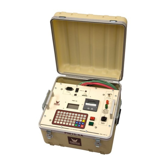
- Page 1 OPERATIONS AND APPLICATIONS MANUAL MODEL NUMBER PM15-4A 15 kV DC HIGH POTENTIAL TESTER WITH MEGOHMMETER Version 2.3 Phenix Technologies, Inc 75 Speicher Drive Accident, MD 21520 USA Phone 1 (301) 746-8118 Fax 1 (301) 895-5570 info@phenixtech.com copyright © Phenix Technologies...
-
Page 2: Table Of Contents
TABLE OF CONTENTS Section Number DANGER PRODUCT INFORMATION -SAFETY AND CAUTION NOTES -DESCRIPTION -PRODUCT INFORMATION -SPECIFICATIONS CONTROLS AND CONNECTIONS -FRONT PANEL CONTROLS AND METERS -INPUT/OUTPUT CONNECTIONS SET UP INSTRUCTIONS -INITIAL CHARGING -SETUP -TEST LEAD CONNECTIONS -SPECIMEN SET UP CAUTION -NOTES ON THE USE OF GUARD AND GROUND OPERATION INSTRUCTIONS -TEST METHODS -SAVING AND PRINTING... - Page 3 DO NOT operate damaged equipment. Remove power, and do not use the equipment until safe operation can be verified by service-trained personnel. Phenix Technologies, Inc. assumes no liability for unsafe or improper use of test equipment.
-
Page 4: Product Information
This unit should only be operated by someone familiar with high voltage testing and safety procedures. DESCRIPTION The PM15-4A unit is capable of producing regulated voltages as high as 15 kV DC into a variety of insulated electrical apparatus. The unit will measure leakage current flow through (or insulation resistance levels of) the ground insulation of the test sample. -
Page 5: Specifications
SPECIFICATIONS Description: DC High Potential Tester with Megohmmeter Primary Application: Dielectric withstand testing and I.R. measurement of motors, cables, and transformers. Input: 100-240 Volts AC, 47-63 Hz, single phase, 1.4 Amp Output: Regulated 100V-15 kV (negative output) DC, Positive Ground (± 2% of set point), 0-4mA Duty Cycle: Continuous output duty cycle, see Guidelines for Internal Discharge Circuit Below Internal Discharge Circuit Guidelines for Capacitive Loads (@ Max Output Voltage):... -
Page 6: Controls And Connections
2. CONTROLS AND CONNECTIONS Please refer to Figure 2.1 for identification of front panel components and their function. FIGURE 2.1: FRONT PANEL LAYOUT 1. AC Input: The provided AC input cable plugs in here to provide AC power to the unit. All fuses are internal to the unit and should not need replacement under normal conditions. - Page 7 6. Ground Terminal: This terminal is to be connected to the facility ground (black cable provided). Leakage current or insulation resistance values associated with this binding post terminal may be either measured by the “DC Microammeter” or bypassed around the “DC Microammeter” depending on the state of the Guard Mode.
-
Page 8: Setup Instructions
3. SETUP INSTRUCTIONS INITIAL CHARGING Before using the PM15-4A for the first time, perform an initial charging of the batteries as follows: 1. Make sure the main power switch is in the off position. 2. Plug in the supplied AC power cord and connect to the appropriate AC Power Source. -
Page 9: Specimen Setup Caution
PM15-4A. This effect is greatest at the maximum resistance values that the PM15-4A is capable of measuring, as well as timed tests. It is strongly recommended that a stable test set up is ensured... -
Page 10: Notes On The Use Of Guard And Ground
NOTES ON THE USE OF GUARD AND GROUND NORMAL MODE CONFIGURATION In this configuration the Return and Ground are connected together with a relay internal to the Test Set. Both stray leakage to earth ground and leakage through the Test Specimen are indicated on the current meter. - Page 11 NOTES ON THE USE OF GUARD AND GROUND GUARD MODE CONFIGURATION In this configuration Ground current is bypassed with a relay internal to the Test Set. Any current associated with the Return is indicated on the current meter. Any current associated with the Ground bypasses the current meter.
-
Page 12: Operation Instructions
From the Main Menu (Figure 2), there are 7 options displayed. The first 5 options are the different tests that the PM15-4A is capable of running. The last two functions are system tools to monitor the battery power and calibrate the unit itself. Simply press the number corresponding to the menu choice using the keypad to... -
Page 13: Test Methods
(40°C or 68°F). The PM15-4A has the capability to perform this calculation automatically by entering the test object temperature. The built in printer function allows the operator to document the... - Page 14 This status message will appear at the HV Waiting Screen if an open Security Circuit is detected regardless of what operation mode the PM15-4A is set to (Normal or Guard). If this message is seen, check the security circuit for loose connections or replace the SX1 plug onto the front panel to close the security circuit.
- Page 15 HV OFF button or the STOP key. The PM15-4A is also capable of Intra-Test Printing. During the I.R. test; the operator can print during a test at any time without waiting for the test to be completed for a real time print out of the data at a given moment.
- Page 16 Figure 11: Insulation Resistance Test Results Sample Printout Figure 11 shows a sample printout of the results of an Insulation Resistance Test. This printout reflects I.R. results of a one-minute duration test with output voltage of 8kV under Guard Mode operation.
- Page 17 4.1.2 Polarization Index Test FIGURE 12: Polarization Index Test ID Screen Enter an alphanumeric test identification (or leave blank) and press enter. When testing objects with large capacitance, it may take a considerable amount of time for the charging current to approach zero. Therefore it also may take considerable time before the IR test returns a true resistance reading.
- Page 18 This status message will appear at the HV Waiting Screen if an open Security Circuit is detected regardless of what operation mode the PM15-4A is set to (Normal or Guard). If this message is seen, check the security circuit for loose connections or replace the SX1 plug onto the front panel to close the security circuit.
- Page 19 Either printing or saving to the SD Card will give the operator results for every minute in addition to the final PI reading. The PM15-4A will discharge the test object upon test completion. Depending on the size of load capacitance, dangerous voltages may be present at the end of the lead for a few moments. Always ground any high voltage leads before removing leads from test object.
- Page 20 Figure 20: Polarization Index Test Results Sample Printout Figure 20 shows a sample printout the results of a Polarization Index Test. This printout reflects the P.I. results of a ten-minute test with output voltage of 8kV under Guard Mode operation.
- Page 21 4-10 4.1.3 Capacitance Test FIGURE 21: CAPACITANCE TEST ID Screen Enter an alphanumeric test identification (or leave blank) and press enter. FIGURE 22: Capacitance Setup Screen At the Capacitance Setup Screen (Figure 22), enter the maximum voltage to be applied in volts (5000V MAX).
- Page 22 This status message will appear at the HV Waiting Screen if an open Security Circuit is detected regardless of what operation mode the PM15-4A is set to (Normal or Guard). If this message is seen, check the security circuit for loose connections or replace the SX1 plug onto the front panel to close the security circuit.
- Page 23 Due to the variability of capacitive values that a test object may have, there will be an estimated wait time displayed in seconds in which the capacitor must be charged up by the PM15-4A in order to take the capacitance measurement.
- Page 24 Capacitance Test, and after applying a discharge stick as prescribed earlier. The operator is given the choice to save or print the final test data. The PM15-4A will discharge the test object upon test completion if the capacitive load is small enough to use the internal discharge circuit. Depending on the size of load capacitance, dangerous voltages may be present at the end of the lead for a few moments.
- Page 25 4-14 Figure 30: Capacitance Measurement Test Results Sample Printout Figure 30 shows a sample printout of a Capacitance Measurement Test. This printout reflects the results of a Capacitance Measurement Test with 500V output under Guard Mode operation.
- Page 26 4-15 4.1.4 Uniform Step Test FIGURE 31: Step Test I.D. Screen Enter an alphanumeric test identification (or leave blank) and press enter. The step test is used to establish trend curves. During the step test, the voltage is raised in discrete steps to a final level.
- Page 27 This status message will appear at the HV Waiting Screen if an open Security Circuit is detected regardless of what operation mode the PM15-4A is set to (Normal or Guard). If this message is seen, check the security circuit for loose connections or replace the SX1 plug onto the front panel to close the security circuit.
- Page 28 The operator is given the choice to save or print the final test data. The PM15-4A will discharge the test object upon test completion. WARNING; Depending on the size of load capacitance, dangerous voltages may be present at the end of the lead for a few moments.
- Page 29 4-18 Figure 39: Uniform Voltage Step Results Test Sample Printout Figure 39 shows a sample printout of a Uniform Voltage Step Test. This printout reflects the results of a Step Test of 5-minute duration, 15kV max output voltage, and 20 steps of voltage at a uniform 15-second duration each.
- Page 30 4-19 4.1.5 Dielectric Absorption Ratio (D.A.R. Test) Figure 40: Dielectric Absorption Ratio Test I.D. Screen Enter an alphanumeric test identification (or leave blank) and press enter. In good insulation systems, it is expected that the insulation resistance increases as the time dependant charging currents approach zero.
- Page 31 In this screen, the display reads that the PM15-4A is in Normal Mode. Pressing G on the keypad toggles between Normal Mode and Guard Mode Configuration (See Figure 44).
- Page 32 This status message will appear at the HV Waiting Screen if an open Security Circuit is detected regardless of what operation mode the PM15-4A is set to (Normal or Guard). If this message is seen, check the security circuit for loose connections or replace the SX1 plug onto the front panel to close the security circuit.
- Page 33 4-22 Figure 48: Dielectric Absorption Ratio Test Results Sample Printout Figure 48 shows a sample printout of a Dielectric Absorption Ratio Test. This printout reflects the results of a D.A.R. test with one-minute duration at 8kV output.
-
Page 34: Saving And Printing
Windows based data acquisition software is currently under development by Phenix Technologies for the PM15-4A. End users are free to develop their own front-end interface in conjunction with the data stream from the USB port to record and analyze results. -
Page 35: System Tools
4-24 4.3 SYSTEM TOOLS The PM15-4A has several pre-programmed system tools for operator use. The available items are listed on the System Setup screen, accessible through the Main Menu. Select the number on the keypad which corresponds with the available options to proceed. - Page 36 4-25 FIGURE 52: Date Setup Screen At the Date Setup Screen, users may enter the date in day, month, and year. “T” is used to toggle the date format to swap the position of the day with respect to the month and vice versa. FIGURE 53: System Information Screen At the System Information Screen, information about your specific unit is displayed including version number of the firmware, manufacturing date, total number of tests performed to date, total hours of operation of the...
- Page 37 It is recommended that only a Phenix Technologies Service Technician with approved standards calibrate this unit. Please contact the Phenix Technologies Service Department to request a factory calibration.
-
Page 38: Care And Maintainance
5. CARE AND MAINTAINANCE 5.1 NI-MH BATTERY MAINTAINANCE NI-MH batteries have a high self-discharge rate. It is therefore recommended to complete a full charge cycle at least once a week. If the batteries become discharged to the point the unit will no longer turn on under battery power, complete a full recharge cycle by plugging the unit in and leaving it plugged in for 3 hours. - Page 39 5.3.2 Status LED The printer incorporates a LED indicator to report its condition. If there is a fault, the LED will flash in sequence. The fault can be identified by counting the number of flashes. After extensive printing the print head temperature may rise to an unusable level. The Status LED will report when this occurs, and printing will be suspended until the head temperature returns to normal levels.
- Page 40 3). Now close the lid by applying equal amounts of pressure on each side ensuring the lid is in the locked position. Now tear the spare paper away. * Printer information referenced from Martel Instruments model MPP5510 instruction manual*...
-
Page 41: Schematic
SCHEMATIC Drawing Number Description 9109081 PM15-4A... - Page 42 SW1-2 1590009 BATT. PACK 7 CELL BATTERY PACK HV CABLE ASSY 15kVDC 18” 1077330 30070022 OUTPUT CABLE HV OUTPUT CABLE ASSY (PM15-4A) RETURN CABLE ASSY – 10 FT 30080004 RTN CABLE GROUNDING CABLE ASSY – 10 FT 30080005 GND CBL...
-
Page 43: Parts Ordering Information
When your purchase order is received at our office, a representative of Phenix Technologies will contact you to confirm the current price of the part being ordered. If a part you order has been replaced with a new or improved part, an Applications Engineer will contact you concerning any change in part number. -
Page 44: Returned Material
Serial Number Reason for Return Cause of Defect If Phenix Technologies, Inc. deems return of the part appropriate, it will then issue an "Authorization for Return." If return is not deemed advisable, other inspection arrangements will be made. NOTE: Material received at this plant without the proper authorization shall be held as "Customer's Property"...
Need help?
Do you have a question about the PM15-4A and is the answer not in the manual?
Questions and answers