Table of Contents
Advertisement
Quick Links
Advertisement
Table of Contents

Subscribe to Our Youtube Channel
Related Manuals for Advantech SOM-5993


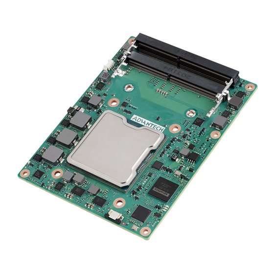
Summary of Contents for Advantech SOM-5993
- Page 1 User Manual SOM-5993 CPU Computer on Module...
- Page 2 No part of this manual may be reproduced, copied, translated, or transmitted in any form or by any means without the prior written permission of Advantech Co., Ltd. The information provided in this manual is intended to be accurate and reliable.
- Page 3 This product has passed the CE test for environmental specifications when shielded cables are used for external wiring. We recommend the use of shielded cables. This type of cable is available from Advantech. Please contact your local supplier for ordering information.
- Page 4 Discard used batteries according to the manufacturer's instructions.” Note! Notes provide additional optional information. Document Feedback To assist us with improving this manual, we welcome all comments and constructive criticism. Please send all feedback in writing to support@advantech.com. Selection Guide w/ P/N DDR4 Giga SATA...
- Page 5 Do not touch any components on the CPU card or other cards while the PC is powered on. Disconnect the power before making any configuration changes. A sudden rush of power after connecting a jumper or installing a card may damage sensitive electronic components. SOM-5993 User Manual...
- Page 6 In accordance with IEC 704-1:1982 specifications, the sound pressure level at the operator’s position does not exceed 70 dB (A). DISCLAIMER: These instructions are provided according to IEC 704-1 standards. Advantech disclaims all responsibility for the accuracy of any statements contained herein. SOM-5993 User Manual...
-
Page 7: Table Of Contents
I/O ....................9 1.3.10 Power Management..............11 1.3.11 Environment................11 1.3.12 MTBF ..................12 1.3.13 OS Support (duplicate with SW chapter) ........12 1.3.14 Advantech iManager ..............12 1.3.15 Power Consumption..............13 1.3.16 Performance ................13 1.3.17 Pin Description................13 Chapter Mechanical Information ....15... - Page 8 Figure 3.54PCI Express Root Port 7 .......... 71 Figure 3.55PCI Express Root Port 8 .......... 72 Figure 3.56PCI Express Root Port 9 .......... 73 Figure 3.57PCI Express Root Port 10 ........74 Figure 3.58PCI Express Root Port 11 ........75 SOM-5993 User Manual viii...
- Page 9 Driver Installation .................. 100 Windows Driver Setup................100 Other OS ....................100 Advantech iManager ................101 Appendix A Pin Assignment .......103 SOM-5993 Type 7 Pin Assignment............104 Appendix B Watchdog Timer ......109 Programming the Watchdog Timer ............110 Appendix C Programming GPIO ......111...
- Page 10 Table D.2: DMA Channel Assignments ........115 Interrupt Assignments ................116 Table D.3: Interrupt Assignments ..........116 1st MB Memory Map................116 Table D.4: 1st MB Memory Map ..........116 SOM-5993 User Manual...
-
Page 11: Chapter 1 General Information
Chapter General Information This chapter details background information on the SOM-5993 CPU Computer on Module. Sections include: Introduction Functional Block Diagram Product Specifications... - Page 12 Serial Presence Detect – refers to serial EEPROM on DRAMs that has DRAM Module configuration information Trusted Platform Module, chip to enhance the security features of a computer system UEFI Unified Extensible Firmware Interface Watchdog Timer SOM-5993 User Manual...
-
Page 13: Introduction
(9 ~ 12V; -40 ~ 85 °C) is ideal for diverse applications. In terms of software, SOM-5993 supports WISE-DeviceOn for remote hardware moni- toring and over the air software updates. SOM-5993 features 4 x screw holes near the CPU positioned in compliance with the ® Intel standard thermal design guide. -
Page 14: Functional Block Diagram
Functional Block Diagram SOM-5993 User Manual... -
Page 15: Product Specifications
1 (LPC) System Management R3.0 Type 7 SOM-5993 SDIO (Muxed on GPIO) General Purpose I/O SMBus 1 (Optional) Watchdog Timer Speaker Out External BIOS ROM Support Reset Function Trusted Platform Modules Power Management R3.0 Type 7 SOM-5993 SOM-5993 User Manual... -
Page 16: Processor System
Xeon D-1746TER 2.0 GHz 3.1 GHz 10/20 15MB Xeon D-1735TR 2.2 GHz 3.4 GHz 8/16 15MB Xeon D-1732TE 1.9 GHz 3.0 GHz 8/16 15MB Xeon D-1715TER 2.4 GHz 3.5 GHz 10MB Xeon D-1712TR 2.0 GHz 3.1 GHz 10MB SOM-5993 User Manual... -
Page 17: Memory
Processor D natively integrates 1 x PCIe x16 interface with support for up to 4 x devices at up to Gen4 speeds (8 GHz). SOM-5993 supports 1x PCIe x16, and is configurable to 4 x4, 2 x4 and 1 x8 or 1 x8 and 2 x4 or 2 x8. -
Page 18: Lpc
Processor D natively integrates 1 x PCI express x8 lanes and up to 4 x devices at up to Gen3 speeds (8.0 GT/s). SOM-5993 supports 1 PCIe x4 and 2 x2 in default, and is configurable to 4 x2, 1 x4 and 2 x2, 2 x2 and 1 x4 or 2 x4, 1 x8. -
Page 19: I/O
16-byte FIFO buffer on transmitter and receiver in FIFO mode Programmable serial-interface characteristics: 5, 6, 7, or 8-bit character Even, odd, or no parity bit selectable 1, 1.5, or 2 stop bit selectable SOM-5993 User Manual... - Page 20 Optional Setting Jumper 1-2 Purpose: The standard module has no jumper at SCN1. Therefore, the BIOS settings are maintained without a RTC coin battery. If you need to restore the BIOS default settings, please follow the steps below: SOM-5993 User Manual...
-
Page 21: Power Management
1.3.10.5 Advantech S5 ECO Mode (Deep Sleep Mode) Advantech iManager provides additional features that allow systems to enter a very low suspend power mode – S5 ECO mode. The module will cut all power including suspend and active power into the chipset and keep an on-module controller active in this mode. -
Page 22: Mtbf
1.3.13 OS Support (duplicate with SW chapter) The mission of Advantech Embedded Software Services is to "Enhance quality of life with Advantech platforms and Microsoft Windows embedded technology." We enable Windows Embedded software products on Advantech platforms to more effectively support the embedded computing community. -
Page 23: Power Consumption
1.3.17 Pin Description Advantech provides useful checklists for schematic design and layout routing. The schematic checklist will specify details about the electrical properties of each pin and how to connect it in different user scenarios. The layout checklist will specify the lay- out constraints and recommendations for trace length, impedance, and other neces- sary information during the design. - Page 24 SOM-5993 User Manual...
-
Page 25: Chapter 2 Mechanical Information
Chapter Mechanical Information This chapter details mechanical information on the SOM-5993 CPU Computer on Module. Sections include: Board Information Mechanical Diagram Assembly Diagram... -
Page 26: Board Information
Board Information The figures below indicate the main chips on SOM-5993 Computer-on-Module. Please be aware of these positions while designing customer carrier boards to avoid mechanical problems. Use thermal solution contacts for improved thermal perfor- mance. Figure 2.1 Board Chips Identification – Front Figure 2.2 Board Chips Identification –... -
Page 27: Connector List
Wafer 2.0 mm 3P 90D(M)DIP 2001-WR-03-LF W/Lock Pin Name Fan Tacho-Input Fan Out Mechanical Diagram For more information on 2D/3D models, please visit the Advantech COM support ser- vice website at: http://com.advantech.com. Figure 2.3 Board Mechanical Diagram — Front SOM-5993 User Manual... - Page 28 Figure 2.4 Board Mechanical Diagram – Back Figure 2.5 Board Mechanical Diagram – Side SOM-5993 User Manual...
-
Page 29: Assembly Drawing
Assembly Diagram These figures demonstrate the assembly order of the thermal module, COM module, and carrier board. Figure 2.6 Assembly Diagram There are 4 x reserved screw holes for SOM-5993 to be pre-assembled with heat spreader. SOM-5993 User Manual... -
Page 30: Assembly Drawing
Consider the CPU and chip height tolerance when designing your thermal solution. Figure 2.7 Main Chip Height and Tolerance Package height: 4.378 mm TOL:±0.242 mm (Post SMT stackup height based on limited data from Intel reference board design) SOM-5993 User Manual... -
Page 31: Chapter 3 Ami Bios
Chapter AMI BIOS This chapter details BIOS setup information for the SOM-5993 CPU computer-on module. Sections include: Introduction Entering Setup Hot/Operation Key Exit BIOS Setup Utility... -
Page 32: Introduction
Figure 3.1 Setup Program Initial Screen AMI's BIOS ROM has a built-in Setup program that allows users to modify the basic system configuration. This information is stored in flash ROM so it retains the Setup information when the power is turned off. SOM-5993 User Manual... -
Page 33: Entering The Setup
System Date using the <Arrow> keys. Enter new values through the keyboard. Press the <Tab> key or the <Arrow> keys to move between fields. The date must be entered in MM/DD/YY format. The time must be entered in HH:MM:SS format. SOM-5993 User Manual... -
Page 34: Advanced Bios Features Setup
Advanced BIOS Features Setup Select the Advanced tab from the SOM-5993 setup screen to enter the Advanced BIOS Setup screen. Users can select any item in the left frame of the screen, such as CPU Configuration, to go to the sub menu for that item. Users can display an Advanced BIOS Setup option by highlighting it using the <Arrow>... -
Page 35: Trusted Computing
Figure 3.4 Trusted Computing Security Device Support SHA-A PCR Bank SHA256 PCR Bank Pending operation Platform Hierarchy Endorsement Hierarchy TPM 2.0 UEFI Spec Version Physical Presence Spec Version Device Select SOM-5993 User Manual... -
Page 36: Acpi Settings
3.4.2 ACPI Settings Figure 3.5 ACPI Settings Enable ACPI Auto Configuration SOM-5993 User Manual... -
Page 37: Embedded Controller
Figure 3.6 Embedded Controller CPU Shutdown Temperature Smart Fan – COM Module Smart Fan – Carrier Board Power Saving Mode Serial Port 1 Configuration Serial Port 2 Configuration Hardware Monitor SOM-5993 User Manual... - Page 38 3.4.3.1 Serial Port 1 Configuration Figure 3.7 Serial Port 1 Configuration Serial Port Change Settings SOM-5993 User Manual...
- Page 39 3.4.3.2 Serial Port 2 Configuration Figure 3.8 Serial Port 2 Configuration Serial Port Change Settings 3.4.3.3 Hardware Monitor Figure 3.9 Hardware Monitor SOM-5993 User Manual...
- Page 40 3.4.4 Serial Port Console Redirection Figure 3.10 Serial Port Console Redirection Console Redirection Console Redirection Settings. Console Redirection EMS Console Redirection Settings. SOM-5993 User Manual...
- Page 41 Figure 3.11 Console Redirection Settings Terminal Type Bits per second Data Bits Parity Stop Bits Flow Control VT-UTF8 Combo Key Support Recorder Mode Resolution 100x31 Putty KeyPad SOM-5993 User Manual...
- Page 42 3.4.4.2 Console Redirection Settings Figure 3.12 Console Redirection Settings Out-Of-Band Mgmt Port Terminal Type EMS Bits per second EMS Flow Control EMS SOM-5993 User Manual...
- Page 43 PCI Latency Timer PCI-X Latency Timer VGA Palette Snoop PERR# Generation SERR# Generation Above 4G Decoding SR-IOV Support BME DMA Mitigation PCI Express Settings PCI Express GEN 2 Settings SOM-5993 User Manual...
- Page 44 Figure 3.14 PCI Express Settings Relaxed Ordering Extended Tag No Snoop Maximum Payload Maximum Read Request ASPM Support Extended Synch Link Training Retry Link Training Timeout (uS) Unpopulated Links SOM-5993 User Manual...
- Page 45 AtomicOp Egress Blocking DO Request Enable LTR Mechanism Enable End-End TLP Prefix Blocking Target Link Speed Clock Power Management Compliance SOS Hardware Autonomous Width Hardware Autonomous Speed SOM-5993 User Manual...
- Page 46 Figure 3.16 USB Configuration Legacy USB Support XHCI Hand-off USB Mass Storage Driver Support USB transfer time-out Device reset time-out Device power-up delay AMI Virtual CDROMO 1.00 AMI Virtual HDISK0 1.00 SOM-5993 User Manual...
- Page 47 3.4.7 Network Stack Configuration Figure 3.17 Network Stack Configurations Network Stack 3.4.8 NVMe Configuration Figure 3.18 NVMe Configuration SOM-5993 User Manual...
- Page 48 Chipset Select the Chipset tab from the SOM-5993 setup screen to enter the BIOS Setup screen. You can select the items by highlighting it using by the <Arrow> keys. All Plug and Play BIOS Setup options are described in this section. The Plug and Play BIOS Setup screen is shown below.
- Page 49 3.5.1 Socket Configuration Figure 3.20 Socket Configuration Processor Configuration IIO Configuration Advanced Power Management Configuration Memory Topology SOM-5993 User Manual...
- Page 50 3.5.1.1 Processor Configuration Figure 3.21 Processor Configuration Figure 3.22 Processor Configuration SOM-5993 User Manual...
- Page 51 DCU IP Prefetcher LLC Prefetcher DCU Mode Bsp Selection Extended APIC APIC Physical Mode PECI Legacy Agent SMBus Agent IS Agent Generic Agent eSPI Agent DBP-F SOM-5993 User Manual...
- Page 52 #AC Exception On Split Lock Total Memory Encryption (TME) Limit CPU PA to 46 bits PSMI Configuration RDT CAT Opportunistic Tuning Per-Socket Configuration Figure 3.24 Per-Socket Configuration CPU Socket 0 Configuration SOM-5993 User Manual...
- Page 53 CPU Socket 0 Configuration Figure 3.25 CPU Socket 0 Configuration Core Disable Bitmap (Hex) SOM-5993 User Manual...
- Page 54 PSMI Configuration Figure 3.26 PSMI Configuration Global PSMI Enable Socket 0 Configuration SOM-5993 User Manual...
- Page 55 Socket 0 Configuration Figure 3.27 Socket 0 Configuration PSMI Enabled SOM-5993 User Manual...
- Page 56 Mask PCIe RP warm reset MCA PCIe Low Latency Retimers Skip PCIe retimers detection PCI-E Completion Timerout PCI-E Completion Timerout PCI-E ASPM Support (Global) PCIe Max Read Request Size SOM-5993 User Manual...
- Page 57 Figure 3.29 Socket0 Configuration IOU0 (IIO PCIe Port 1) Sck0 RP Correctable Err Sck0 RP NonFatal Uncorrectable Err Sck0 RP Fatal Uncorrectable Err TraceHub Configuration Menu R-Link Port 1A SOM-5993 User Manual...
- Page 58 TraceHub Configuration Menu Figure 3.30 TraceHub Configuration Menu North Trace Hub Enable Mode R-Link Figure 3.31 R-Link SOM-5993 User Manual...
- Page 59 PCI-E Completion Timeout PCI-E ASPM Support PCI-E Extend Sync Compliance Mode Unsupported Request Alternate TxEq Alt ATTEN Table SRIS ECRC Generation ECRC Check SERRE MCTP SOM-5993 User Manual...
- Page 60 Port 1A Figure 3.33 Port 1A SOM-5993 User Manual...
- Page 61 PCI-E Completion Timeout PCI-E ASPM Support PCI-E Extend Sync Compliance Mode Unsupported Request Alternate TxEq Alt ATTEN Table SRIS ECRC Generation ECRC Check SERRE MCTP SOM-5993 User Manual...
- Page 62 3.5.1.3 Advanced Power Management Configuration Figure 3.35 Advanced Power Management Configuration CPU P State Control CPU C State Control Package C State Control SOM-5993 User Manual...
- Page 63 CPU P State Control Figure 3.36 CPU P State Configuration SpeedStep (Pstates) Boot performance mode Energy Efficient Turbo Turbo Mode CPU Flex Ratio Override Perf P-Limit SOM-5993 User Manual...
- Page 64 Perf P-Limit Figure 3.37 Perf P-Limit Perf P-Limit Differential Perf P-Limit Clip Perf P-Limit Threshold SOM-5993 User Manual...
- Page 65 CPU C State Control Figure 3.38 CPU C State Configuration Enable Monitor MWAIT CPU C1 auto demotion CPU C1 auto undemotion CPU C6 report Enhanced Halt State (C1E) OS ACPI CX SOM-5993 User Manual...
- Page 66 C2C3TT Dynamic L1 PKG C-state Lat. Neg. LTR IIO Input Latency Tolerance Requirement (LTR) Enable PKGC_SA_PS_CRITERIA PKGC SA PS Criteria Power Management Control MDLL Off PKGc Interrupt Response Time SOM-5993 User Manual...
- Page 67 Latency Tolerance Requirement (LTR) Figure 3.40 Latency Tolerance Requirement (LTR) PCIe LTR Override Control SOM-5993 User Manual...
- Page 68 PkgC SA PS Criteria Power Management Control Figure 3.41 PkgC SA PS Criteria Power Management Control CPU0 PKGC_SA_PS_CRITERIA SOM-5993 User Manual...
- Page 69 CPU0 PKGC_SA_PS_CRITERIA Figure 3.42 CPU0 PKGC_SA_PS_CRITERIA CPU0 Logical_ip_type PKGC_CRITERIA KTI SOM-5993 User Manual...
- Page 70 PKGc Interrupt Response Time Figure 3.43 PKGc Interrupt Response Time VALID: VALID: VALID: SOM-5993 User Manual...
- Page 71 3.5.1.4 Memory Topology Figure 3.44 Memory Topology SOM-5993 User Manual...
- Page 72 3.5.2 Platform Configuration Figure 3.45 Platform Configuration PCH-IO Configuration System Event Log SOM-5993 User Manual...
- Page 73 PCH-IO Configuration Figure 3.46 PCH-IO Configuration PCI Express Configuration Fia Mux Configuration SATA Configuration USB Configuration Security Configuration State After G3 Pcie Pll SSC Flash Protection Range Registers (FPRR) SOM-5993 User Manual...
- Page 74 PCI Express Root Port 7 PCI Express Root Port 8 PCI Express Root Port 9 PCI Express Root Port 10 PCI Express Root Port 11 PCI Express Root Port 12 SOM-5993 User Manual...
- Page 75 PCI Express Root Port 1 Figure 3.48 PCI Express Root Port 1 PCI Express Root Port 1 ASPM L1 Substates Hot Plug PCIe Speed SOM-5993 User Manual...
- Page 76 PCI Express Root Port 2 Figure 3.49 PCI Express Root Port 2 PCI Express Root Port 2 ASPM L1 Substates Hot Plug PCIe Speed SOM-5993 User Manual...
- Page 77 PCI Express Root Port 3 Figure 3.50 PCI Express Root Port 3 PCI Express Root Port 3 ASPM L1 Substates Hot Plug PCIe Speed SOM-5993 User Manual...
- Page 78 PCI Express Root Port 4 Figure 3.51 PCI Express Root Port 4 PCI Express Root Port 4 ASPM L1 Substates Hot Plug PCIe Speed SOM-5993 User Manual...
- Page 79 PCI Express Root Port 5 Figure 3.52 PCI Express Root Port 5 PCI Express Root Port 5 ASPM L1 Substates Hot Plug PCIe Speed SOM-5993 User Manual...
- Page 80 PCI Express Root Port 6 Figure 3.53 PCI Express Root Port 6 PCI Express Root Port 6 ASPM L1 Substates Hot Plug PCIe Speed SOM-5993 User Manual...
- Page 81 PCI Express Root Port 7 Figure 3.54 PCI Express Root Port 7 PCI Express Root Port 7 ASPM L1 Substates Hot Plug PCIe Speed SOM-5993 User Manual...
- Page 82 PCI Express Root Port 8 Figure 3.55 PCI Express Root Port 8 PCI Express Root Port 8 ASPM L1 Substates Hot Plug PCIe Speed SOM-5993 User Manual...
- Page 83 PCI Express Root Port 9 Figure 3.56 PCI Express Root Port 9 PCI Express Root Port 9 ASPM L1 Substates Hot Plug PCIe Speed SOM-5993 User Manual...
- Page 84 PCI Express Root Port 10 Figure 3.57 PCI Express Root Port 10 PCI Express Root Port 10 ASPM L1 Substates Hot Plug PCIe Speed SOM-5993 User Manual...
- Page 85 PCI Express Root Port 11 Figure 3.58 PCI Express Root Port 11 PCI Express Root Port 11 ASPM L1 Substates Hot Plug PCIe Speed SOM-5993 User Manual...
- Page 86 PCI Express Root Port 12 Figure 3.59 PCI Express Root Port 12 PCI Express Root Port 12 ASPM L1 Substates Hot Plug PCIe Speed SOM-5993 User Manual...
- Page 87 Fia Mux Configuration Figure 3.60 Fia Mux Configuration Figure 3.61 Fia Mux Configuration SOM-5993 User Manual...
- Page 88 Figure 3.62 Fia Mux Configuration Figure 3.63 Fia Mux Configuration SOM-5993 User Manual...
- Page 89 Lane 5 Lane 6 PCIe RP link width Lane 7 Lane 8 PCIe RP link width Lane 9 PCIe RP link width Lane 10 PCIe RP link width SOM-5993 User Manual...
- Page 90 Lane 17 Lane 18 Lane 19 Lane 20 Lane 21 Lane 22 Lane 23 SATA Configuration Figure 3.65 SATA Configuration SATA Controller Speed Controller 3 SATA Configuration SOM-5993 User Manual...
- Page 91 Controller 3 SATA Configuration Figure 3.66 Controller 3 SATA Configuration SATA Configuration Aggressive LPM Support Port 2 Port 3 SOM-5993 User Manual...
- Page 92 USB Configuration Figure 3.67 USB Configuration USB Port Disable Override SOM-5993 User Manual...
- Page 93 Security Configuration Figure 3.68 Security Configuration BIOS Lock SOM-5993 User Manual...
- Page 94 CrashLog Feature CrashLog On All Reset Shutdown Suppression eMCA Settings Whea Settings Error Injection Settings Memory Error Enabling IIO Error Enabling PCIe Error Enabling Error Control Setting SOM-5993 User Manual...
- Page 95 Ignore OS EMCA Opt-in EMCA CMCI-SMI Morphing EMCA CMCI-SMI Threshold CSMI Dynamic Disable EMCA MCE-SMI Enable Corrected Error elog Memory Error elog Processor Error elog Ubox Error Mask SOM-5993 User Manual...
- Page 96 Whea Settings Figure 3.71 Whea Settings WHEA Support Whea Log Memory Error Whea Log Processor Error Whea Log PCI Error SOM-5993 User Manual...
- Page 97 Error Injection Settings Figure 3.72 Error Injection Settings WHEA Error Injection Support SOM-5993 User Manual...
- Page 98 Memory Error Enabling Figure 3.73 Memory Error Enabling Memory Error Memory Corrected Error Spare Interrupt SOM-5993 User Manual...
- Page 99 IIO Error Enabling Figure 3.74 IIO Error Enabling Figure 3.75 IIO Error Enabling IIO/PCH Global Error Support Os Native AER Support SOM-5993 User Manual...
- Page 100 IIO PCIE Additional Corrected Error IIO PCIE Additional Uncorrected Error IIO PCIE Additional Received Completion With UR IIO PCIE AER Spec Compliant ITC/OTC CA/MA Errors PSF UR Error PMSB Router Parity Error SOM-5993 User Manual...
- Page 101 PCIe Error Enabling Figure 3.76 PCIe Error Enabling Figure 3.77 PCIe Error Enabling Corrected Error Uncorrected Error SOM-5993 User Manual...
- Page 102 Gen3/4 Re-Equalization Gen2 Link Degradation Gen3 Link Degradation Gen4 Link Degradation Error Control Setting Figure 3.78 Error Control Setting Latch First Corrected Error in KTI Partrol Scrub Error Reporting SOM-5993 User Manual...
-
Page 103: Server Mgmt
Server Mgmt Figure 3.79 Server Mgmt BMC Support SOM-5993 User Manual... -
Page 104: Security
Security Figure 3.80 Security Administration Password User Password Secure Boot SOM-5993 User Manual... -
Page 105: Secure Boot
3.7.1 Secure Boot Figure 3.81 Secure Boot Secure Boot Secure Boot Mode SOM-5993 User Manual... -
Page 106: Boot
Boot Figure 3.82 Boot Setup Prompt Timeout Bootup Numlock State Quiet Boot Boot Option #1 SOM-5993 User Manual... -
Page 107: Save And Exit
Save Changes and Exit Discard Changes and Exit Save Changes and Reset Discard Changes and Reset Save Changes Discard Changes Restore Defaults Save as User Defaults Restore User Defaults SOM-5993 User Manual... - Page 108 SOM-5993 User Manual...
-
Page 109: S/W Introduction & Installation
Chapter S/W Introduction & Installation S/W Introduction Driver Installation Advantech iManager... -
Page 110: S/W Introduction
S/W Introduction The mission of Advantech Embedded Software Services is to "Enhance quality of life with Advantech platforms and Microsoft Windows embedded technology." We enable Windows Embedded software products on Advantech platforms to more effectively support the embedded computing community. Customers are freed from the hassle of dealing with multiple vendors (hardware suppliers, system integrators, embedded OS distributor) for projects. -
Page 111: Advantech Imanager
For more details on how to use the APIs and utilities, please refer to Advantech iManager 2.0 Software API User Manual. - Page 112 SOM-5993 User Manual...
-
Page 113: Appendix A Pin Assignment
Appendix Pin Assignment This appendix details information on the hardware pin assignment of the SOM-5993 CPU System on Module. Sections include: SOM-5993 Type 7 Pin Assign- ment... -
Page 114: Som-5993 Type 7 Pin Assignment
SOM-5993 Type 7 Pin Assignment This section details the SOM-5993 pin assignment on COM Express connector which is compliant with COM Express R3.0 Type 7 pin-out definitions. To receive further details on using these pins, or to receive a design reference, please contact Advant- ech. - Page 115 WAKE0# GPI2 WAKE1# PCIE_TX0+ PCIE_RX0+ PCIE_TX0- PCIE_RX0- GND(FIXED) GND(FIXED) PCIE_TX8+ PCIE_RX8+ PCIE_TX8- PCIE_RX8- PCIE_TX9+ PCIE_RX9+ PCIE_TX9- PCIE_RX9- PCIE_TX10+ PCIE_RX10+ PCIE_TX10- PCIE_RX10- GND(FIXED) GND(FIXED) PCIE_TX11+ PCIE_RX11+ PCIE_TX11- PCIE_RX11- NCSI_TX_EN VCC_5V_SBY GPI3 VCC_5V_SBY RSVD VCC_5V_SBY RSVD VCC_5V_SBY PCIE_CK_REF+ BIOS_DIS1# SOM-5993 User Manual...
- Page 116 B106 VCC_12V A107 VCC_12V B107 VCC_12V A108 VCC_12V B108 VCC_12V A109 VCC_12V B109 VCC_12V A110 GND(FIXED) B110 GND(FIXED) SOM-5993 ROW C, D GND(FIXED) GND(FIXED) USB_SSRX0- USB_SSTX0- USB_SSRX0+ USB_SSTX0+ USB_SSRX1- USB_SSTX1- USB_SSRX1+ USB_SSTX1+ USB_SSRX2- USB_SSTX2- USB_SSRX2+ USB_SSTX2+ GND(FIXED) GND(FIXED) USB_SSRX3- USB_SSTX3-...
- Page 117 PEG_RX0+ PEG_TX0+ PEG_RX0- PEG_TX0- PEG_RX1+ PEG_TX1+ PEG_RX1- PEG_TX1- PEG_RX2+ PEG_TX2+ PEG_RX2- PEG_TX2- GND(FIXED) GND(FIXED) PEG_RX3+ PEG_TX3+ PEG_RX3- PEG_TX3- RSVD RSVD RSVD RSVD PEG_RX4+ PEG_TX4+ PEG_RX4- PEG_TX4- RAPID_SHUTDOWN PEG_RX5+ PEG_TX5+ PEG_RX5- PEG_TX5- GND(FIXED) GND(FIXED) PEG_RX6+ PEG_TX6+ PEG_RX6- PEG_TX6- SOM-5993 User Manual...
- Page 118 PEG_RX15+ D101 PEG_TX15+ C102 PEG_RX15- D102 PEG_TX15- C103 D103 C104 VCC_12V D104 VCC_12V C105 VCC_12V D105 VCC_12V C106 VCC_12V D106 VCC_12V C107 VCC_12V D107 VCC_12V C108 VCC_12V D108 VCC_12V C109 VCC_12V D109 VCC_12V C110 GND(FIXED) D110 GND(FIXED) SOM-5993 User Manual...
-
Page 119: Appendix B Watchdog Timer
Appendix Watchdog Timer This appendix details information regarding the watchdog timer programming for the SOM-5993 CPU System on Module. Sections include: Watchdog Timer Programming... -
Page 120: Programming The Watchdog Timer
** WDT new driver support automatically select available IRQ number from BIOS, and then set to EC. Only Win8.1 and Win10 support it. In other OS, it will still use IRQ number from BIOS setting as usual. For details, please refer to iManager & Software API User Manual: SOM-5993 User Manual... -
Page 121: Appendix C Programming Gpio
Appendix Programming GPIO This appendix provides a General Purpose Input and Output pin set- ting diagram. Sections include: System I/O ports... -
Page 122: Gpio Register
GPIO Register GPIO Byte Mapping H/W Pin Name BIT0 GPO0 BIT1 GPO1 BIT2 GPO2 BIT3 GPO3 BIT4 GPI0 BIT5 GPI1 BIT6 GPI2 BIT7 GPI3 For details, please refer to iManager & Software API User Manual. SOM-5993 User Manual... -
Page 123: Appendix D System Assignments
Appendix System Assignments This appendix details information on the system resource alloca- tion of the SOM-5993 CPU System on Module. Sections include: System I/O Ports DMA Channel Assignments Interrupt Assignments 1 MB Memory Map... -
Page 124: System I/O Ports
0x000002F0-0x000002F7 Motherboard resources 0x000002F8-0x000002FF Communications Port (COM2) 0x00000300-0x0000037F Motherboard resources 0x000003B0-0x000003BB CDF PCIeRP[2] - 18A6 0x000003B0-0x000003BB PCI Express to PCI/PCI-X Bridge 0x00003000-0x00003FFF CDF PCIeRP[3] - 18A7 0x000003C0-0x000003DF CDF PCIeRP[2] - 18A6 0x000003C0-0x000003DF PCI Express to PCI/PCI-X Bridge SOM-5993 User Manual... -
Page 125: Dma Channel Assignments
CDF HSUART - 18D8 0x00005070-0x00005073 Standard SATA AHCI Controller 0x00005080-0x00005087 Standard SATA AHCI Controller 0x00006000-0x0000AFFF PCI Express Root Complex 0x0000B000-0x0000FFFF PCI Express Root Complex DMA Channel Assignments Table D.2: DMA Channel Assignments Channel Function Direct memory access controller SOM-5993 User Manual... - Page 126 Intel(R) I210 Gigabit Network Connection 0xB0480000-0xB04FFFFF Intel(R) I210 Gigabit Network Connection 0xB0580000-0xB05FFFFF Intel (R) PMON MSM Registers - 09A7 0xB0600000-0xB067FFFF Intel (R) PMON MSM Registers - 09A7 0xB0680000-0xB0681FFF Standard SATA AHCI Controller 0xB0682000-0xB0683FFF Intel (R) MSM Registers - 09A6 SOM-5993 User Manual...
- Page 127 CDF PCIeRP[2] - 18A6 Intel(R) USB 3.0 eXtensible Host Controller - 1.0 (Micro- 0xFFA80000-0xFFA8FFFF soft) 0xFFAB8000-0xFFAB8FFF CDF ME:HECI#3 - 18D6 0xFFAB9000-0xFFAB9FFF CDF ME:HECI#2 - 18D4 0xFFABA000-0xFFABAFFF CDF ME:HECI#1 - 18D3 0xFFFFF000-0xFFFFFFFF SDA Standard Compliant SD Host Controller SOM-5993 User Manual...
- Page 128 No part of this publication may be reproduced in any form or by any means, such as electronically, by photocopying, recording, or otherwise, without prior written permission from the publisher. All brand and product names are trademarks or registered trademarks of their respective companies. © Advantech Co., Ltd. 2022...
Need help?
Do you have a question about the SOM-5993 and is the answer not in the manual?
Questions and answers