Table of Contents
Advertisement
Quick Links
Advertisement
Table of Contents

Subscribe to Our Youtube Channel
Related Manuals for Advantech ARK-3532


Summary of Contents for Advantech ARK-3532
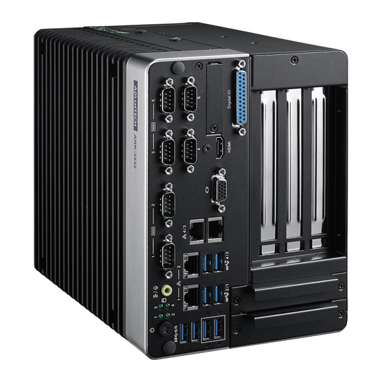
- Page 1 User Manual ARK-3532 Fanless Embedded Box PC...
- Page 2 This package contains a hard-copy user manual in Chinese for China CCC certifica- tion purposes. There is an English user manual included as a PDF file on the CD. Please disregard the Chinese hard copy user manual if the product is not to be sold and/or installed in China. ARK-3532 User Manual...
- Page 3 The documentation and the software included with this product are copyrighted 2021 by Advantech Co., Ltd. All rights are reserved. Advantech Co., Ltd. reserves the right to make improvements in the products described in this manual at any time without notice.
- Page 4 Because of Advantech’s high quality-control standards and rigorous testing, most of our customers never need to use our repair service. If an Advantech product is defec- tive, it will be repaired or replaced at no charge during the warranty period. For out- of-warranty repairs, you will be billed according to the cost of replacement materials, service time and freight.
- Page 5 Technical Support and Assistance Visit the Advantech website at www.advantech.com/support where you can find the latest information about the product. Contact your distributor, sales representative, or Advantech's customer service center for technical support if you need additional assistance. Please have the following information ready before you call: –...
- Page 6 Power cable 3-pin 183 cm (6 ft), USA type 1702002605 Power cable 3-pin 183 cm (6 ft), EU type 1702031801 Power cable 3-pin 183 cm (6 ft), UK type 1700000237 Power cable 3-Pin 183 cm (6 ft), PSE type ARK-3532 User Manual...
- Page 7 70 dB (A). The equipment should only be installed in a restricted access areas. DISCLAIMER: These instructions are provided according to IEC 704-1 specifi- cations. Advantech disclaims all responsibility for the accuracy of any statements con- tained herein. ARK-3532 User Manual...
- Page 8 This product is intended to be supplied by a UL Listed power supply suitable for use at minimum Tma 50 °C (122 °F) whose output meets PS2 (or LPS), ES1(or SELV) and output is rated: 9-36Vdc, 16.65-4.16A. Please contact Advantech for further information.
- Page 9 L'équipement ne doit être installé que dans une zone d'accès restreint. AVERTISSEMENT: Cet ensemble d'instructions est donné conformément à la norme CEI 704-1. Advantech décline toute responsabilité quant à l'exactitude des déclarations contenues dans ce. Au moyen d'un cordon d'alimentation connecté à une prise de courant avec mise à...
- Page 10 ARK-3532 User Manual...
-
Page 11: Table Of Contents
Jumper Settings ................12 Connectors....................14 2.3.1 ARK-3532 External I/O Locations ..........14 Figure 2.2 ARK-3532 Front and Rear I/O Connector Diagram.. 14 Figure 2.3 COM Connector............14 Table 2.2: COM Connector Pin Assignments......14 Table 2.3: COM Connector Pin Assignments......15 Figure 2.4 Ethernet Connector .......... - Page 12 Save & Exit ................. 83 Appendix A Watchdog Timer Sample Code ..85 EC Watchdog Timer Sample Code ............86 Appendix B Fixing the LAN order ......87 Problem Statement ................. 88 Addressing the LAN Order..............89 ARK-3532 User Manual...
-
Page 13: Chapter 1 General Introduction
Chapter General Introduction This chapter details background information on the ARK-3532 series. -
Page 14: Introduction
(Up to 4 x 2.5” SATAIII HDD bays by optional AMK-A0035). Rugged Multi-Functional Design ARK-3532 adopts an advanced thermal design for its desktop processor solution. All models are fanless, and deliver several unique features. These include wide operat- ing temperatures (-20 ~ 60 °C / -4 ~ 140 °F), diverse expandability options, and struc- tural strengthening. -
Page 15: Product Features
– 1 x Full size MiniPCIe (support mSATA and 1 with SIM) – 1 x M.2 (E key for Wi-Fi, suggested installation at Advantech manufacturing) – Add-on Card Slot:3532B for 1 Slot PCIex4+ 1 Slot PCIex16, 3532C for 1 Slot PCIex4 + 2 Slot PCI,3532D for 1 Slot PCIex4 + 2 Slot PCI + 1 Slot PCIex16 TPM: TPM 2.0 (Optional) -
Page 16: Chipset
Maximum 500mA for each USB port Power Management Intel® W480E chip supports: Supports ACPI ACPI-defined power states (processor driven C states) ACPI Power Management Timer SMI# generation BIOS Intel® W480E chip supports: ARK-3532 User Manual... -
Page 17: Susi 4.0
SUSI API Sequence Control Supported DIO 16-bit programmable DIO Watchdog Timer Multi-level WDT (set by Advantech iManager) Programmable 1-255 sec / min Hardware Monitor CPU Temperature / input Current / input Voltage System Information Running HR / Boot record ... -
Page 18: Mechanical Specifications
Mechanical Specifications 1.4.1 Dimensions ARK-3532B/ARK-3532C (W x H x D) 156 x 204 x 230 mm/6.14 x 8.03 x 9.05 in ARK-3532 User Manual... -
Page 19: Weight
ARK3532B/ARK3532C: 5.7 kg (12.5 lb) ARK3532D: 6.41 kg (14.1 lb) Power Requirements 1.5.1 System power Minimum Power Input: 9 ~ 36VDC Optional Adapter: – 150W @19V/7.89A power adapter (optional) – 230W @ 24V/9.58A power adapter (optional) ARK-3532 User Manual... -
Page 20: Operating Environment Specifications
1.6.2 Relative humidity 95% @ 40 °C (104 °F) (non-condensing) 1.6.3 Storage temperature -40 ~ 85 °C (-40 ~ 185 °F) 1.6.4 Safety UL, CB, CCC, BSMI 1.6.5 CE/FCC Class B, CCC, BSMI ARK-3532 User Manual... -
Page 21: Chapter 2 Hardware Configuration
Chapter Hardware Configuration... -
Page 22: Introduction
2.2.1 Jumper Description You may configure ARK-3532 to match the needs of your application by setting jump- ers. A jumper is a metal bridge used to close an electric circuit. It consists of two metal pins and a small metal clip (often protected by a plastic cover) that slides over the pins to connect them. -
Page 23: Jumper Locations
2.2.3 Jumper Locations Figure 2.1 Jumper Layout ARK-3532 User Manual... -
Page 24: Jumper Settings
(2-3) Clear CMOS 2.2.4.3 MINI PCIE Power setting for MPWR_SEL1 MPWR_SEL1 Power Setting Part Number 1653003101 Footprint HD_3x1P_79_D Description PIN HEADER 3x1P 2.0mm 180D(M) DIP 2000-13 WS Setting Function (1-2) 3.3V (Default) (2-3) 3.8V for 5G module ARK-3532 User Manual... - Page 25 11 = 1 x16 PCI Express* (Default) 2.2.4.6 COM3 RI power setting J1 (AMO-I028) on AMO-I028 card J1 (AMO-I028) RI power setting Part Number 1653003201 Footprint HD_3x2P_79_D Description PIN HEADER 3x2P 2.0mm 180D(M) DIP 21N22050 Setting Function (1-2) Normal (default) (3-4) (5-6) +12V ARK-3532 User Manual...
-
Page 26: Connectors
COM Connector ARK-3532 provides up to 6 D-sub 9-pin connectors, which offers RS-232/422/485 serial communication interface ports. The default setting is RS-232, the mode RS-422/ 485 of ARK-3532 COM3/4/5/6 can be supported via the BIOS settings. COM1/2 sup- ports RS-232. COM3~COM6 ... - Page 27 2.3.1.2 Ethernet Connector (LAN) ARK-3532 is equipped with up to 4 x (LAN3/4 are optional by TPN support) Ethernet controllers that are fully compliant with IEEE 802.3u 10/100/1000 Mbps CSMA/CD standards. These Ethernet ports provides a standard RJ-45 jack connector with LED indicators on the front side to show its Active/Link status (Green LED) and Speed sta- tus (Green/Orange LED).
- Page 28 Hot Plug Detect 2.3.1.4 VGA Connector ARK-3532 provides an integrated 15-pin female VGA digital video interface, which supports up to 1920 x 1200 @ 60 Hz. Please refer to Table 2.6 for its pin assign- ments. Figure 2.6 VGA Connector...
- Page 29 Port0 D0 Port1 D8 Port0 D1 Port1 D9 Port0 D2 Port1 D10 Port0 D3 Port1 D11 Port0 D4 Port1 D12 Port0 D5 Port1 D13 Port0 D6 Port1 D14 Port0 D7 Port1 D15 Note! NC represents “No Connection”. ARK-3532 User Manual...
- Page 30 2.3.1.9 USB3.2 Gen2 and Gen1 ARK-3532 supports 4 x USB 3.2 (Gen2,10G), 2 x USB 3.2 (Gen1, 5G), and 2 x Inde- pendent USB 3.2 (Gen1, 5G) interfaces The USB interfaces complies with USB UHCI, Rev. 3.0 standards. Please refer to Table 2.5 for its pin assignments. USB 3.2 Gen1/2 connectors contain legacy pins to interface with USB 2.0 devices, and a new...
-
Page 31: Installation
2.3.1.10 Remote Switch Connector ARK-3532 provides the remote switch connector for power on/off with a external cable. From the left to the right are Reset, GND, and Power Switch On. Installation 2.4.1 CPU/Memory Installation Unscrew the 4 screws from- the top cover, and remove the top cover. - Page 32 Install the CPU (LGA1151) and memory into the system. Replace the top cover. ARK-3532 User Manual...
-
Page 33: External Hdd/Ssd Installation
Push back the hard drive bay into the system and secure it using the same screws. 2.4.3 Mounting Kit Installation Take out mounting kit and 4 screws (M3x6L) from the accessory box. Retirez le kit de montage et les 4 vis (M3x6L) de la boîte d'accessoires. ARK-3532 User Manual... -
Page 34: Module/Minipcie Module/Internal Sim Card Slot Installation
Screw one of the 2 screws (M3x6L) on left and right side and secure the system horizontally. Vissez chaque 2 vis (M3x6L) sur les côtés gauche et droit et fixez le système horizontalement. 2.4.4 M.2 Module/MiniPCIe Module/Internal SIM Card Slot Installation ARK-3532 User Manual... -
Page 35: Paste The Thermal Pad
2.4.5 Paste the Thermal pad Take the thermal pad from the accessory box). Paste the 30 x 30 x 0.2mm Thermal Pad on the CPU (as illustrated). Paste 46.7 x 46.7x1mm on the Copper block (as illustrated). ARK-3532 User Manual... - Page 36 ARK-3532 User Manual...
-
Page 37: Bios Settings
Chapter BIOS Settings... -
Page 38: Introduction
AMIBIOS has been integrated into motherboards for over two decades. With the AMIBIOS Setup program, users can modify BIOS settings and control various sys- tem features. This chapter describes the basic navigation of the ARK-3532 BIOS setup screens. AMI's BIOS ROM has a built-in setup program that allows users to modify the basic system configuration. -
Page 39: Entering The Setup
BIOS supports your CPU. If there is no number assigned to the patch code, please contact an Advantech application engineer to obtain an up-to-date patch code file. This will ensure that your CPU‘s system status is valid. -
Page 40: Advanced Bios Features Setup
3.2.2 Advanced BIOS Features Setup Select the Advanced tab from the ARK-3532 setup screen to enter the Advanced BIOS Setup screen. Users can select any item in the left frame of the screen, such as CPU Configuration, to go to the sub menu for that item. Users can display an Advanced BIOS Setup option by highlighting it using the <Arrow>... - Page 41 This option configures Connectivity. Discrete Bluetooth Module SerialIo UART0 needs to be enabled to select BT Module. Advanced settings Configure ACPI objects for wireless devices. WWAN Configuration – WWAN Device Enable or Disable M.2 WWAN Device. ARK-3532 User Manual...
- Page 42 3.2.2.2 CPU Configuration C6DRAM Enable/Disable moving of DRAM contents to PRM memory when CPU is in C6 state. Software Guard Extensions (SGX) Enable/Disable Software Guard Extensions (SGX). ARK-3532 User Manual...
- Page 43 FCLK frequency can take values of 400MHz, 800MHz and 1GHz.(1GHz not supported for ULT/ULX SKUs) Voltage Optimization Auto: This Option will honor the Silicon default values; ENABLE - Mobile SKU's, DISABLE - Rest of all SKUs other than Mobile. ARK-3532 User Manual...
- Page 44 Enable/Disable usage of SMM_DELAYED MSR for MP sync in SMI. – SMM Use Block Indication Enable/Disable usage of SMM_BLOCKED MSR for MP sync in SMI. – DGR+NR11 / NR10 Support Select DGR with Nifty Rock11 or Nifty Rock10 Feature. ARK-3532 User Manual...
- Page 45 3.2.2.3 Power and Performance – CPU Power Management Control ARK-3532 User Manual...
- Page 46 Platform PL2 Power Platform Power Limit 2 Power in Milli Watts. Power Limit 4 Override Enable/Disable Power Limit 4 override. Power Limit 4 Power Limit 4 in Milli Watts. Power Limit 4 Lock ARK-3532 User Manual...
- Page 47 Limit 4 MSR 601h Lock. When enabled PL4 configurations are locked during OS. When disabled PL4 configuration can be changed during OS. C states Enable/Disable CPU Power Management. ARK-3532 User Manual...
- Page 48 255). Min = Max Non-Turbo Ratio. Max = fused turbo ratio, or 255 if CPU is unlocked for overclocking. – Energy Efficient Turbo Enable/Disable Energy Efficient Turbo Feature. This feature will opportunisti- cally lowers the turbo frequency to increase efficiency. ARK-3532 User Manual...
- Page 49 – Number of P states Sets the number of custom P-states. At least 2 states must be present. ARK-3532 User Manual...
- Page 50 – Power Limit 3 Override Enable/Disable Power Limit 3 override. – Power Limit 3 Power Limit 3 in Milli Watts. – Power Limit 3 Time Window Power Limit 3 Time Window value in Milli seconds. ARK-3532 User Manual...
- Page 51 Specify the duty cycle in percentage that the CPU is required to maintain over the configured time window. Range is 0-100. – Power Limit 3 Lock Power Limit 3 MSR 615h Lock. When enabled PL3 configurations are locked during OS. When disabled PL3 configuration can be changed during OS. ARK-3532 User Manual...
- Page 52 – CFG Lock Configure MSR 0xE2[15], CFG Lock bit. – Overclocking Lock Enable/Disable Overclocking Lock (BIT 20) in FLEX_RATIO(194) MSR. – RC6 (Render Standby) Check to enable render standby support. ARK-3532 User Manual...
- Page 53 – Maximum GT frequency Maximum GT frequency limited by the user. – Disable Turbo GT frequency Enabled: Disables Turbo GT frequency. Disabled: GT frequency is not lim- ited. 3.2.2.4 PCH-FW Configuration ARK-3532 User Manual...
- Page 54 When disabled AMT BIOS Features are no longer supported and user is no lon- ger able to access MEBx Setup. ME Unconfig on RTC Clear When Disabled ME will not be unconfigured on RTC Clear. ARK-3532 User Manual...
- Page 55 – Me FW Image Re-Flash Enable/Disable Me FW Image Re-Flash function. – FW Update Enable/Disable ME FW Update function. 3.2.2.5 Trusted Computing ARK-3532 User Manual...
- Page 56 TPM 1.2 will restrict support to TPM 1.2 devices, TPM 2.0 will restrict support to TPM 2.0 devices, Auto will support both with the default set to TPM 2.0 devices if not found, TPM 1.2 devices will be enumerated. ARK-3532 User Manual...
- Page 57 3.2.2.6 ACPI Settings Enable ACPI Auto Configuration Enables or Disables BIOS ACPI Auto Configuration. Enable Hibernation Enables or Disables System’s ability to Hibernate (OS/S4 Sleep State). ACPI Sleep State ARK-3532 User Manual...
- Page 58 Select the highest ACPI sleep state the system will enter when the SUSPEND button is pressed. S3 Video Repost Enable or Disable S3 Video Repost 3.2.2.7 Embedded Controller Configuration Power Saving Mode Select Power Saving Mode ARK-3532 User Manual...
- Page 59 Deep Sleep delay time Set delay time for Deep Sleep mode. Watchdog Timer Enabled or Disabled Watchdog Timer. (Start before boot to OS and must stop by self) – Digital I/O Pin 1~16 Configure Digital I/O Pin. ARK-3532 User Manual...
- Page 60 3.2.2.8 NCT61260 Super I/O Configuration ARK-3532 User Manual...
- Page 61 – Serial Port Enable or Disable Serial Port – Change Settings Select an optimal settings for super IO Device. – COM3~6 Mode COM Mode Select. ARK-3532 User Manual...
- Page 62 3.2.2.9 NCT7802Y HW Monitor ARK-3532 User Manual...
- Page 63 Smart Fan Function Enable or Disable Smart Fan. Fan Mode Fan Mode Select. FAN Temperature 1 Input the System Smart Fan IV Temperature 1. ARK-3532 User Manual...
- Page 64 Input the System Smart Fan IV Temperature 4. FAN DC/PWM 4 Input the System Smart Fan IV DC/PWM 4 Value. FAN Critical Temperature Input the System Smart IV Critical Temperature. 3.2.2.10 S5 RTC Wake Settings ARK-3532 User Manual...
- Page 65 Wake system from S Enable or disable System wake on alarm event. 3.2.2.11 AmiSetupNvlock ARK-3532 User Manual...
- Page 66 RunTimeVariable Protection Support Enable/Disable the RunTimeVariable Protection Support. 3.2.2.12 Serial Port Console Redirection ARK-3532 User Manual...
- Page 67 Console Redirection Console Redirection Enable or Disable. 3.2.2.13 Intel TXT Information ARK-3532 User Manual...
- Page 68 3.2.2.14 USB Configuration ARK-3532 User Manual...
- Page 69 The time-out value for Control, Bulk, and Interrupt transfers. Device reset time-out USB mass storage device Start Unit command time-out. Device power-up delay Maximum time the device will take before it properly reports itself to the Host Controller. ARK-3532 User Manual...
- Page 70 3.2.2.15 Network Stack Configuration Network Stack Enable/Disable UEFI Network Stack. IPv4 PXE Support Enable/Disable IPv4 PXE boot support. IPv4 HTTP Support ARK-3532 User Manual...
- Page 71 Enable/Disable IPv6 HTTP boot support. PXE boot wait time Wait time in seconds to press ESC key to abort the PXE boot. Media detect count Number of times the presence of media will be checked. 3.2.2.16 CSM Configuration ARK-3532 User Manual...
- Page 72 CSM Support Enable/Disable CSM Support. 3.2.2.17 NVMe Configuration ARK-3532 User Manual...
-
Page 73: Chipset Configuration
3.2.3 Chipset Configuration Select the Chipset tab from the ARK-3532 setup screen to enter the Chipset BIOS Setup screen. You can display a Chipset BIOS Setup option by highlighting it using the <Arrow> keys. All Plug and Play BIOS Setup options are described in this sec- tion. - Page 74 Memory Configuration Options – VT-d VT-d capability – Above 4GB MMIO BIOS assignment Enable/Disable above 4GB Memory Mapped I/O BIOS assignment. This is enabled automatically when Aperture Size is set to 2048MB. ARK-3532 User Manual...
- Page 75 Maximum Memory Frequency Selections in Mhz. – Max TOLUD Maximum Value of TOLUD. Dynamic assignment would adjust TOLUD auto- matically based on largest MMIO length of installed graphic controller. – Fast Boot Enable/Disable fast path through the MRC. ARK-3532 User Manual...
- Page 76 Graphics Configuration – Graphics Turbo IMON Current Graphics turbo IMON current values supported (14-31) – Skip Scaning of External Gfx Card If Enable, it will not scan for External Gfx Card on PEG and PCH PCIE Ports. ARK-3532 User Manual...
- Page 77 Select DVMT 5.0 Pre-Allocated (Fixed) Graphics Memory size used by the Internal Graphics Device. – DVMT Total Gfx Mem Select DVMT5.0 Total Graphic Memory size used by the Internal Graphics Device. – PM Support Enable/Disable PM Support. – PAVP Enable Enable/Disable PAVP PEG Port Configuration ARK-3532 User Manual...
- Page 78 – Enable Root Port Enable or Disable the Root Port. – Max Link Speed Configure PEG Max Speed – PEG Slot Power Limit Value Sets the upper limit on power supplied by slot. ARK-3532 User Manual...
- Page 79 Program PCIe ASPM after OpROM Enabled: PCIe ASPM will be programmed after OpROM. – PCIe Spread Spectrum Clocking Allows disabling of Spread Spectrum Clocking for compliance testing. – Detect Non-Compliance Device Detect Non-Compliance PCI Express Device in PEG. ARK-3532 User Manual...
- Page 80 3.2.3.2 PCH-IO Configuration LAN1 Controller Enable/Disable onboard NIC Wake on LAN Enable Enable/Disable integrated LAN to wake the system. LAN1 PXE OpROM ARK-3532 User Manual...
- Page 81 Enable Flash Protection Range Registers. PCI Express Configuration – PCI Express Clock Gating PCI Express Clock Gating Enable/Disable for each root port. – DMI Link ASPM Control The control of Active State Power Management of the DMI Link. ARK-3532 User Manual...
- Page 82 PCIe-USB Glitch W/A for bad USB device(s) connected behind PCIE/PEG Port. – PCIe function swap When Disabled, it prevents PCIE root-port function swap. If any function other than 0th is enabled, 0th will become visible. – PCH-PCI Express Root Port Control the PCI Express Root Port. ARK-3532 User Manual...
- Page 83 – PCIe Speed- Configure PCIe Speed. – Detect Timeout The number of milliseconds reference code will wait for link to exit Detect state for enabled ports before assuming there is no device and potentially disabling the port. ARK-3532 User Manual...
- Page 84 – Detect Non-Compliance Device Detect Non-Compliance PCI Express Device. If enabled, it will take more time at POST time. SATA and RST Configuration ARK-3532 User Manual...
- Page 85 – SATA Controller(s) Enable/Disable SATA Device. – SATA Mode Selection Determines how SATA controller(s) operate. – Aggressive LPM Support Enable PCH to aggressively enter link power state. ARK-3532 User Manual...
- Page 86 Otherwise all drives spin up at boot. – SATA Device Type Identify the SATA port is connected to Solid State Drive or Hard Disk Drive. – DITO Configuration- Enable/Disable DITO Configuration. ARK-3532 User Manual...
- Page 87 HDD Unlock If enabled, indicates that the HDD password unlock in the OS is enabled. – LED Locate If enabled, indicates that the LED/SGPIO hardware is attached and ping to locate feature is enabled on the OS. ARK-3532 User Manual...
- Page 88 USB Configuration – XHCI Compliance Mode Option to enable Compliance Mode. Default is to disable Compliance Mode. – xDCI Support Enable/Disable xDCI (USB OTG Device). ARK-3532 User Manual...
- Page 89 Overcurrent mapping data – USB Port Disable Override Selectively Enable/Disable the corresponding USB port from reporting a Device Connection to the controller. – USB Port Power Enable/Disable USB ports power in S4/S5. Security Configuration ARK-3532 User Manual...
- Page 90 Enable/Disable the PCH BIOS Lock Enable feature. Required to be enabled to ensure SMM protection of flash. – Force unlock on all GPIO pads If Enabled BIOS will force all GPIO pads to be in unlocked state. ARK-3532 User Manual...
- Page 91 HD Audio Configuration – HD Audio Control Detection of the HD-Audio device. ARK-3532 User Manual...
-
Page 92: Security
3.2.4 Security Administrator Password Set Administrator Password User Password Set User Password ARK-3532 User Manual... - Page 93 Secure Boot feature is Active if Secure Boot is Enabled, Platform Key (PK) is enrolled and the System is in User mode. The mode change requires plat- form reset. – Secure Boot Mode Secure Boot mode options: Standard or Custom. ARK-3532 User Manual...
-
Page 94: Boot
Quiet Boot Enables or disables Quiet Boot option Fast Boot Enables or disables boot with initialization of a minimal set of devices required to launch active boot option. Has no effect for BBS boot options. ARK-3532 User Manual... -
Page 95: Save & Exit
Restore Defaults Restore/Load Default values for all the setup options. Save as User Defaults Save the changes done so far as User Defaults. Restore User Defaults Restore the User Defaults to all the setup options. ARK-3532 User Manual... - Page 96 ARK-3532 User Manual...
-
Page 97: Watchdog Timer Sample Code
Appendix Watchdog Timer Sample Code... -
Page 98: Ec Watchdog Timer Sample Code
57h ; Watch dog event flag. out dx,al mov dx, EC_Data_Port mov al, 04h ; Reset event. out dx,al mov dx, EC_Command_Port mov al,28h ; start WDT function. (Stop: 0x29, Reset: 0x2A) out dx,al .exit ARK-3532 User Manual... -
Page 99: Appendix B Fixing The Lan Order
Appendix Fixing the LAN order... -
Page 100: Problem Statement
I210. The fourth is I219. This doesn’t match the LAN sign on the device cabinet. I210 I219 Before users install the LAN driver: After installing the LAN driver, you will see I219 is set to Ethernet 4. ARK-3532 User Manual... -
Page 101: Addressing The Lan Order
Disable the LAN 2/3/4 controller in BIOS.(BIOS→Chipset→PCH-IO configuration 2/ 3/4 controller = Disabled). Before installing the LAN driver, you won’t see any LAN adapter. After installing the LAN driver, I219 will be recognized. ARK-3532 User Manual... - Page 102 Enable LAN2/3/4 controller in BIOS. Finally, enter the OS to make sure the LAN order matches the sign on the cabinet. I219 will become the first LAN order. ARK-3532 User Manual...
- Page 103 ARK-3532 User Manual...
- Page 104 No part of this publication may be reproduced in any form or by any means, electronic, photocopying, recording or otherwise, without prior written permis- sion from the publisher. All brand and product names are trademarks or registered trademarks of their respective companies. © Advantech Co., Ltd. 2021...
Need help?
Do you have a question about the ARK-3532 and is the answer not in the manual?
Questions and answers