Table of Contents
Advertisement
Quick Links
To learn more about EMAC's products and services and how they can help your project
http://ftp.emacinc.com/Tech_Info/About_EMAC_Products_and_Services.pdf
Authorized Distributor, Integrator, and Value-Added Reseller
Manual downloaded from
ftp.emacinc.com
For purchase information please contact
info@emacinc.com
For technical support please submit a ticket at
www.emacinc.com/support
Advertisement
Table of Contents

Related Manuals for Advantech SOM-6872


Summary of Contents for Advantech SOM-6872
- Page 1 To learn more about EMAC’s products and services and how they can help your project http://ftp.emacinc.com/Tech_Info/About_EMAC_Products_and_Services.pdf Authorized Distributor, Integrator, and Value-Added Reseller Manual downloaded from ftp.emacinc.com For purchase information please contact info@emacinc.com For technical support please submit a ticket at www.emacinc.com/support...
- Page 2 User Manual SOM-6872...
- Page 3 No part of this manual may be reproduced, copied, translated, or transmitted in any form or by any means without the prior written permission of Advantech Co., Ltd. The information provided in this manual is intended to be accurate and reliable.
- Page 4 This product has passed the CE test for environmental specifications when shielded cables are used for external wiring. We recommend the use of shielded cables. This type of cable is available from Advantech. Please contact your local supplier for ordering information.
- Page 5 Document Feedback To assist us with improving this manual, we welcome all comments and constructive criticism. Please send all feedback in writing to support@advantech.com. Packing List Before system installation, check that the items listed below are included and in good condition.
- Page 6 In accordance with IEC 704-1:1982 specifications, the sound pressure level at the operator’s position does not exceed 70 dB (A). DISCLAIMER: These instructions are provided according to IEC 704-1 standards. Advantech disclaims all responsibility for the accuracy of any statements contained herein. SOM-6872 User Manual...
- Page 7 Do not touch any components on the CPU card or other cards while the PC is powered on. Disconnect the power before making any configuration changes. A sudden rush of power after connecting a jumper or installing a card may damage sensitive electronic components. SOM-6872 User Manual...
-
Page 8: Table Of Contents
Figure 3.4 Trusted computing screen ........23 3.4.2 ACPI Settings................24 Figure 3.5 ACPI settings screen ..........24 3.4.3 Embedded Controller ..............25 Figure 3.6 Embedded controller screen........25 Figure 3.7 Serial port 1 configuration screen......26 SOM-6872 User Manual... - Page 9 Secure Boot ................61 Figure 3.44Secure boot screen ..........61 3.6.2 Vendor Keys ................62 Figure 3.45Vendor keys screen..........62 3.6.3 Boot Configuration ..............63 Figure 3.46Boot Configuration screen........63 Save & Exit ..................... 64 Figure 3.47Security setup............64 SOM-6872 User Manual viii...
- Page 10 Windows Driver Setup ..............66 4.2.2 Other OS..................66 Advantech iManager ................67 Appendix A Pin Assignment .........69 SOM-6872 Type 6 Pin Assignment............70 Appendix B Watchdog Timer ........75 Programming the Watchdog Timer ............76 Appendix C Programming GPIO ......77 GPIO Register..................
- Page 11 SOM-6872 User Manual...
-
Page 12: Chapter 1 General Information
Chapter General Information This chapter details background information on the SOM-6872 CPU Computer on Module. Sections include: Introduction Functional Block Diagram Product Specification... -
Page 13: Introduction
Introduction Advantech’s SOM-6872 COM Express Type 6 module is equipped with an AMD Ryzen™ Embedded V2000 SoC. This module delivers excellent performance and supports 8 x cores, 16 x threads, turbo boost (up to 4.25GHz), and 4 x independent 4K displays. Advantech’s SOM-6872 features built-in I/O interfaces and facilitates excellent graphic performance without requiring additional graphics cards. -
Page 14: Functional Block Diagram
1x PEGx8 (max. 2 devices) GFX #0-7 8x USB 2.0 2x USB 3.2 Gen 2 EIO-211 I2C (default), 2 COM/1 CAN(option), TPM 2.0 WDT, 8x GPIO, Smart Fan I2C (Option) SMBUS SPI BIOS Figure 1.1 Functional block diagram SOM-6872 User Manual... -
Page 15: Product Specifications
Feature Type Connector Row Feature SOM-6872 Max. Min. LVDS Channel A (18/24-bit) LVDS Channel B (18/24-bit) Display eDP (muxed on LVDS Channel A) PCI Express x1 Expansion SMBus I2C Bus Serial Serial Port CAN Bus (muxed on SER1) SOM-6872 User Manual... -
Page 16: Processor System
Core/Thread L2C/L3C TDP(W) V2748 2.9GHz 4.25GHz 8/16 4M/8M 35-54W V2546 3.0GHz 3.95GHz 6/12 3M/8M 35-54W V2718 1.7GHz 4.15Ghz 8/16 4M/8M 10-25W V2516 2.1GHz 3.95GHz 6/12 3M/8M 10-25W *TDP can be configured up to 25W or down to 12.5W. SOM-6872 User Manual... -
Page 17: Graphics/Audio
PCI Express x1: Supports default 5 x ports PCIe x1 compliant to PCIe Gen 3 (8.0 GT/ s) specifications, configurable to PCIe x4 or PCIe x2. Several configurable combina- tions may need BIOS modifiers. Please contact the Advantech sales team or FAE for further details. -
Page 18: Serial Bus
Supports BIOS flash only. SPI clock can be 17, 30, or 48MHz, capacity up to 16MB. 1.3.7.6 GPIO 4 x programmable general purpose input or output (GPIO). 1.3.7.7 Watchdog Supports multi-level watchdog time-out output. Provides 1-65536 level, from 0~65535 sec intervals. SOM-6872 User Manual... - Page 19 If the system COMS is cleared, we strongly suggest entering the BIOS setup menu and loading default settings on the first boot up Clear CMOS Clear RTC CMOS BIOS Setting Load Setting Type Jumper Setting (Time & Date) Default Default Setting Without jumper Optional Setting Jumper 1-2 SOM-6872 User Manual...
-
Page 20: Power Management
Wake-on-LAN(WOL): Wake to S0 from S3/S4/S5 USB Wake: Wake to S0 from S3/S4 PCIe Device Wake: Depends on user inquiry and may need customized BIOS LPC Wake: Depends on user inquiry and may need customized BIOS SOM-6872 User Manual... -
Page 21: Environment
1.3.8.5 Advantech S5 ECO Mode (Deep Sleep Mode) Advantech iManager provides additional features that allow the system to enter a very low suspend power mode called S5 ECO mode. In this mode, the module will cut all power, including suspend and active power, into chipset and keep an on-mod- ule controller active. -
Page 22: Power Consumption
0.176W 4.82uA S7A1 Hardware Configuration: MB: SOM-6872VCA-U9A1 (PCB: A101-1) DRAM: 2 x Advantech 32G 2R x8 DDR4 3200 ECC SO Other board: SOM-EA01 Test Conditions: Test temperature: room temperature (about 25 °C/77 °F) Test voltage: rated voltage DC +12.0V Test loading: Maximum load mode: Running programs. -
Page 23: Development Board
The layout checklist will specify the layout constraints and recommendations for trace length, impedance, and other necessary information during design. Please contact your nearest Advantech branch office or call to acquire design docu- ments and further advance support. ... -
Page 24: Chapter 2 Mechanical Information
Chapter Mechanical Information This chapter details mechanical information on the SOM-6872 CPU Computer on Module. Sections include: Board Information Mechanical Drawing Assembly Drawing... -
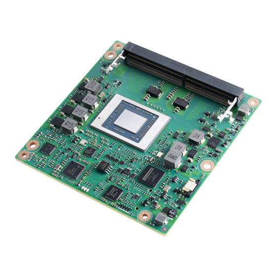
Page 25: Board Information
Board Information The figures below represent the main chips on the SOM-6872 Computer-on-Module. Please be aware of these positions when designing carrier boards to avoid mechani- cal problems. Use the thermal solution contacts for best thermal dissipation perfor- mance. DDR4 SODIMM Socket... -
Page 26: Connector List
Table 2.1: SFAN1 Fan SFAN1 Description Wafer 1 x 3P/1.25mm/(M)/NY46/RA/Sn/S/WH/H3.4mm Pin Name Fan Tach0-Input Fan Out Mechanical Diagram For more details about 2D/3D models, check out Advantech’s COM support service website http://com.advantech.com. Figure 2.3 Board mechanical diagram - front SOM-6872 User Manual... - Page 27 Figure 2.4 Board mechanical diagram - rear Figure 2.5 Board mechanical diagram - side SOM-6872 User Manual...
-
Page 28: Assembly Drawing
COM module to the carrier board. Figure 2.6 Assembly diagram There are 3 x reserved screw holes for SOM-6872 that are used in pre-assembling it with the heat spreader. Please consider the CPU and chip height tolerance when designing your thermal solution. - Page 29 SOM-6872 User Manual...
-
Page 30: Chapter 3 Ami Bios
Chapter AMI BIOS This chapter details BIOS setup information for the SOM-6872 CPU computer-on module. Sections include: Introduction Entering Setup Hot/Operation Key Exit BIOS Setup Utility... -
Page 31: Introduction
This information is stored in flash ROM so it retains the Setup information when the power is turned off. Entering Setup Turn on the computer and then press <DEL> or <ESC> to enter the Setup menu. SOM-6872 User Manual... -
Page 32: Main Setup
System Date using the <Arrow> keys. Enter new values through the keyboard. Press the <Tab> key or the <Arrow> keys to move between fields. The date must be entered in MM/DD/YY format. The time must be entered in HH:MM:SS format. SOM-6872 User Manual... -
Page 33: Advanced Bios Features Setup
Advanced BIOS Features Setup Select the Advanced tab from the SOM-6872 setup screen to enter the Advanced BIOS Setup screen. Users can select any item in the left frame of the screen, such as CPU Configuration, to go to the sub menu for that item. Users can display an Advanced BIOS Setup option by highlighting it using the <Arrow>... -
Page 34: Trusted Computing
Win8/Win10, TCG_2: Support new TCG2 protocol and event format for Win10 or later Physical Presence Spec Version Select to Tell O.S. to support PPI Spec Version 1.2 or 1.3. Note some HCK tests might not support 1.3. SOM-6872 User Manual... -
Page 35: Acpi Settings
OS. ACPI Sleep State Select the highest ACPI sleep state the system will enter when the SUSPEND button is pressed Lock Legacy Resources Enables or Disables Lock of Legacy Resources SOM-6872 User Manual... -
Page 36: Embedded Controller
Serial Port 2 Configuration Set Parameters of Serial Port 2 (COMB) Hardware Monitor Monitor hardware status ACPI Report Method Configuration Select ACPI Reporting Method for EC Devices CANBus Controller Enable/Disable CANBus controller on RDC-IS200 SOM-6872 User Manual... - Page 37 Figure 3.7 Serial port 1 configuration screen Serial Port Enable or Disable Serial Port (COM) Device Settings Set Parameters of Serial Port 1 (COMA) Change Settings Select an optimal settings for Super IO Device SOM-6872 User Manual...
- Page 38 Figure 3.8 Serial port 2 configuration screen Serial Port Enable or Disable Serial Port (COM) Device Settings Set Parameters of Serial Port 2 (COMB) Change Settings Select an optimal settings for Super IO Device SOM-6872 User Manual...
- Page 39 3.4.3.3 Hardware Monitor Figure 3.9 Hardware monitor screen SOM-6872 User Manual...
- Page 40 Exposed -> Reported vendor_HID(Driver installation is necessary) ACPI Report Method for I2C Bus Select the ACPI reporting method for EC I2C Bus. Hidden -> Reported as reserved motherboard resource. Exposed -> Reported vendor_HID(Driver installation is necessary) SOM-6872 User Manual...
-
Page 41: Serial Port Console Redirection
Console Redirection Enable or Disable. Console Redirection Settings The settings specify how the host computer and the remote computer (which the user is using) will exchange data. Both computers should have the same or compatible settings. SOM-6872 User Manual... - Page 42 Hardware flow control uses two wires to send start/stop signals VT-UTF8 Combo Key Support Enable VT-UTF8 combination key support for ANSI/VT100 terminals Recorder Mode With this mode enabled only text will be sent. This is to capture terminal data SOM-6872 User Manual...
-
Page 43: Cpu Configuration
Enable/Disable the generation of ACPI_PPC, _PSS and PCT objects PPC Adjustment Provide to adjust_PPC object NX Mode Enable/Disable no-execute page protection function SVM Mode Enable/Disable CPU virtualization Node 0 Information View Memory Information related to Node 0 SOM-6872 User Manual... - Page 44 Figure 3.14 Socket0 screen SOM-6872 User Manual...
-
Page 45: Sata Configuration
3.4.6 SATA Configuration Figure 3.15 SATA configuration screen SOM-6872 User Manual... -
Page 46: Usb Configuration
Maximum time the device will take before it properly reports itself to the Host Controller.'Auto' uses default value: for a Root port it is 100 ms, for a Hub port the delay is taken from Hub descriptor. JetFlashTranscend 8GB 1100 SOM-6872 User Manual... -
Page 47: Ami Rom Dispatch Policy
Slot #33 Empty Enable or disable option ROM execution for selected slot Slot #50 Empty Enable or disable option ROM execution for selected slot Slot #51 Empty Enable or disable option ROM execution for selected slot SOM-6872 User Manual... - Page 48 If system has SR-IOV capable PCIe devices, this option enables or disables sin- gle root IO virtualization support BHE DNA mitigation Re-enables bus master attribute disabled during Pci enumeration for PCI bridges after SMM locked SOM-6872 User Manual...
-
Page 49: Network Stack
3.4.9 Network Stack Figure 3.19 Network stack screen Network Stack Enable/Disable UEFI Network Stack 3.4.9.1 Network Stack Configuration Figure 3.20 Network stack screen SOM-6872 User Manual... -
Page 50: Nvme Configuration
Media detect count| Number of times presence of media will be checked. Use either +/- or numeric keys to set the value 3.4.10 NVMe Configuration Figure 3.21 NVMe configuration screen No NVNE Device Found SOM-6872 User Manual... -
Page 51: Amd Cbs
3.4.11 AMD CBS Figure 3.22 CPU Common options screen CPU Common Options CPU common options NBIO Common Options NBIO Common Options FCH Common Options FCH Common Options SOM-6872 User Manual... - Page 52 Core Performance Boost Disable CPB Global C-State Control Control IO based C-state generation and DF C-states. There is another DF Cstate option which will be synchronized with this option if DF Cstate option is auto SOM-6872 User Manual...
- Page 53 NBIO Common Options Figure 3.24 NBIO Common options screen IOMMU Enable/Disable IOMMU PCIe ARI Support Enable /Disable ARI PSPP Policy No help string Audio Configuration Audio Configuration SMU Common Options SMU Common Options SOM-6872 User Manual...
- Page 54 Audio Configuration Figure 3.25 Audio configuration screen NB Azalia Enable Integrate HD Audio Controller Audio IOs Audio IOs Control SOM-6872 User Manual...
- Page 55 SMU Common Options Figure 3.26 SMU Common options screen System Configuration Warning: Select system configuration may cause the system to hang, as some system configuration may not be supported by your OPN CPPC CPPC SOM-6872 User Manual...
- Page 56 CPPC Figure 3.27 CPPC screen CPPC CTRL CCPC Control: Enable-Override, Disable-Set default SOM-6872 User Manual...
- Page 57 FCH Common Options Figure 3.28 FCH Common options screen SATA Configuration Options SATA Configuration Options USB Configuration Options USB Configuration Options Ac Power Loss Options Ac Power Loss Options SOM-6872 User Manual...
- Page 58 SATA RAS Support Disable or enable SATA RAS support SATA Disable AHCI Prefetch Function Disable or enable SATA Disabled AHCI Prefetch Function Aggressive SATA Device Sleep Port0 No help string Aggressive SATA Device Sleep Port1 No help string SOM-6872 User Manual...
- Page 59 USB Configuration Options Figure 3.30 USB Configuration options screen xHCI0 controller enable Enable or disable USB3 controller xHCI1 controller enable Enable or disable USB3 controller Combo Phy Static Configuration Combo Phy Static Configuration SOM-6872 User Manual...
- Page 60 Combo PHY Static Configuration Figure 3.31 Combo PHY static configuration screen – Controller 0 Combo PHY Static Config No help string – Controller 1 Combo PHY Static Config No help string SOM-6872 User Manual...
- Page 61 Ac Power Loss Options Figure 3.32 Ac Power loss options screen Ac Loss Control Select Ac Loss Control Method SOM-6872 User Manual...
-
Page 62: Amd Pbs
DP1 Select Config Display port 1 to Display Port, HDMI or Disable Make on PME Determines the action taken when the system power is off and a PCI power management. Enable wake up event occurs. SOM-6872 User Manual... -
Page 63: Nic Configuration
3.4.13 NIC Configuration Figure 3.34 NIC configuration screen NIC configuration Click to configuration the network device port Blink LEDs Identify the physical network port by blinking the associated LED SOM-6872 User Manual... - Page 64 Figure 3.35 Link speed screen Link Speed Specifies the port speed used for the selected boot protocol Wake On Lan Enables the server to be powered on using an in-band magic paket SOM-6872 User Manual...
-
Page 65: Chipset Settings
Chipset Settings Select the chipset tab from the SOM-6872 setup screen to enter the chipset BIOS Setup screen. You can display a chipset BIOS setup option by highlighting it using the <Arrow> keys. All Plug and Play BIOS setup options are described in this section The Plug and Play BIOS Setup screen is shown below. - Page 66 3.5.1.1 SB USB Configuration Figure 3.37 SB USB Configuration screen SB USB Configuration Options For SB USB Configuration Figure 3.38 XHCI0/XHCI1 screen SOM-6872 User Manual...
-
Page 67: Nxp3460 Configuration
Color depth and packing format Select LCD panel Dual LVDS mode Dual LVDS mode LCD panel type Select LCD panel LVDS Clock spreading LVDS Clock spreading LVDS Swing level LVDS Swing level SOM-6872 User Manual... -
Page 68: North Bridge
3.5.3 North Bridge Figure 3.40 North bridge screen Total memory Total memory in the system Socket0 Information View information related to Socket0 SOM-6872 User Manual... -
Page 69: Pcie Lanes Configuration
3.5.3.1 Socket 0 Information Figure 3.41 Socket 0 information screen 3.5.4 PCIE Lanes Configuration Figure 3.42 PCIE Lanes Configuration screen SOM-6872 User Manual... - Page 70 NB root port ASPM Mode Control Hotplug Mode(Dev#2/Func#2) NB Root Port Hotplug Mode Control Device2Fun 3 Enable/Disable/Auto, Auto used board default setting ASPM mode(Dev#2/Func#3) NB root port ASPM Mode Control Hotplug Mode(Dev#2/Func#3) NB Root Port Hotplug Mode Control SOM-6872 User Manual...
-
Page 71: Security Settings
Security Settings Select Security Setup from the SOM-6872 Setup main BIOS setup menu. All Security Setup options, such as password protection is described in this section. To access the sub menu for the following items, select the item and press <Enter>: Figure 3.43 Security setting screen... -
Page 72: Secure Boot
Force system to user mode. Install factory default secure boot key databases Reset To Setup Mode Delete all secure boot key databases from NVRAM Key management Enables expert users to modify secure boot policy variables without full authen- tication SOM-6872 User Manual... -
Page 73: Vendor Keys
PE image into authorized signature database(db) Remove ‘UEFI CA’ from DB Device guard ready system must not list “Microsoft UEFI CA” certificate in authorized signature database(db) Restore DB defaults Restore DB variable to factory defaults SOM-6872 User Manual... -
Page 74: Boot Configuration
Enables or disables Quiet Boot option Boot Option Priorities Boot Option #1 Sets the system boot order Fast Boot Enable or Disable FastBoot features. Most probes are skipped to reduce time cost during boot. SOM-6872 User Manual... -
Page 75: Save & Exit
Restore Defaults Restore/Load Default values for all the setup options. Save as User Defaults Save the changes done so far as User Defaults. Restore User Defaults Restore the User Defaults to all the setup options. SOM-6872 User Manual... -
Page 76: Chapter 4 S/W Introduction And Installation
Chapter S/W Introduction and Installation S/W Introduction Driver Installation Advantech iManager... -
Page 77: S/W Introduction
4.2.1 Windows Driver Setup SOM-6872 supports Windows* 10 Enterprise. To install the drivers on a windows- based operation system, please connect to Internet and browse the website http:// support.advantech.com.tw and download the drivers that you want to install and fol- low Driver Setup instructions to complete the installation 4.2.2... -
Page 78: Advantech Imanager
It makes these embedded features easier to integrate, speed up develop- ing schedule, and provide the customer’s software continuity while upgrade hard- ware. More details of how to use the APIs and utilities, please refer to Advantech iManager 2.0 Software API User Manual. - Page 79 SOM-6872 User Manual...
-
Page 80: Appendix A Pin Assignment
Appendix Pin Assignment This appendix provides informa- tion regarding the SOM-6872 CPU System on Module hardware pin assignment. Sections include: SOM-6872 Type 6 Pin Assign- ment... -
Page 81: Som-6872 Type 6 Pin Assignment
SOM-6872 Type 6 Pin Assignment This section provides the SOM-6872 pin assignment on COM Express connector. This is compliant with COMR.0 R3.0 Type 6 pin-out definitions. For more details regarding the use of these pins and/or to acquire design reference, please contact Advantech. - Page 82 LVDS_A0+ LVDS_B0+ LVDS_A0- LVDS_B0- LVDS_A1+ LVDS_B1+ LVDS_A1- LVDS_B1- LVDS_A2+ LVDS_B2+ LVDS_A2- LVDS_B2- LVDS_VDD_EN LVDS_B3+ LVDS_A3+ LVDS_B3- LVDS_A3- LVDS_BKLT_EN GND (FIXED) GND (FIXED) LVDS_A_CK+ LVDS_B_CK+ LVDS_A_CK- LVDS_B_CK- LVDS_I2C_CK LVDS_BKLT_CTRL LVDS_I2C_DAT VCC_5V_SBY GPI3 VCC_5V_SBY VCC_5V_SBY eDP_HPD VCC_5V_SBY PCIE_CLK_REF+ BIOS_DIS1# SOM-6872 User Manual...
- Page 83 B110 GND (FIXED) SOM-6872 Row C,D GND (FIXED) GND (FIXED) USB_SSRX0- USB_SSTX0- USB_SSRX0+ USB_SSTX0+ USB_SSRX1- USB_SSTX1- USB_SSRX1+ USB_SSTX1+ GND (FIXED) GND (FIXED) DDI1_CTRLCLK_AUX+ DDI1_CTRLDATA_AUX- PCIE_RX6+ PCIE_TX6+ PCIE_RX6- PCIE_TX6- GND (FIXED) GND (FIXED) PCIE_RX7+ PCIE_TX7+ PCIE_RX7- PCIE_TX7- DDI1_HPD SOM-6872 User Manual...
- Page 84 PEG_RX0- PEG_TX0+ PEG_RX0- PEG_TX0- PEG_RX1+ PEG_TX1+ PEG_RX1- PEG_TX1- TYPE2# (GND) PEG_RX2+ PEG_TX2+ PEG_RX2- PEG_TX2- GND (FIXED) GND (FIXED) PEG_RX3+ PEG_TX3+ PEG_RX3- PEG_TX3- PEG_RX4+ PEG_TX4+ PEG_RX4- PEG_TX4- RAPID_SHUTDOWN PEG_RX5+ PEG_TX0+ PEG_RX5- PEG_TX0- GND(FIXED) GND(FIXED) PEG_RX6+ PEG_TX6+ PEG_RX6- PEG_TX6- SOM-6872 User Manual...
- Page 85 GND (FIXED) C101 D101 C102 D102 C103 D103 C104 VCC_12V D104 VCC_12V C105 VCC_12V D105 VCC_12V C106 VCC_12V D106 VCC_12V C107 VCC_12V D107 VCC_12V C108 VCC_12V D108 VCC_12V C109 VCC_12V D109 VCC_12V C110 GND (FIXED) D110 GND (FIXED) SOM-6872 User Manual...
-
Page 86: Appendix B Watchdog Timer
Appendix Watchdog Timer This appendix provides informa- tion regarding the watchdog timer programming for the SOM-6872 CPU System on Module. Sections include: Watchdog Timer Programming... -
Page 87: Programming The Watchdog Timer
** WDT new driver support automatically selects available IRQ number from BIOS, and then sets the EC. Only Windows 10 supports this feature. For other OS it uses the IRQ number from BIOS settings as usual. For details, please refer to iManager and/or the software API’s user manual. SOM-6872 User Manual... -
Page 88: Appendix C Programming Gpio
Appendix Programming GPIO This appendix details the General Purpose Input and Output pin set- tings Sections include: System I/O ports... -
Page 89: Gpio Register
GPIO Register GPIO Byte Mapping H/W Pin Name BIT0 GPO0 BIT1 GPO1 BIT2 GPO2 BIT3 GPO3 BIT4 GPI0 BIT5 GPI1 BIT6 GPI2 BIT7 GPI3 For details, please refer to iManager and Software API User Manual. SOM-6872 User Manual... -
Page 90: Appendix D System Assignments
Appendix System Assignments This appendix details the system resource allocation on the SOM- 6872 CPU System on Module. Sections include: System I/O ports DMA Channel Assignments Interrupt Assignments MB Memory Map 1... -
Page 91: System I/O Ports
Motherboard resources 0x00000065-0x00000065 Motherboard resources 0x00000067-0x0000006F Motherboard resources 0x00000072-0x0000007F Motherboard resources 0x00000080-0x00000080 Motherboard resources 0x00000084-0x00000086 Motherboard resources 0x00000088-0x00000088 Motherboard resources 0x0000008C-0x0000008E Motherboard resources 0x00000090-0x0000009F Motherboard resources 0x000000A2-0x000000BF Motherboard resources 0x000000B1-0x000000B1 Motherboard resources 0x000000E0-0x000000EF Motherboard resources 0x000004D0-0x000004D1 Motherboard resources SOM-6872 User Manual... -
Page 92: Interrupt Assignments
IRQ 36 High Definition Audio Controller IRQ 37 AMD Sensor Fusion Hub IRQ 39 AMD Audio CoProcessor IRQ 39 High Definition Audio Controller IRQ 1024 Trusted Platform Module 2.0 IRQ 4294967282 Intel® I210 Gigabit Network Connection #4 SOM-6872 User Manual... - Page 93 AMD USB 3.10 eXtensible Host Controller - 1.10 (Microsoft) IRQ 4294967260 AMD PSP 10.0 Device IRQ 4294967259 AMD PSP 10.0 Device IRQ 4294967293 PCI Express Root Port IRQ 4294967292 PCI Express Root Port IRQ 4294967294 PCI Express Root Port SOM-6872 User Manual...
-
Page 94: 1St Mb Memory Map
PCI Express Root Port 0xFE8B0000-0xFE8B1FFF AMD Sensor Fusion Hub 0xFE8B8000-0xFE8BFFFF High Definition Audio Controller 0xFEDC2000-0xFEDC2FFF AMD I2C Controller 0xFEC00000-0xFEC00FFF Motherboard resources 0xFEC01000-0xFEC01FFF Motherboard resources 0xFEDC0000-0xFEDC0FFF Motherboard resources 0xFED80000-0xFED8FFFF Motherboard resources 0xFEC10000-0xFEC10FFF Motherboard resources 0xFF000000-0xFFFFFFFF Motherboard resources 0xFD000000-0xFDFFFFFF Motherboard resources SOM-6872 User Manual... - Page 95 No part of this publication may be reproduced in any form or by any means, electronic, photocopying, recording or otherwise, without prior written permis- sion from the publisher. All brand and product names are trademarks or registered trademarks of their respective companies. © Advantech Co., Ltd. 2021...
Need help?
Do you have a question about the SOM-6872 and is the answer not in the manual?
Questions and answers