Table of Contents
Advertisement
Quick Links
Advertisement
Table of Contents

Related Manuals for Advantech ARK-1125


Summary of Contents for Advantech ARK-1125
- Page 1 User Manual ARK-1125 Fanless Embedded Box PC...
- Page 2 Veuillez noter que ce paquet contient un manuel d'utilisation papier en chinois à des fins de certification China CCC. Veuillez ne pas tenir compte du manuel d'utilisation chinois sur papier si le produit ne doit pas être vendu et/ou installé en Chine. ARK-1125 User Manual...
- Page 3 No part of this manual may be reproduced, copied, translated, or transmitted in any form or by any means without the prior written permission of Advantech Co., Ltd. The information provided in this manual is intended to be accurate and reliable.
-
Page 4: Product Warranty (2 Years)
Product Warranty (2 Years) Advantech warrants the original purchaser that each of its products will be free from defects in materials and workmanship for two years from the date of purchase. This warranty does not apply to any products that have been repaired or altered by persons other than repair personnel authorized by Advantech, or products that have been subject to misuse, abuse, accident, or improper installation. -
Page 5: Technical Support And Assistance
Technical Support and Assistance Visit the Advantech website at http://support.advantech.comto obtain the latest product information. Contact your distributor, sales representative, or Advantech's customer service center for technical support if you need additional assistance. Please have the following information ready before calling: –... -
Page 6: Ordering Information
The equipment shows obvious signs of breakage. Do not leave the equipment in an environment with a storage temperature of below -40°C (-40°F) or above 85°C (185°F) as this may damage the compo- nents. The equipment should be kept in a controlled environment. ARK-1125 User Manual... -
Page 7: Consignes De Sécurité
70 dB (A). DISCLAIMER: These instructions are provided according to IEC 704-1 specifi- cations. Advantech disclaims all responsibility for the accuracy of any state- ments contained herein. Use a power cord connected to a socket-outlet with a grounded connection. - Page 8 Ce produit est destiné à être alimenté par une alimentation homologuée UL adaptée à une utilisation à une température minimale de Tma de 60°C (140°F) dont la sortie est nominale de 12 Vcc, 5 A. Veuillez contacter Advantech pour plus d'informations.
-
Page 9: Table Of Contents
Table 2.5: JPSON1 AT/ATX Mode Jumper ....... 13 Connectors....................14 2.3.1 ARK-1125 External I/O Locations ..........14 Figure 2.3 ARK-1125H Front and Rear I/O Connector Diagram14 Figure 2.4 ARK-1125C Front and Rear I/O Connector Diagram14 Figure 2.5 Power On/Off Button ..........14 Figure 2.6 Power Input Connector.......... - Page 10 BIOS Settings ........29 Introduction ..................... 30 Entering BIOS Setup................30 3.2.1 Main Setup.................. 30 3.2.2 Advanced Setup ................. 32 3.2.3 Chipset Configuration ..............81 3.2.4 Security..................101 3.2.5 Boot ..................103 3.2.6 Save & Exit ................104 ARK-1125 User Manual...
-
Page 11: Chapter 1 General Introduction
Chapter General Introduction This chapter details background information on the ARK-1125 series. -
Page 12: Introduction
Rugged Multi-Functional Design The ARK-1125 is powered by an Intel® N200 QC SoC processor or an Intel® Atom™ x7211E DC SoC processor to offer high performance with low power consumption. Its palm-sized dimensions allow it to be installed in limited-space environments. The ARK-1125 provides a selection of I/O ports for different applications, depending on the model. -
Page 13: Product Features
ARK-1125C: 1 x HDMI 1.2.3 Ethernet Chipset: – ARK-1125H: LAN1 Intel® i226-LM, LAN2 Intel® i226-LM – ARK-1125C: LAN1 Intel® i226-LM Speed: 100/1000/2500 Mbps Interface: RJ-45 Standard: Compliant with IEEE 802.3, IEEE 802.3u, IEEE 802.3bz, IEEE 802.ab ARK-1125 User Manual... -
Page 14: Chipset
ARK-1125C supports 1 signal within one CAN Bus port. GPIO: 8-bit Programmable DIO Ethernet: – Chipset: Intel® i226 LM, – ARK-1125H supports 2 x LAN ports, ARK-1125C supports 1 x LAN port – ARK-1125H: LAN1, LAN2 – ARK-1125C: LAN1 – Supports 2.5GbE ARK-1125 User Manual... -
Page 15: Susi 4.0
System information running HR / boot record Mechanical Specifications 1.4.1 ARK-1125H Dimensions 133 x 46.4 x 94.2 mm / 5.24 x 1.83 x 3.71 in (W x H x D) Figure 1.1 ARK-1125H Mechanical Dimensions ARK-1125 User Manual... -
Page 16: Ark-1125C Dimensions
Adapter: 60W @ 12V/5A power adapter Operating Environment Specifications 1.6.1 Operating Temperature With extended peripherals: -30 ~ 60°C (-22 ~ 140°F) with 0.7 m/s airflow (only up to 40°C when used with the adapter) ARK-1125 User Manual... -
Page 17: Relative Humidity
1.6.2 Relative Humidity 95% @ 40°C (104°F) (non-condensing) 1.6.3 Storage Temperature -40 ~ 85°C (-40 ~ 185°F) 1.6.4 CE/FCC Class B, CCC, BSMI, UKCA 1.6.5 Safety CB, UL, CCC, BSMI, UKCA ARK-1125 User Manual... - Page 18 ARK-1125 User Manual...
-
Page 19: Chapter 2 Configuration
Chapter Configuration... -
Page 20: Introduction
2.2.1 Jumper Description You may configure ARK-1125 to match the needs of your application by setting jump- ers. A jumper is a metal bridge used to close an electric circuit. It consists of two metal pins and a small metal clip (often protected by a plastic cover) that slides over the pins to connect them. -
Page 21: Jumper Locations
2.2.3 Jumper Locations Figure 2.1 ARK-1125H Jumper Locations Figure 2.2 ARK-1125C Jumper Locations ARK-1125 User Manual... -
Page 22: Jumper Settings
Table 2.3: M2_SEL1 M.2 B-Key Device Selection Part Number 1653006615-01 Footprint HD_4x1P_50_D_21N10240-04S10B Description PIN HEADER 1x4P 27mm/PA6T/M/VA/GFL/D/BK/H2.0mm/L2.6 Setting Function (1-2 Closed) SSD (default) (1-2 Open) WWAN Card (3-4 Closed) SSD – SATA type (3-4 Open) SSD – PCIE type (default) ARK-1125 User Manual... - Page 23 ERP mode 2.2.4.4 HW AT/ATX Mode Jumper (JPSON1) Table 2.5: JPSON1 AT/ATX Mode Jumper Part Number 1653004101 Footprint HD_4x1P_79_D Description PIN HEADER 4x1P 2.0mm 180D(M) DIP 21N12050 Setting Function (1-2 Closed) ATX Mode (default) (3-4 Closed) AT Mode ARK-1125 User Manual...
-
Page 24: Connectors
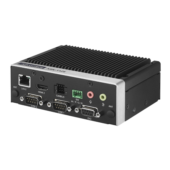
Figure 2.4 ARK-1125C Front and Rear I/O Connector Diagram 2.3.1.3 Power On/Off Button ARK-1125 has a Power On/Off button with LED indicators that show the On status (Green LED). The Power button supports dual functions: Soft instant Power On/-Off. Figure 2.5 Power On/Off Button 2.3.1.4... - Page 25 2.3.1.5 M.2 B-Key LED Indicator ARK-1125 provides one LED that indicates M.2 B-Key and compact flash disk status. Figure 2.7 HDD LED Indicator 2.3.1.6 Antenna Hole ARK-1125 reserves 4 antenna holes for wireless antenna installation. Each antenna hole is marked “ANT” for easy identification.
- Page 26 2.3.1.8 DIO Connector ARK-1125 provides 1 x DIO connector. Figure 2.10 DIO Connector Table 2.6: DIO Connector Pin Definitions Signal Name DIO bit 0 DIO bit 1 DIO bit 2 DIO bit 3 DIO bit 4 DIO bit 5 DIO bit 6...
- Page 27 2.3.1.9 COM Connector ARK-1125 provides 2 x D-sub 9-pin connectors on ARK-1125H and 4 on ARK-1125C, which offer RS-232/422/485 serial communication interface ports. The default setting is RS-232. RS-422/485 for ARK-1125 are supported via the BIOS settings. Figure 2.11 DIO Connector Table 2.7: COM Connector Pin Definitions...
- Page 28 2.3.1.10 Ethernet Connector (LAN) ARK-1125 is equipped with 2 x Ethernet controllers on ARK-1125H and 1 on ARK- 1125C that are fully compliant with IEEE 802.3u 100/1000/2500 Mbps. These Ether- net ports provide a standard RJ-45 jack connector with LED indicators. The left side LED shows link status (Green LED) and active status (flashing Green LED), and the right side LED shows Speed status (Green LED for 2.5Gbps/Orange LED for 1Gbps).
- Page 29 2.3.1.12 USB 3.2 - Gen 2 ARK-1125 supports 2 x USB 3.2 (Gen 2, 10G), The USB interfaces comply with USB XHCI, Rev. 3.2 standards. USB 3.2 Gen2 connectors contain legacy pins to interface with USB 2.0 devices, and a new set of pins for USB 3.2 connectivity.
- Page 30 Table 2.11: Ethernet Connector (LAN) Pin Definitions Signal Name 2.3.1.14 Remote Switch Connector ARK-1125 provides the remote switch connector for power on/off. From the left to the right are WDT, Power Switch, GND, and Reset. Figure 2.16 Remote Switch Connector ARK-1125 User Manual...
- Page 31 Table 2.12: Ethernet Connector (LAN) Pin Definitions Signal Name CAN0_D- CAN1_D+ CAN0_D+ CAN1_D- Note! NC represents “No Connection”. 2.3.1.16 CAN Bus ARK-1125C provides an optional CAN bus connector. Table 2.13: CAN Bus Connector Pin Definitions Signal Name Signal Name CAN_L CAN_H ARK-1125 User Manual...
-
Page 32: Installation
Installation 2.4.1 Memory Installation ARK-1125H and ARK-1125C share the same installation method. Unscrew the 4 screws on the top cover, and remove the top cover. Install the memory into the system carefully. Replace the top cover. ARK-1125 User Manual... -
Page 33: Module Installation
DIO port, and remove the DIO cable first. Then replace the DIO cable after the module is installed. 2.4.2.1 ARK-1125H ARK-1125H provides 2 options for SSD: 1x M.2 2230 E-Key (PCIe x1) and 1 x M.2 2280 B-Key (SATA, PCIe x1). ARK-1125 User Manual... - Page 34 2.4.2.2 ARK-1125C ARK-1125C provides 3 options for SSD: 1 x M.2 2230 E-Key (PCIe x1), 1 x M.2 2280 B-Key (SATA, PCIe x1), and 1x M.2 2242 M-Key (SATA, PCIe x1). ARK-1125 User Manual...
-
Page 35: Wall Mount Installation
Wall Mount Installation Unscrew the 4 x M3x5L screws on the side. Install the wall mount brackets with the same screws. Dévissez les 4 vis M3x5L sur le côté Installez les pièces du support mural avec les mêmes vis. ARK-1125 User Manual... -
Page 36: Optional Can Bus Installation
2.4.4 Optional CAN Bus Installation Unscrew the 4 x M3x5L screws on the side and remove the bottom cover. Unscrew the 2 screws for the DIO port, and remove the DIO cable. ARK-1125 User Manual... - Page 37 Connect the CAN bus cable, and replace the bottom cover. ARK-1125 User Manual...
- Page 38 ARK-1125 User Manual...
-
Page 39: Chapter 3 Bios Settings
Chapter BIOS Settings This chapter details instructions for setting BIOS configuration data. -
Page 40: Introduction
All configuration data is stored in battery-backed CMOS to ensure the setup information is retained when the power is turned off. This chapter describes the basic navigation of the ARK-1125 BIOS setup screens. - Page 41 System Time using the <Arrow> keys. Enter new values via the keyboard. Press the <Tab> key or the <Arrow> keys to move between fields. The date must be entered in MM/DD/YY format, and the time must be entered in HH:MM:SS for- mat. ARK-1125 User Manual...
-
Page 42: Advanced Setup
The options for any of the Advanced BIOS Setup items can be displayed by highlighting the item using the <Arrow> keys. The Advanced BIOS Setup page is shown below: ARK-1125 User Manual... - Page 43 3.2.2.1 WWAN Configuration WWAN Configuration WWAN Device Enable/Disable M.2 WWAN Device. 3.2.2.2 CPU Configuration ARK-1125 User Manual...
- Page 44 Efficient-core Information Displays the Efficient-core Information. Performance-core Information Displays the P-core Information. ARK-1125 User Manual...
- Page 45 AP threads Idle Manner for waiting signal to run. Enable/Disable AES. (Advanced Encryption Standard) MachineCheck Enable/Disable Machine Check. MonitorMWait Enable/Disable MonitorMWait. If Disabled, the AP threads Idle Manner should not be set to MWAIT Loop. ARK-1125 User Manual...
- Page 46 Efficient-core Information ARK-1125 User Manual...
- Page 47 CPU SMM Enhancement SMM Use Delay Indication – Enable/Disable usage of SMM_DELAYED MSR for MP sync in SMI. – SMM Use Block Indication Enable/Disable usage of SMM_BLOCKED MSR for MP sync in SMI. ARK-1125 User Manual...
- Page 48 – SMM Use SMM en-US Indication Enable/Disable usage of SMM_ENABLE MSR for MP sync in SMI. 3.2.2.3 Power & Performance – CPU Power Management Control CPU - Power Management Control ARK-1125 User Manual...
- Page 49 Select the performance state that the BIOS will set before OS hand-off. – Intel® Speedstep™ Allows more than two frequency ranges to be supported. – Race to Halt (RTH) Enable/Disable Race To Halt feature. RTH will dynamically increase CPU fre- ARK-1125 User Manual...
- Page 50 – Interrupt Redirection Mode Selection Interrupt Redirection Mode Select for Logical Interrupts. – Timed MWAIT Enable/Disable Timed MWAIT Support. – EC Turbo Control Mode Enable/Disable EC Turbo Control mode. – Energy Performance Gain Enable/disable Energy Performance Gain. ARK-1125 User Manual...
- Page 51 Turbo Ratio Limit Options Energy Efficient P-state – Enable/Disable Energy Efficient P-state feature. – Package Power Limit MSR Lock Enable/Disable locking of Package Power Limit settings. ARK-1125 User Manual...
- Page 52 Power Limit 1 Override Enable/Disable Power Limit 1 override. – Power Limit 2 Override Enable/Disable Power Limit 2 override. – Energy Efficient Turbo Enable/Disable Energy Efficient Turbo Feature. This feature will opportunisti- cally lower the turbo frequency to increase efficiency. ARK-1125 User Manual...
- Page 53 CPU VR Settings PSYS Slope – PSYS Slope defined in 1/100 increments. Range is 0-200. For a 1.25 slope, enter 125. 0 = AUTO. Uses BIOS VR mailbox command 0x9. ARK-1125 User Manual...
- Page 54 A value of AUTO(0) will use the board ID to determine the board design. Any other value will override the board ID logic to provide a custom VR Power Delivery Design value. This is intended primarily for vali- dation. ARK-1125 User Manual...
- Page 55 Enabling this option will help mitigate acoustic noise on certain SKUs when the CPU is in a deeper C state. – Pre Wake time Set the maximum Pre Wake randomization time in micro ticks. The range is ARK-1125 User Manual...
- Page 56 Set VR GT Slow Slew Rate for Deep Package C State ramp time; Slow slew rate is equal to Fast divided by number; the number is 2, 4, 8 to slow down the slew rate to help minimize acoustic noise; divide by 16 is disabled. Core/IA VR Settings ARK-1125 User Manual...
- Page 57 – VR Config Enable VR Config Enable. PS3 Enable – PS3 Enable/Disable. 0 - Disabled, 1 - Enabled. Uses BIOS VR mailbox com- mand 0x3. ARK-1125 User Manual...
- Page 58 TDC Time Window VR TDC Time Window, value in seconds. 1s is default. Range from 1s to 448s. TDC Lock – Enable/Disable TDC Lock. – IRMS Enable/Disable IRMS - Current root mean square. GT VR Settings ARK-1125 User Manual...
- Page 59 – VR Config Enable VR Config Enable. PS3 Enable – PS3 Enable/Disable. 0 - Disabled, 1 - Enabled. Uses BIOS VR mailbox com- mand 0x3. ARK-1125 User Manual...
- Page 60 TDC Enable – TDC Enable. 0- Disable, 1 – Enable – TDC Time Window VR TDC Time Window, value in seconds. 1s is default. Range from 1s to 448s. TDC Lock – Enable/Disable TDC Lock. RFI Settings ARK-1125 User Manual...
- Page 61 – FIVR Spread Spectrum Enable or Disable the FIVR Spread Spectrum. – RFI Spread Spectrum Set the Spread Spectrum. Custom P-state Table ARK-1125 User Manual...
- Page 62 – Number of P states Sets the number of custom P-states. At least 2 states must be present. Power Limit 3 Settings ARK-1125 User Manual...
- Page 63 – Power Limit 3 Override Enable/Disable Power Limit 3 override. CPU Lock Configuration ARK-1125 User Manual...
- Page 64 – CFG Lock Configure MSR 0xE2[15], CFG Lock bit. – Overclocking Lock Enable/Disable Overclocking Lock (BIT 20) in FLEX_RATIO(194) MSR. GT - Power Management Control ARK-1125 User Manual...
- Page 65 RC6 (Render Standby) Check to enable render standby support. – Maximum GT frequency Maximum GT frequency limited by the user. – Disable Turbo GT frequency Enabled: Disables Turbo GT frequency. Disabled: GT frequency is not lim- ited. ARK-1125 User Manual...
- Page 66 3.2.2.4 PCH-FW Configuration ME State When Disabled, ME will be put into ME Temporarily Disabled Mode. ME Unconfig on RTC Clear When Disabled, ME will not be unconfigured on RTC Clear. ARK-1125 User Manual...
- Page 67 Firmware Update Configuration – ME FW Image Re-Flash Enable/Disable ME FW Image Re-Flash function. FW Update – Enable/Disable ME FW Update function. ARK-1125 User Manual...
- Page 68 PTT Configuration – TPM Device Selection Configure TPM device. ARK-1125 User Manual...
- Page 69 OEM Key Revocation Configuration – Automatic OEM Key Revocation When enabled, the BIOS will automatically send an HECI command to revoke OEM keys. – Invoke OEM Key Revocation An HECI command will be send to revoke the OEM key. ARK-1125 User Manual...
- Page 70 – Extend CSME Measurement to TPM-PCR Enable/Disable Extend CSME Measurement to TPM-PCR[0] and AMT Con- fig to TPM-PCR[1]. 3.2.2.5 ACPI Setting ARK-1125 User Manual...
- Page 71 Enables/Disable BIOS ACPI Auto Configuration. Enable Hibernation Enable/Disable the system’s ability to hibernate (OS/S4 Sleep State). ACPI Sleep State Select the highest ACPI sleep state the system will enter when the SUSPEND button is pressed. 3.2.2.6 iManager Configuration ARK-1125 User Manual...
- Page 72 ARK-1125H ARK-1125C ARK-1125 User Manual...
- Page 73 Serial Port 1 Configuration – Serial Port Enable/Disable serial port. – Change Settings Select optimal settings for a Super IO device. – COM port mode COM Port Mode Select. ARK-1125 User Manual...
- Page 74 Serial Port 2 Configuration – Serial Port Enable/Disable serial port. Change Settings – Select optimal settings for a Super IO device. ARK-1125 User Manual...
- Page 75 – COM port mode COM Port Mode Select. Serial Port 3 Configuration – Serial Port Enable/Disable serial port. ARK-1125 User Manual...
- Page 76 – Change Settings Select optimal settings for a Super IO device. – COM port mode COM Port Mode Select. Serial Port 4 Configuration ARK-1125 User Manual...
- Page 77 – Serial Port Enable/Disable serial port. – Change Settings Select optimal settings for a Super IO device. – COM port mode COM Port Mode Select. Hardware Monitor Provides hardware monitoring information. ARK-1125 User Manual...
- Page 78 Watch Dog Timer Configuration ARK-1125 User Manual...
- Page 79 – Watch Dog Timer Hidden Enable/Disable Watch Dog Timer Hidden. – Watch Dog Timer Enable/Disable the Watch Dog Timer function. GPIO Configuration ARK-1125 User Manual...
- Page 80 – GPIO Control Enable Select to control GPIO by EC or user override during the POST stage. ACPI Report Method Configuration ARK-1125 User Manual...
- Page 81 – ACPI Report Method Control Select ACPI Reporting Method for EC Devices. Default -> For most ACPI OS; Custom -> For 3rd Party Driver installation. 3.2.2.7 Trusted Computing ARK-1125 User Manual...
- Page 82 TPM 1.2 will restrict support to TPM 1.2 devices; TPM 2.0 will restrict support to TPM 2.0 devices; Auto will support both with the default set to TPM 2.0 devices if not found; TPM 1.2 devices will be enumerated. ARK-1125 User Manual...
- Page 83 3.2.2.8 S5 RTC Wake Settings Wake system from S5 Enable/Disable system wake on alarm event. ARK-1125 User Manual...
- Page 84 3.2.2.9 Serial Port Console Redirection Console Redirection Console Redirection Enable or Disable. Legacy Console Redirection Settings Legacy Console Redirection Settings. ARK-1125 User Manual...
- Page 85 Console Redirection EMS Console Redirection Enable or Disable. Legacy Console Redirection Settings – Redirection COM Port Select redirection COM port number. ARK-1125 User Manual...
- Page 86 When Bootloader is selected, then Legacy Console Redirection is disabled before booting to legacy OS. When Always Enable is selected, then Legacy Console Redirection is enabled for legacy OS. Default setting for this option is set to Always Enable. 3.2.2.10 USB Configuration ARK-1125 User Manual...
- Page 87 The time-out value for control, bulk, and interrupt transfers. Device Reset time-out USB mass storage device Start Unit command time-out. Device power-up delay Maximum time the device will take before it properly reports itself to the Host Controller. ARK-1125 User Manual...
- Page 88 3.2.2.11 Network Stack Configuration Network Stack Enable/Disable UEFI Network Stack. ARK-1125 User Manual...
- Page 89 3.2.2.12 CSM Configuration CSM Support Enable/Disable CSM Support. ARK-1125 User Manual...
- Page 90 3.2.2.13 NCMe Configuration ARK-1125 User Manual...
-
Page 91: Chipset Configuration
3.2.3 Chipset Configuration Select the Chipset tab from the ARK-1125 setup screen to enter the Chipset BIOS Setup screen. You can display a Chipset BIOS Setup option by highlighting it using the <Arrow> keys. All Plug-and-Play BIOS Setup options are described in this sec- tion. - Page 92 VT-d VT-d capability. Control Iommu Pre-boot Behavior Above 4GB MMIO BIOS assignment Enable/Disable above 4GB Memory Mapped I/O BIOS assignment. This is enabled automatically when the Aperture Size is set to 2048MB. ARK-1125 User Manual...
- Page 93 Memory Configuration – SAM Overloading Enable/Disable SAM Overloading. Graphics Configuration ARK-1125 User Manual...
- Page 94 Enable/Disable GT configuration in BIOS. RC1p Support – Enable/Disable RC1p support. If RC1p is enabled, send a RC1p frequency request to PMA based on other conditions being met. – PAVP Enable Enable/Disable PAVP. – Cdynmax Clamping Enable Enable/Disable Cdynmax Clamping. ARK-1125 User Manual...
- Page 95 Select the highest Cd Clock frequency supported by the platform. – Enable Display Audio Link in Pre-OS Enable: Display Audio Link will be enabled in Pre-OS. Disabled: Display Audio Link will be disabled in Pre-OS. DMI/OPI Configuration ARK-1125 User Manual...
- Page 96 – CDR Relock for CPU DMI Enable/Disable CDR Relock. – DMI ASPM DMI ASPM Support. DMI Gen3 L1 Latency – DMI Gen3 L1 Exit Latency. – New FOM for CPU DMI Enable/Disable New FOM. ARK-1125 User Manual...
- Page 97 DMI Advanced Menu ARK-1125 User Manual...
- Page 98 3.2.3.2 PCI-IO Configuration ARK-1125 User Manual...
- Page 99 ARK-1125H ARK-1125C Onboard LAN1~2 Controller Enable/Disable onboard NIC. PCIE Wake Enable or disable PCIE to wake the system from S5. ARK-1125 User Manual...
- Page 100 This is a tradeoff between power and IO latency. Flash Protection Range Registers (FPRR) Enable Flash Protection Range Registers. SPD Write Disable Enable/Disable setting SPD Write Disable. For security recommendations, SPD write disable bit must be set. PCI Express Configuration ARK-1125H ARK-1125 User Manual...
- Page 101 ARK-1125C – DMI Link ASPM Control The control of Active State Power Management of the DMI Link. – PCIe function swap Enable/Disable PCIe function swap. PCIe EQ settings ARK-1125 User Manual...
- Page 102 – PCIe EQ override Choose your own PCIe EQ settings, only for users who have a thorough understanding of the equalization process. M.2 E-Key ARK-1125 User Manual...
- Page 103 ASPM Set the ASPM Level: Force L0s - Force all links to L0s State. AUTO - BIOS auto configure. DISABLE - Disables ASPM. L1 Substates – PCI Express L1 Substates settings. – PCIe Speed Configure PCIe Speed. ARK-1125 User Manual...
- Page 104 M.2 B-Key ASPM – Set the ASPM Level: Force L0s - Force all links to L0s State. AUTO - BIOS auto configure. DISABLE - Disables ASPM – L1 Substates PCI Express L1 Substates settings. ARK-1125 User Manual...
- Page 105 – PCIe Speed Configure PCIe Speed. M.2 M-Key – ASPM Set the ASPM Level: Force L0s - Force all links to L0s State. AUTO - BIOS auto configure. DISABLE - Disables ASPM ARK-1125 User Manual...
- Page 106 – L1 Substates PCI Express L1 Substates settings. – PCIe Speed Configure PCIe Speed. SATA Configuration ARK-1125H ARK-1125 User Manual...
- Page 107 Enable/Disable SATA Port 1~2 DevSlp. For DevSlp to work, both the hard drive and SATA port need to support the DevSlp function; otherwise an unex- pected behavior might happen. Please check the board design before enabling it. ARK-1125 User Manual...
- Page 108 – Select 'Enabled' to enable SUS Well PG for USB2 PHY. This option has no effect on PCH-H – USB Port Disable Override Selectively Enable/Disable the corresponding USB port from reporting a Device Connection to the controller. ARK-1125 User Manual...
- Page 109 RTC Memory Lock – Enable will lock bytes 38h-3Fh in the lower/upper 128-byte bank of RTC RAM. – BIOS Lock Enable/Disable the PCH BIOS Lock Enable feature. It is required to be enabled to ensure SMM protection of flash. ARK-1125 User Manual...
- Page 110 – Force unlock on all GPIO pads If Enabled, the BIOS will force all GPIO pads to be in the unlocked state. HD Audio Configuration – HD Audio Control Detection of the HD-Audio device. ARK-1125 User Manual...
-
Page 111: Security
3.2.4 Security Administrator Password Set the Administrator Password. User Password Set the User Password. ARK-1125 User Manual... - Page 112 The Secure Boot feature is Active if Secure Boot is Enabled, Platform Key (PK) is enrolled, and the System is in User mode. The mode change requires a platform reset. – Secure Boot Mode Secure Boot mode options: Standard or Custom. ARK-1125 User Manual...
-
Page 113: Boot
3.2.5 Boot Setup Prompt Timeout Number of seconds to wait for setup activation key. 65535 (0xFFFF) means indefinite waiting. Bootup NumLock State Select the keyboard NumLock state. Quiet Boot Enable/Disable the Quiet Boot option. ARK-1125 User Manual... -
Page 114: Save & Exit
Restore Defaults Restore/Load Default values for all the setup options. Save as User Defaults Save the changes done so far as User Defaults. Restore User Defaults Restore the User Defaults to all the setup options. ARK-1125 User Manual... - Page 115 ARK-1125 User Manual...
- Page 116 No part of this publication may be reproduced in any form or by any means, such as electronically, by photocopying, recording, or otherwise, without prior written permission from the publisher. All brand and product names are trademarks or registered trademarks of their respective companies. © Advantech Co., Ltd. 2024...
Need help?
Do you have a question about the ARK-1125 and is the answer not in the manual?
Questions and answers