
Related Manuals for ADLINK Technology NuPRO-A301


Summary of Contents for ADLINK Technology NuPRO-A301
- Page 1 NuPRO-A301 Full-Sized PICMG 1.0 SBC Intel® 945GC/ICH7 Chipset User’s Manual Manual Rev.: 2.00 Revision Date: January 19, 2010 Part No: 50-13065-1000 Advance Technologies; Automate the World.
- Page 2 Revision History Revision Release Date Description of Change(s) 2.00 2010/01/19 Initial Release...
-
Page 3: Preface
NuPRO-A301 Preface Copyright 2010 ADLINK Technology Inc. This document contains proprietary information protected by copy- right. All rights are reserved. No part of this manual may be repro- duced by any mechanical, electronic, or other means in any form without prior written permission of the manufacturer. - Page 4 Using this Manual Audience and Scope The NuPRO-A301 User’s Manual is intended for hardware technicians and systems operators with knowledge of installing, configuring and operating industrial grade single board computers. Manual Organization This manual is organized as follows: Preface: Presents important copyright notifications, disclaimers, trademarks, and associated information on the proper understand- ing and usage of this document and its associated product(s).
- Page 5 NuPRO-A301 Conventions Take note of the following conventions used throughout this manual to make sure that users perform certain tasks and instructions properly. Additional information, aids, and tips that help users perform tasks. NOTE: NOTE: Information to prevent minor physical injury, component dam- age, data loss, and/or program corruption when trying to com- plete a task.
- Page 6 This page intentionally left blank. Preface...
-
Page 7: Table Of Contents
NuPRO-A301 Table of Contents Revision History..............ii Preface ..................iii List of Figures ................ ix List of Tables................xi 1 Introduction ................ 1 Overview................1 Features................1 Specifications............... 2 Mechanical Drawing ............4 Block Diagram ..............5 2 Hardware Information ............7 Rear Panel I/O Ports............ - Page 8 ISA Driver................35 Audio Driver ............... 36 5 BIOS Setup ................ 37 Starting the BIOS ............... 37 Standard CMOS Features ..........39 Advanced BIOS Features ..........43 Advanced Chipset Features..........46 Integrated Peripherals............48 Power Management Setup ..........53 PnP/PCI Configurations ............. 55 PC health Status ..............
-
Page 9: List Of Figures
NuPRO-A301 List of Figures Figure 1-1: NuPRO-A301 Board Dimensions (top view)....4 Figure 1-2: NuPRO-A301 Block Diagram .......... 5 Figure 2-1: Rear Panel I/O Ports............7 Figure 2-2: Connectors and Jumpers Pt. 1 ........10 Figure 2-3: Connectors and Jumpers Pt. 2 ........11... - Page 10 This page intentionally left blank. List of Figures...
-
Page 11: List Of Tables
NuPRO-A301 List of Tables Table B-1: Memory Map..............61 Table B-2: Direct Memory Access Channels........61 Table B-3: IO Map ................63 Table B-4: IRQ Map ................ 63 Table B-5: PCI Interrupt Routing Map ..........64 List of Tables... - Page 12 This page intentionally left blank. List of Tables...
-
Page 13: Introduction
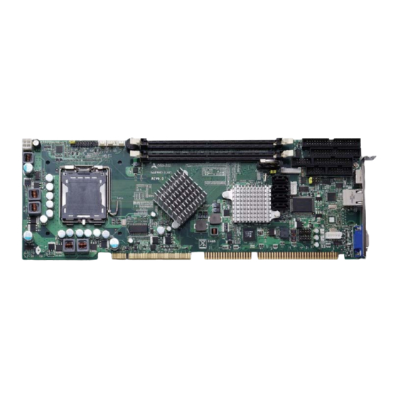
NuPRO-A301 Introduction 1.1 Overview The ADLINK NuPRO-A301 is a PICMG 1.0 industrial SBC sup- porting Intel® Core™2 Duo, Pentium® Dual Core, Pentium® 4, and Celeron® processors in the LGA775 package to deliver a high performance platform for a wide array of industrial automation applications. -
Page 14: Specifications
1.3 Specifications System • Intel® Core™2 Duo E4300, 1.8GHz, 800MHz FSB, 2MB L2 Cache, 65nm, 65W • Intel® Pentium® Dual Core E2160, 1.8GHz, 800MHz FSB, 1MB L2 Cache, 65nm, 65W • Intel® Celeron® 440, 2.0GHz, 800MHz FSB, 512KB L2 Cache, 65nm, 35W •... - Page 15 NuPRO-A301 Display • GMA 950 integrated in 945GC GMCH VRAM • Shared system memory up to 224 MB • External Dsub-15 connector, resolution up to 2048 x 1536 @ 75 Hz Ethernet • Intel® 82574L PCIe network controller, supports Controller...
-
Page 16: Mechanical Drawing
1.4 Mechanical Drawing Figure 1-1: NuPRO-A301 Board Dimensions (top view) Introduction... -
Page 17: Block Diagram
PCI slots to PCI Bus Controll golden finger AC97 Codec USB 2.0 x4 IT8888 ISA to golden ISA Bridge finger BIOS FWH Header for Daughter Board KB/Mouse W83627DHG LPC Super I/O Hardware COM1 Monitor COM2 Figure 1-2: NuPRO-A301 Block Diagram Introduction... - Page 18 This page intentionally left blank. Introduction...
-
Page 19: Hardware Information
NuPRO-A301 Hardware Information This chapter provides information on the NuPRO-A301 board lay- out, connector pin assignments, and jumper settings. 2.1 Rear Panel I/O Ports Figure 2-1: Rear Panel I/O Ports Connector Description VGA port 15-pin port connects to a CRT or LCD monitor... - Page 20 LAN (RJ-45) Ports 10BASE-T/ Pin # 1000BASE-T 100BASE-TX BI_DA+ BI_DA- LED2 LED1 BI_DB+ BI_DC+ BI_DC- BI_DB- BI_DD+ BI_DD- Refer to the table below for the LAN port LED indications. LED1 LED2 Status Description Status Description No Link 10 Mb connection Linked Green 100 Mb connection...
- Page 21 NuPRO-A301 VGA Port Pin # Signal Green Blue Ground Ground Ground Ground +5 V Ground DDC DAT HSYNC VSYNC DDC CLK Hardware Information...
-
Page 22: Board Layout
2.2 Board Layout The illustrations below show the locations of connectors, slots, and jumpers on the NuPRO-A301. Figure 2-2: Connectors and Jumpers Pt. 1 Connector Description DIMM1 240-pin DDR2 DIMM1 slot DIMM2 240-pin DDR2 DIMM2slot Chassis Fan connector CPU Fan connector... -
Page 23: Figure 2-3: Connectors And Jumpers Pt. 2
NuPRO-A301 Figure 2-3: Connectors and Jumpers Pt. 2 Connector Description IDE1 IDE connector Floppy Port connector COM1 connector Parallel Port connector Audio connector CN10 GPIO connector COM2 connector JPB2 COM2 Mode Select jumper CN12 ATX_PWRON# connector Clear CMOS jumper Hardware Information... -
Page 24: Onboard Connectors
2.3 Onboard Connectors CPU Fan Connector (CN1) Pin # Signal Fan power (+12V) Fan Tachometer Fan Speed Control Power Fan Connector (CN2) Pin # Signal Fan power (+12V) Fan Tachometer Chassis Fan Connector (CN3) Pin # Signal Fan power (+12V) Fan Tachometer Hardware Information... - Page 25 NuPRO-A301 ATX 12V Power Connector (CN4) Pin # Signal +12V DC +12V DC The ATX 12V power connector must be connected to provide sufficient power to the SBC in either ATX or AT modes. NOTE: NOTE: Floppy Port Connector (CN5)
- Page 26 Parallel Port Connector (CN6) Pin # Signal Pin # Signal Line Printer Strobe Auto-Feed Parallel Data 0 Error Parallel Data 1 Initialize Parallel Data 2 Select Parallel Data 3 Ground Parallel Data 4 Ground Parallel Data 5 Ground Parallel Data 6 Ground Parallel Data 7 Ground...
- Page 27 NuPRO-A301 COM1 DB-9 connector on bracket Pin # RS-232 COM1C_DCD# COM1C_RXD COM1C_TXD COM1C_DTR# COM1C_DSR# COM1C_RTS# COM1C_CTS# COM1C_RI# Audio Daughter Board Connector (CN8) Pin # Signal +12V VCC3V3 AC_SYNC AC_SDOUT AC_BCLK AC_RST# AC_SDIN0 This connector is designed for use with the IP-ALCS20 audio daughter board.
- Page 28 COM2 Connector (RS-232/422/485) (CN9) Pin # Signal COM2C_DCD# COM2C_DSR# COM2C_RXD COM2C_RTS# COM2C_TXD COM2C_CTS# COM2C_DTR# COM2C_RI# COM2_TX+ COM2_TX- COM2_RX+ COM2_RX- Note: See “COM2 Mode Jumper Settings (JPB2)” on page 21. COM2 DB-9 connectors on bracket Pin # RS-232 (J1) RS-422/485 (J2) COM2C_DCD# COM2_TX- COM2C_RXD...
- Page 29 NuPRO-A301 GPIO Connector (CN10) Pin # Signal VCC5V ISO_I1 ISO_O1 ISO_I2 ISO_O2 ISO_I3 ISO_O3 ISO_I4 ISO_O4 EXT_VSS ATX_PWRON# Connector (CN12) Pin # Signal 5VSB ATX_PWRON# Hardware Information...
- Page 30 USB 2.0 Connectors (CN15/17) Pin # Signal Pin # Signal USB0- USB1- USB0+ USB1+ External Keyboard Connector (CN16) Pin # Signal Function KBCLK Keyboard clock KBDATA Keyboard data — Power +5 V Power Hardware Information...
- Page 31 NuPRO-A301 IDE Connector (IDE1) Pin # Signal Pin # Signal Reset Ground Data 7 Data 8 Data 6 Data 9 Data 5 Data 10 Data 4 Data 11 Data 3 Data 12 Data 2 Data 13 Data 1 Data 14...
- Page 32 Front Panel Connector (JPB1) Connects to chassis-mounted buttons, speakers, and LEDs Pin # Signal Pin # Signal VCC5V SPKR BUZZ VCC5V RSTBTN# HD_LED# ATX_PWRON# VCC5V 5VSB EXT_PBTN# PCI_PME# Note: Pins 2-4 are shorted by default to set the audio output to the onboard buzzer.
-
Page 33: Jumpers
The CMOS RAM data contains the date / time and BIOS setting information. CMOS is powered by the onboard button cell battery. To erase the CMOS RAM data: (1) Unplug the NuPRO-A301 (2) short the JP1 pin 2-3 (3) turn the power on. After power on, remove the jumper cap from pin 2-3 and reinstall it to pin 1-2. - Page 34 This page intentionally left blank. Hardware Information...
-
Page 35: Getting Started
This chapter provides information on how to install components on the NuPRO-A301 SBC. 3.1 Installing the CPU The NuPRO-A301 supports a single Intel® Core™2 Duo, Pen- tium® Dual Core, Pentium® 4, and Celeron® processor via the surface mount LGA775 socket (Socket T). - Page 36 2. Lift and rotate the load lever to a 135° angle 3. Lift the load plate to a 100° angle using your thumb and forefinger 4. Use your thumb to push and remove the protective socket cover (plastic) from the load plate Getting Started...
- Page 37 NuPRO-A301 5. Position the CPU over the socket, then match the notches on the CPU side with the alignment keys on the socket. The golden triangle on the CPU must be posi- tioned on the bottom-left corner of the socket .
- Page 38 7. Close the load plate (A), then fasten the load lever on the retention tab (B) . Getting Started...
-
Page 39: Installing The Cpu Fan And Heatsink
NuPRO-A301 3.2 Installing the CPU Fan and Heatsink The NuPRO-A301 requires a chassis with an airflow inlet and maximum internal ambient temperature of 60° C. A recom- mended CPU fan and heatsink must be installed before using CAUTION: the SBC. Failure to install a CPU fan and heatsink may dam- age the CPU and/or the SBC. - Page 40 CPU Fan/Heatsink Installation When the CPU fan/heatsink installation procedures presented here are inconsistent with the installation procedures included with the CPU fan and heatsink package, follow the latter. To install the CPU fan/heatsink: 1. Attach the backplate included with the fan/heatsink to the bottom side of the SBC.
- Page 41 NuPRO-A301 4. Connect the CPU fan cable to the CPU fan connector on the SBC labeled CN1 (see “Board Layout” on page 10). Note: Do not use fan/heatsinks with push-pin type attachments. They may exert too much tension on the PCB and cause the board to flex, resulting in damage to the SBC.
-
Page 42: Installing The Power Connectors
ATX 12V Power Connector The NuPRO-A301 requires +12V DC power connected to CN4 for proper operation in either ATX or AT modes . If necessary, order a ATX12V Convert Cable from ADLINK for use with Molex 4-pin power connectors (P/N 30-00006-0000). -
Page 43: Installing Memory Modules
NuPRO-A301 3.4 Installing Memory Modules The NuPRO-A301 supports up to 2 GB of DDR2 533/667 MHz memory modules via two DDR2 DIMM sockets. A DDR2 module has a 240-pin footprint compared to the legacy 184-pin DDR DIMM. DDR2 modules are notched to facilitate correct installation on the DIMM sockets. - Page 44 3. Align the memory module on the socket making sure that the notch matches the break on the socket. Notch Break 4. Insert the module firmly into the slot until the retaining clips snap back inwards and the module is securely seated.
-
Page 45: Driver Installation
NuPRO-A301 Driver Installation This chapter provides information on how to install the NuPRO-A301 device drivers under Windows XP. The device drivers are located in the following ADLINK CD directories: Chipset driver \Chipset\ Display driver \VGA\ LAN driver \Ethernet\ ISA driver... -
Page 46: Display Driver
4.2 Display Driver This section describes the installation of the Mobile Intel® Graph- ics Media Accelerator (GMA) 950 driver. To install the display drivers: 1. Locate the driver on the ADLINK CD: X:\VGA\win2k_xp14324.zip, extract the contents, then start the installation by double-clicking setup.exe. 2. -
Page 47: Isa Driver
NuPRO-A301 4.4 ISA Driver Follow these instructions to install the ISA driver. 1. Open the Device Manager on your system. 2. Right click on ‘Other PCI Bridge Devices’. 3. A dialog box will appear. Select ‘Update Driver...’ 4. The ‘Hardware Update Wizard’ dialog box will open. -
Page 48: Audio Driver
4.5 Audio Driver Follow these instructions to install the audio driver for the optional IP-ALCS20 daughter board. Before installing the audio driver, check the BIOS set- tings to make sure that audio is enabled: Integrated Peripherals > Onboard Device > AC97 Audio (see NOTE: NOTE: AC97 Audio on p. -
Page 49: Bios Setup
NuPRO-A301 BIOS Setup The following chapter describes basic navigation for the Phoenix AwardBIOS Setup Utility. 5.1 Starting the BIOS To enter the setup screen, follow these steps: 1. Power on the motherboard 2. Press the <Delete> key on your keyboard during the Power-On-Self-Test (POST) to enter the Setup utility. - Page 50 Navigation Use the keys described below to navigate through the BIOS Setup Utility Key(s) Function Description General help, only for Status Page Setup Menu and Option Page Setup Menu Return to the main menu from a sub-menu or prompts you to quit the setup program. ←...
-
Page 51: Standard Cmos Features
NuPRO-A301 5.2 Standard CMOS Features The main menu includes the following setup categories. Recall that some systems may not include all entries. Phoenix – Award BIOS CMOS Setup Utility Standard CMOS Features Date (mm:dd:yy): Thu, Nov, 20 2008 Item Help... - Page 52 IDE Channel Master/Slave This selection brings up the configuration submenu of the desig- nated device. IDE HDD Auto-detection: Press Enter to auto-detect the HDD on the selected channel. IDE Channel 0 Master/Slave: (None/Auto/Manual) Selecting 'manual' allows the user to set the remaining fields on the sub- menu.
- Page 53 NuPRO-A301 SATA Channel This selection brings up the configuration submenu of the desig- nated device. IDE Auto-detection: Press Enter to auto-detect the device on the selected channel. Extended IDE Drive: (None/Auto) Selecting 'manual' allows the user to set the remaining fields on the submenu. Select the type of fixed disk.
- Page 54 Halt On During the Power On Self Test (POST), the computer stops if the BIOS detects a hardware error. The BIOS can be instructed to ignore certain errors during POST and continue the bootup pro- cess. The options are as follows: No errors: POST does not stop for any errors.
-
Page 55: Advanced Bios Features
NuPRO-A301 5.3 Advanced BIOS Features This section allows users to configure the Advanced BIOS Fea- tures of the system. Phoenix – Award BIOS CMOS Setup Utility Advanced BIOS Features CPU Feature Press Enter Item Help Hard Disk Boot Priority Press Enter... - Page 56 Execute Disable Bit When disabled, forces the XD feature flag to always return 0 Hard Disk Boot Priority Sets hard disk boot device priority, such as Pri. Master, Pri. Slave, USBHDD0, USBHDD1, USBHDD2, and Bootable Add-in Cards. Virus Warning Enables or disables the virus warning for IDE Hard Disk boot sec- tor protection.
- Page 57 NuPRO-A301 Security Option Selects whether a password is required every time the system boots or only when setup is entered. Options include: System: The system will not boot without password access and access to Setup will be denied if an incorrect password is entered at the prompt.
-
Page 58: Advanced Chipset Features
5.4 Advanced Chipset Features Phoenix - AwardBIOS CMOS Setup Utility Advanced Chipset Features DRAM Timing Selectable By SPD Item Help X CAS Latency Time Auto ______________________________ X DRAM RAS# To CAS# Delay Auto X DRAM RAS# Precharge Auto Menu Level X Precharge dealy (tRAS) Auto X System Memory Frequency... - Page 59 NuPRO-A301 memory area, a system error may result. Options: Enables, Dis- abled Memory Hole at 15M-16M Enabling this feature reserves 15 MB to 16 MB memory address space for ISA expansion cards that specifically require this setting. This makes memory from 15 MB and up unavailable to the sys- tem.
-
Page 60: Integrated Peripherals
5.5 Integrated Peripherals Phoenix – Award BIOS CMOS Setup Utility Integrated Peripherals PCI Express Lan Press Enter Item Help On Chip IDE Device Press Enter ______________________________ Onboard Device Press Enter Super IO Device Press Enter Menu Level Watch Dog Timer Select Disabled ↑↓→←... - Page 61 NuPRO-A301 On Chip IDE Device Phoenix – Award BIOS CMOS Setup Utility OnChip IDE Device IDE HDD Block Mode Enabled Item Help IDE DMA transfer Access Enabled ____________________________ On-Chip Primary PCI IDE Enabled IDE Primary Master PIO Auto Menu Level...
- Page 62 On-Chip Serial ATA This item specifies which mode the SATA channels should be ini- tialized in. The settings are Disabled, Auto, Combined Mode, Enhanced Mode and SATA only. When running in Combined mode, SATA channel can be configured as a legacy IDE channel. SATA Port Speed Settings The item controls the maximum access speed allowed for the con- nected SATA devices, with the GEN I setting used for SATA-150...
- Page 63 NuPRO-A301 Super I/O Device Phoenix – Award BIOS CMOS Setup Utility Super IO Device Setup Onboard FDC Controller Enabled Item Help Onboard Serial Port 1 3F8/IRQ4 ____________________________ Onboard Serial Port 2 2F8/IRQ3 Onboard Parallel Port 378/IRQ7 Menu Level Parallel Port Mode X EPP Mode Select EPP1.7...
- Page 64 This field allows you to set the operation mode of the parallel port. The setting “Normal” allows normal speed operation, but in one direction only. “EPP” allows bidirectional parallel port operation at maximum speed. “ECP” allows the parallel port to operate in bidi- rectional mode and at a speed faster than the maximum data transfer rate.
-
Page 65: Power Management Setup
NuPRO-A301 5.6 Power Management Setup Phoenix – Award BIOS CMOS Setup Utility Power Management Setup ACPI Function Enabled Item Help Power Management User Define _____________________________ Video Off Method DPMS Video Off In Suspend Menu Level Suspend Type Stop Grant MODEM Use IRQ... - Page 66 MODEM Use IRQ This determines the IRQ in which the MODEM can use. Options: NA, 3, 4, 5, 7, 9, 10, 11. Suspend Mode Enable/disable system suspend. When “Enabled” and after the set time of system inactivity. All devices except the CPU will be shut off.
-
Page 67: Pnp/Pci Configurations
NuPRO-A301 5.7 PnP/PCI Configurations Phoenix – Award BIOS CMOS Setup Utility PnP/PCI Configurations PNP OS Installed Item Help Init Display First PCI Slot _____________________________ Reset Configuration Data Disabled Menu Level Resources Controlled By Auto (ESCD) X IRQ Resources Press Enter... -
Page 68: Pc Health Status
“Auto(ESCD)” automatically configures all of the boot and Plug and Play devices. PCI/VGA Palette Snoop “Disabled” by default. This function determines if the graphics card should allow VGA palette snooping by a fixed function display card. It is only useful if a fixed-function display card that requires a VGA-compatible graphics card to be present. -
Page 69: Frequency/Voltage Control
NuPRO-A301 5.9 Frequency/Voltage Control Phoenix - AwardBIOS CMOS Setup Utility Frequency/Voltage Control Auto Detect PCI CLK Enabled Item Help Spread Spectrum Disabled ____________________________ Menu Level ↑↓→←Move Enter: Select +/-/PU/PD: Value F10: Save ESC: Exit F1: General Help F5: Previous Values... -
Page 70: Load Fail-Safe Defaults
5.10 Load Fail-Safe Defaults Use this menu to load the BIOS default values for the minimal/sta- ble performance for your system to operate. Press <Y> to load the BIOS default values for the most stable, minimal-performance sys- tem operations. 5.11 Load Optimized Defaults Use this menu to load the BIOS default values that are factory set- tings for optimal performance system operations. -
Page 71: A Appendix: Watchdog Timer
NuPRO-A301 Appendix A - Watchdog Timer A sample program for configuring the NuPRO-A301’s watchdog timer is included on the ADLINK CD in the \WDT directory. A.1 Sample Code begin: ;------------------------------------------------------- ; Enter extended function mode, interrupt double-write ;------------------------------------------------------- mov dx, 2Eh... - Page 72 mov dx, 2Fh mov al, 05h out dx, al ;------------------------------------------------------- ; Exit extended function mode ;------------------------------------------------------- mov dx, 2Eh mov al, 0AAh out dx, al .exit Watchdog Timer...
-
Page 73: B Appendix: System Resources
NuPRO-A301 Appendix B - System Resources B.1 Memory Map Address Range (hex) Description 00000h-9FFFFh DOS Kernel Area A0000h,BFFFFh EGA and VGA Video Buffer (128KB) C0000h-CFFFFh EGA/VGA ROM D0000h-DFFFFh Adaptor ROM (PXE ROM) E0000h-FFFFFh System BIOS Table B-1: Memory Map B.2 Direct Memory Access Channels... -
Page 74: Io Map
B.3 IO Map Hex Range Share Device Desciption 0000-000F Exclusive Direct memory access controller 0000-0CF7 Shared PCI bus 0010-001F Exclusive Motherboard resources 0020-0021 Exclusive Programmable interrupt controller 0022-003F Exclusive Motherboard resources 0040-0043 Exclusive System timer 0044-005F Exclusive Motherboard resources 0060-0060 Exclusive Std. -
Page 75: Interrupt Request (Irq) Map
NuPRO-A301 Hex Range Share Device Desciption 03F7-03F7 Exclusive Standard floppy disk controller 03F8-03FF Exclusive Communications Port (COM1) 0400-04BF Exclusive Motherboard resources 04D0-04D1 Exclusive Motherboard resources 0500-051F Undetermined Intel 82801G (ICH7) SMBus Controller - 27DA 0778-077B Exclusive Printer Port (LPT1) 0800-087F... -
Page 76: Pci Interrupt Routing Map
B.5 PCI Interrupt Routing Map PIRQ INT0 INT1 INT2 INT3 P.E.G. Root Port LNKA:16 LNKB:17 LNKC:18 LNKD:19 I.G.D. LNKA:16 IDE Controller LNKC:18 SATA Host LNKD:19 Controller EHCI Controller LNKH:23 SMBus Controller LNKD:19 AC’97 Audio LNKB:17 Controller AC’97 Modem LNKE:20 Controller High Definition LNKA:16 Audio Controller... -
Page 77: Important Safety Instructions
NuPRO-A301 Important Safety Instructions For user safety, please read and follow all instructions, WARNINGS, CAUTIONS, and NOTES marked in this manual and on the associated equipment before handling/operating the equipment. Read these safety instructions carefully. Keep this user’s manual for future reference. - Page 78 Never attempt to fix the equipment. Equipment should only be serviced by qualified personnel. A Lithium-type battery may be provided for uninterrupted, backup or emergency power. Risk of explosion if battery is replaced with one of an incorrect type. Dispose of used batteries appropriately. WARNING: Equipment must be serviced by authorized technicians when:...
-
Page 79: Getting Service
Address: 9F, No.166 Jian Yi Road, Chungho City, Taipei County 235, Taiwan Tel: +886-2-8226-5877 Fax: +886-2-8226-5717 Email: service@adlinktech.com Ampro ADLINK Technology, Inc. Address: 5215 Hellyer Avenue, #110, San Jose, CA 95138, USA Tel: +1-408-360-0200 Toll Free: +1-800-966-5200 (USA only) Fax: +1-408-360-0222 Email: info@adlinktech.com... - Page 80 Address: 84 Genting Lane #07-02A, Cityneon Design Centre, Singapore 349584 Tel: +65-6844-2261 Fax: +65-6844-2263 Email: singapore@adlinktech.com ADLINK Technology Singapore Pte. Ltd. (Indian Liaison Office) Address: No. 1357, "Anupama", Sri Aurobindo Marg, 9th Cross, JP Nagar Phase I, Bangalore - 560078, India Tel: +91-80-65605817 Fax: +91-80-22443548 Email: india@adlinktech.com...
Need help?
Do you have a question about the NuPRO-A301 and is the answer not in the manual?
Questions and answers