
Related Manuals for ADLINK Technology NuPRO-595 Series


Summary of Contents for ADLINK Technology NuPRO-595 Series
- Page 1 NuPRO-595 Series Half Size Socket7 ISA Bus Low Power Pentium SBC With VGA/LCD/Ethernet/WOL Interface User’s Guide Recycled Paper...
-
Page 3: Copyright Notice
Copyright Notice Manual Rev 1.60: July 27, 2001 Part No:50-13011-201 This publication is protected by copyright and all rights are reserved. No part of it may be reproduced or transmitted by any means or in any form, without prior consent of the original manufacturer. The information in this document has been carefully checked and is believed to be accurate. - Page 4 Getting service from ADLINK Customer Satisfaction is always the most important thing for ADLINK Tech Inc. If you need any help or service, please contact us and get it. ADLINK Technology Inc. Web Site http://www.adlink.com.tw Sales & Service service@adlink.com.tw NuDAQ nudaq@adlink.com.tw...
- Page 5 NuPRO-595 Series Comparison Table Model NuPRO-595 NuPRO-596 Processor Intel Pentium Intel Pentium AMD K6-2, K6-3 AMD K6-2, K6-3 Cyrix MII Cyrix MII Processor Socket Socket7 Socket7 Chipset Intel 430TX Intel 430TX BIOS Award Award L2 cache 512KB 512KB Max. SDRAM...
-
Page 7: Table Of Contents
Table of Contents Chapter 1 Introduction ............. 1 Checklist.................2 Description ..............2 Features .................3 Specifications..............4 Intelligence ..............7 Chapter 2 Installations ............10 CPU Installation ............11 Memory Installation ............11 Jumpers on the NuPRO-595 .......... 11 Connectors on the NuPRO-595 ........18 Watchdog Timer Configuration........ -
Page 9: Chapter 1 Introduction
Introduction This manual is designed to give you information on the NuPRO-595 CPU board. The topics covered in this chapter are as follows: ♦ Checklist ♦ Description ♦ Features ♦ Specifications ♦ Intelligence ♦ Layout of Key Components and Dimensions Introduction •... -
Page 10: Checklist
Checklist Please check that your package is complete and contains the items below. If you discover damaged or missing items, please contact your dealer. • The NuPRO-595 Industrial CPU Board • This User’s Manual • 1 IDE Ribbon Cable • 1 Floppy Ribbon Connector •... -
Page 11: Features
Features • CPU Speed 166~400MHz, Intel Pentium MMX & Low power Pentium &AMD K6-2,K6-3 &Cyrix MII processors • Bus Speed 66MHz • Intel 430TX PCIset • Up to 128MB SDRAM system memory • C&T 69000 VGA chipset for LCD & CRT displays •... -
Page 12: Specifications
Specifications ♦ Processor Socket: Socket7 connector ♦ Processor: Intel Pentium MMX, Low Power Pentium, AMD K6-2, K6-3 166~400MHz ♦ Bus Speed: 66MHz ♦ Chipset: Intel 82430TX, 82371EB ♦ Secondary Cache: 512KB ♦ Memory Sockets: • One 168-pin DIMM sockets • Max. - Page 13 ♦ Serial Port: • Two 16550 UART compatible ports with COM1 as RS232 and COM2 as selectable RS232/422/485 • ESD protection to 2KV ♦ Enhanced IDE: One Enhanced IDE interfaces for u p to two devices, support PIO Mode 3/4 or Ultra DMA/33 IDE Hard Disk and ATAPI CD-ROM.,LS120,ZIP ♦...
- Page 14 ♦ PCI Bus Ethernet Interface: Intel 82559 chipset • PCI local bus Ethernet controller • IEEE 802.3 10Base-T and 100Base-TX compatible physical longer support • IEEE802.3u auto-negotiation support for automatic speed selection • 10/100Mbps operation in a single port PCI bus master architecture •...
-
Page 15: Intelligence
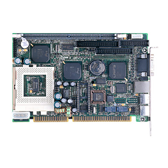
Intelligence • System Health Monitoring: A sensor for the CPU temperature on the NuPRO-595 monitors the CPU temperature, an external sensor for system temperature, case-open indicator, fan speed detection, system voltage monitoring • Windows 98 shut-off: Allows shut-off control from within Windows 98 and through an ATX power supply. - Page 16 Figure 1 Layout of key components: 8 • Introduction...
- Page 17 Figure 2 NuPRO-595 Mechanical Drawing Introduction • 9...
-
Page 18: Chapter 2 Installations
Installations This chapter provides information on how to use the jumpers and connectors on the NuPRO-595 in order to set up a workable system. The topics covered are: ♦ CPU Installation ♦ Memory Installation ♦ Jumpers on the NuPRO-595 ♦ Connectors on the NuPRO-595 ♦... -
Page 19: Cpu Installation
CPU Installation The NuPRO-595 Industrial CPU Board supports a Socket7 processor socket for Intel Pentium MMX, Low power Pentium, AMD K6-2/-3 and Cyrix MII processors. The Socket7 connector comes with a lever to secure the processor. Before inserting the CPU, make sure the lever is raised perpendicular to the socket and the notch on the corner of the CPU corresponds with the notch on the inside of the socket. - Page 20 Figure3 Jumper Locations on the NuPRO-595 12 • Installations...
- Page 21 JP7: CPU Core Multiplier The table below shows the correct setting to match the CPU frequency. CPU Type CPU Frequency 2 x 66MHz 133MHz 2.5x 66MHz 166MHz Intel Pentium CPU 3 x 66MHz 200MHz 3.5x 66MHz 233MHz 2(6) x 66MHz 133(400)MHz AMD K6-2(K6-3) 2.5 x 66MHz 166MHz...
- Page 22 CPU Type CPU Frequency 3.5 x 66MHz 233MHz 4.0 x 66MHz 266MHz 4.5 x 66MHz AMD K6-2(K6-3) 300MHz 5.0 x 66MHz 333MHz 5.5 x 66MHz 366MHz 2.5 x 66MHz 166MHz Low Power Pentium 4.0 x 66MHz 266MHz 14 • Installations...
- Page 23 CPU Type CPU Frequency 2 x 66MHz 133MHz 2.5x 66MHz 166MHz Cyrix MII 3 x 66MHz 200MHz 3.5x 66MHz 233MHz JP1 LCD Power Setting 3.3V Setting 5V Setting JP2: Clear CMOS Content Setting Function Pin 2-3 Normal operation Short/Closed Pin 1-2 Clear CMOS Content Short/Closed Installations •...
- Page 24 JP9 : CPU Core voltage VCORE 1.9V 2.0V 2.1V 2.2V 16 • Installations...
- Page 25 VCORE 2.3V 2.4V 2.8V JP4 , JP5: CPU VI/O Voltage 2.5V 3.3V Installations • 17...
-
Page 26: Connectors On The Nupro-595
JP11 , JP12 , JP13: COM2 OUTPUT MODE SETTING COM2 OUTPUT JP11 JP12 JP13 MODE RS-232 RS-422 RS-485 Connectors on the NuPRO-595 The connectors on the NuPRO-595 allow you to connect external devices such as keyboard, floppy disk drives, hard disk drives, printers, etc. The following tables list the connectors on NuPRO-595 and their respective functions. - Page 27 Figure 4 Connector Locations on the NuPRO-595 Installations • 19...
- Page 28 CN4: Miscellaneous Connector The Miscellaneous connector is a 20-pin header that provides interfaces for the following functions. Power LED PC Speaker Keylock Reset Switch Hard Disk LED ATX Power Input ATX Power On Switch Speaker: Pins 11 - 14 This connector provides an interface to a speaker for audio tone generation. An 8-ohm speaker is recommended.
- Page 29 ATX Power ON Switch: Pins19 and 20 This 2-pin connector is an “ATX Power Supply On/Off Switch” on the system that connects to the power switch on the case. When pressed, the power switch will force the system to power on. When pressed again, it will force the system to power off.
- Page 30 CN1: External Keyboard Connector Pin # Signal Name Keyboard clock Keyboard data IDE1: EIDE Connectors IDE1: Primary IDE Connector Signal Name Pin # Pin # Signal Name Reset IDE Ground Host data 7 Host data 8 Host data 6 Host data 9 Host data 5 Host data 10 Host data 4...
- Page 31 CN3: Floppy Drive Connector CN3 is a 34-pin header and will support up to 2.88MB floppy drives. Signal Name Pin # Pin # Signal Name Drive density Ground selection Ground No connect Drive density Ground selection Ground Index Ground Motor enable 0 Ground Drive select 1 Ground...
- Page 32 CN5: Flat Panel LCD Connector CN5 is a 50-pin (dual in line header) for flat panel LCD displays. The following shows the pin assignments of this connector. Signal Name Pin # Pin # Signal Name VCLK PD10 5V 0R 3.3V 5V 0R 3.3V SHFCLK ENABKL...
- Page 33 Flat Panel Display Interface Pin Descriptions Mono Mono Mono Color Color Color Color Color Color Color Color Color TFT+HRSTN-SSSTN-SSSTN-DDSTN-DD 8-bit 16-bit 8-bit 16-bit Pin Name 8-bit 8-bit 16-bit 9/12/16 bit18/24 bit 36-bit 18/24 bit 24-bit (4bP) (4bP) (4bP) (4bP) Installations • 25...
- Page 34 SHFCLK SHFCLK SHFCLK SHFCLK SHFCLK SHFCLK SHFCLK SHFCLK SHFCLK SHFCLK SHFCLK SHFCLK SHFCLK Pixels/Clk: 2-2/3 5-1/3 2-2/3 5-1/3 CN2: Parallel Port Connector The following table describes the pin out assignments of this connector. Signal Name Pin # Pin # Signal Name Line printer strobe AutoFeed PD0, parallel data 0...
- Page 35 CN10: COM2 Serial Port CN10, a 10-pin header connector, is the onboard COM2 serial port of the NuPRO-595. The following table shows its pin assignments. Pin # Signal Name RS-232 R2-422 RS-485 DATA- DATA+ RTS- RTS+ CTS+ CTS- CN9: PS/2 Keyboard Connector Pin # Signal Name Keyboard data...
- Page 36 CN6: VGA CRT Connector The pin assignments of the CN6 VGA CRT connector are as follows: Signal Name Signal Name Green Blue N.C. N.C. N.C. N.C. HSYNC VSYNC 28 • Installations...
- Page 37 CN7: RJ45 Connector This connector is for the 10/100Mbps Ethernet capability of the CPU board. The figure below shows the pin out assignments of this connector and its corresponding input jack. TD+(pin#1) T D-(pin#2) RD+(pin#3) RD-(pin#6) FN1: CPU Fan Power Connector FN1 is a 3-pin header for the CPU fan.
- Page 38 LED1: LAN Activity Indicators A and B are Green LED indicators located at the bracket side of the CPU board that shows LAN activity and the transfer rate in progress. Refer to the following table for the functions of each LED status. A (up) B (down) A(Speed...
-
Page 39: Watchdog Timer Configuration
Watchdog Timer Configuration The function of the watchdog timer is to reset the system automatically. It contains a one-second/minute resolution down counter, CRF2 of logical device 8, and two Watchdog control registers, WDT_CTRL0 and WDT_CTRL1 of logical device 8. We can uses compatible PNP protocol to access configuration registers for setting up watchdog timer configuration. - Page 40 MOV DX,3F0H MOV AL,0E2H ;device 7, CRE2 OUT DX,AL MOV DX,3F1H MOV AL,0AH ;Watch Dog Timer Output OUT DX,AL MOV DX,3F0H MOV AL,2AH ;CR2A OUT DX,AL MOV DX,3F1H MOV AL,80H ;bit7=0 -> KBRST, bit7=1 -> GP12 OUT DX,AL MOV DX,3F0H MOV AL,07H OUT DX,AL MOV DX,3F1H...
-
Page 41: Disk On Chip Address
MOV DX,3F0H MOV AL,07H OUT DX,AL MOV DX,3F1H MOV AL,08H OUT DX,AL MOV DX,3F0H MOV AL,0F2H ;CRF2 OUT DX,AL MOV DX,3F1H MOV AL,0FH ;Time-out occurs after the value of CRF2 OUT DX,AL ;range 1~255, 00 -> disable Time-out ;--------------------------------------- ;Exit extended function mode ;--------------------------------------- MOV DX,3F0H MOV AL,0AAH... -
Page 42: Chapter 3 Bios Configuration
BIOS Configuration This chapter describes the different settings available in the Award BIOS. The topics covered in this chapter are as follows: BIOS Introduction The Award BIOS (Basic Input/Output Subroutine) installed in your computer system’s ROM supports Intel Pentium & AMD K6-2/3 processors. The BIOS provides critical low-level support for standard devices such as disk drives, serial ports, and parallel ports. -
Page 43: Bios Setup
BIOS Setup The Award BIOS provides a Setup utility program for specifying the system configurations and settings. The BIOS ROM of the system stores the Setup utility. When you turn on the computer, the Award BIOS is immediately activated. Pressing the <Del> key immediately allows you to enter the Setup utility. - Page 44 Note: After making and saving system changes with Setup, you find that your computer cannot boot, the Award BIOS supports an override to the CMOS settings that resets your system to its default. We strongly recommend that you avoid making any changes to the chipset defaults.
- Page 45 Date The date format is: Sun to Sat (read only) Month 1 to 12 Date 1 to 31 Year 1994 to 2079 To set the date, highlight the “Date” field and use the PageUp/ PageDown or +/- keys to set the current time. Time The time format is: Hour...
- Page 46 The SIZE item automatically adjust according to the configuration. MODE (for IDE HDD only) : Auto Auto-detect the HDD mode <Default> Normal HD < 528MB Large For MS-DOS only HD > 528MB and supports Logical Block Addressing Note: The specifications of your drive must match with the drive table. The hard disk will not work properly if you enter incorrect information in these fields.
- Page 47 Halt On This field determines whether the system will halt if an error is detected during power up. The system boot will not be halted for any error that No Errors may be detected. All Errors Whenever the BIOS detects a non-fatal error, <Default>...
-
Page 48: Bios Features Setup
BIOS Features Setup This section allows you to configure and improve your system and allows you to set up some system features according to your preference. ROM / PCI ISA BIOS BIOS FEATURES SETUP AWARD SOFTWARE, INC Virus Warning : Disabled Video BIOS Shadow : Enabled CPU Internal Cache... - Page 49 CPU Internal Cache / External Cache Cache memory is additional memory that is much faster than conventional DRAM (system memory). CPUs from 486-type on contain internal cache memory, and most, but not all, modern PCs have additional (external) cache memory. When the CPU requests data, the system transfers the requested data from the main DRAM into cache memory, for even faster access by the CPU.
- Page 50 Boot Up Floppy Seek The BIOS will seek whether or not the floppy drive Enabled installed has 40 or 80 tracks. 360K type has 40 <Default> tracks while 760K, 1.2M and 1.44M all have 80 tracks BIOS will not search the type of floppy disk drive by Disabled track number Boot Up NumLock Status...
- Page 51 Security Option This field allows you to limit access to the System and Setup. The system always boots up and prompts for the Setup Supervisor Password only when the Setup utility is <Default> called up The system prompts for the User Password every System time you boot up Note: To disable security, select PASSWORD SETTING at Main Menu...
-
Page 52: Chipset Features Setup
Chipset Features Setup This Setup menu controls the configuration of the chipset. ROM PCI/ISA BIOS CHIPSET FEATURES SETUP AWARD SOFTWARE INC. *Auto Configuration : Disabled Power-Supply Type : AT Spread Spectrum : Disabled *DRAM Leadoff Timing : 11/7/3 Case Open_Warning : Enabled *DRAM Read Burst (EDO/FP) : X444/x444... - Page 53 8 Bit I/O Recovery Time The recovery time is the length of time, which the system delays after the completion of an input/output request. The CPU clocks measure it. This delay takes place because the CPU is operating much faster than the input/output bus that the CPU must be delayed to allow for the completion of the I/O.
- Page 54 CPU Warning Temperature This field sets the threshold temperature at which an alert is sounded through the system’s speaker. The CPU temperature is monitored by the onboard thermal sensor to prevent the CPU from overheating. Current System/CPU Temperature These read-only fields reflect the functions of the hardware thermal sensor that monitors the CPU and system temperatures to ensure the system is stable.
-
Page 55: Power Management Setup
Power Management Setup The Power Management Setup allows you to save energy of your system effectively. It will shut down the hard disk and turn off video display after a period of inactivity. ROM PCI/ISA BIOS POWER MANAGEMENT SETUP AWARD SOFTWARE, INC. ACPI Function : Enabled ** Reload Global Timer Events **... - Page 56 PM Control by APM This field allows you to use the Advanced Power Management device to enhance the Max. Power Saving mode and stop the CPU’s internal clock. The default setting of this field is Yes. Video Off Method This field defines the Video Off features. There are three options. This selection will cause the system to turn off the V/HSYNC + Blank Vertical and horizontal synchronization ports and...
- Page 57 Standby Mode After the selected period of system inactivity, the fixed disk drive and the video shut off while all other devices still operate at full speed. Disabled Don’t Enter the Standby mode <Default> 1 Hour After 1 hour of system inactivity, enter Standby mode 40 min After 40 min of system inactivity, enter Standby mode 30 min...
- Page 58 HDD Power Down When enabled, and after the set time of system inactivity, the hard disk drive will be powered down while all other devices remain active. Disabled Don’t Enter the HDD power down mode <Default> 1 min ~ 15 min After the set time of system inactivity, HDD power down Throttle Duty Cycle When the system enters Doze mode, the CPU clock runs only part of the time.
- Page 59 CPUFAN Off In Suspend The fan of CPU is stopped by the BIOS when in Suspend mode. Enabled The fan of CPU stops in suspend mode. <Default> Disabled The fan is always active. PowerOn by Ring/Wake Up On Lan Enabled Wake up the system from modem or lan <Default>...
- Page 60 Panel-9 800x600 TFT Color Panel (Large BIOS only) Panel-10 800x600 Dual Scan STN Color Panel (Large BIOS only) Panel-11 800x600 Dual Scan STN Color Panel (Large BIOS only) Panel-12 1024x768 TFT Color Panel (Large BIOS only) Panel-13 1280x1024 Dual Scan STN Color Panel (Large BIOS only) Panel-14 1024x600 Dual Scan STN Color Panel (Large BIOS only) Panel-15...
-
Page 61: Pnp Os Installed
PNP/PCI Configuration This option configures the PCI bus system. All PCI bus systems on the system use INT#, thus all insta lled PCI boards must be set to this value. ROM PCI/ISA BIOS PNP/PCI CONFIGURATION AWARD SOFTWARE INC. PNP OS Installed : No PCI IDE IRQ Map To : PCI-AUTO... - Page 62 Reset Configuration Data This field allows you to determine whether to reset the configuration data or not. The default value is Disabled. IRQ3/4/5/7/9/10/11/12/14/15, DMA0/1/3/5/6/7 assigned to These fields allow you to determine the IRQ/DMA assigned to the ISA bus and is not available to any PCI slot. PCI IDE IRQ Map To BIOS will scan for PCI IDE devices &...
- Page 63 Load BIOS Defaults This option allows you to load the troubleshooting default values permanently stored in the BIOS ROM. These default settings are non-optimal and disable all high-performance features. ROM PCI/ISA BIOS CMOS SETUP UTILITY AWARD SOFTWARE, INC. STANDARD CMOS SETUP INTEGRATED PERIPHERALS BIOS FEATURES SETUP SUPERVISOR PASSWORD...
- Page 64 Integrated Peripherals This option sets your hard disk configuration, mode and port. ROM PCI/ISA BIOS INTEGRATED PERIPHERALSP AWARD SOFTWARE INC. IDE HDD Block Mode : Enabled Onboard Parallel Port : 378/IRQ7 IDE Primary Master PIO : Auto Parallel Port Mode : SPP IDE Primary Slave PIO : Auto...
- Page 65 IDE Primary Master/Slave UDMA These fields allow your system to improve disk I/O throughput to 33Mb/sec with the Ultra DMA/33 feature. The options are Auto <Default> and Disabled. On-Chip Primary PCI IDE The integrated peripheral controller contains an IDE interface with support for two IDE channels.
- Page 66 Parallel Port Mode This field allows you to determine parallel port mode function. SPP (Standard Parallel Port) normal Printer Port,150KB/sec transfer speed (Enhanced Parallel Port), 2MB/sec transfer speed, the system supports EPP 1.7 and EPP 1.9 ECP (Extended Capabilities Port), 4MB/sec transfer speed 58 •...
- Page 67 Supervisor / User Password These two options set the system password. Supervisor Password sets a password that will be used to protect the system and Setup utility. User Password sets a password that will be used exclusively on the system. To specify a password, highlight the type you want and press <Enter>.
- Page 68 IDE HDD Auto Detection This option detects the parameters of an IDE hard disk drive, and automatically enters them into the Standard CMOS Setup screen. ROM PCI/ISA BIOS STANDARD CMOS SETUP AWARD SOFTWARE, INC. HARD DISKS TYPE SIZE CYLS HEAD PRECOMP LANDZ SECTOR...
- Page 69 Save & Exit Setup This option allows you to determine whether to accept the modifications or not. If you type “Y”, you will quit the setup utility and save all changes into the CMOS memory. If you type “N”, you will return to Setup utility. ROM PCI/ISA BIOS CMOS SETUP UTILITY AWARD SOFTWARE, INC.
-
Page 70: Chapter 4 Intel Piix Bus Master Ide Driver Installation
Intel PIIX Bus Master IDE Driver Installation This chapter describes the installation procedure for Intel PCI ISA IDE Xcelerator(PIIX) Bus Master IDE Drivers for Windows 95. This chapter contains the following sections: System Requirements61 Installing the Software61 62 • Intel PIIX Bus Master IDE Driver Installation... -
Page 71: System Requirements
System Requirements This section describes system requirements for the PIIX Bus Master IDE Device Driver for Windows 95 . This driver has been designed for and tested with Windows 95 only. This driver will only install on systems with Windows The system must contain a supported Intel processor and chipset configuration. -
Page 72: Installing The Software
Installing the Software This subsection describes how to install the software on a system where Windows 95 is installed. Note: Record the location of the Windows 95 directory before installing the driver. Check the System Requirements. Windows 95 must be fully installed and running on the system prior to running this software. - Page 73 If a New Hardware Found dialog box is displayed requesting the location of the drivers, use the mouse to click on the scrollbar and click on the <Windows 95 directory>\System\IOSubSys path: For example: Click on C:\WINDOWS\SYSTEM\IOSUBSYS\ Click OK. Select Yes, when prompted to re-start Windows 95. Note: After installation, the following driver and related files are stored as listed.
-
Page 74: Chapter 5 Vga Driver Installation
VGA Driver Installation This chapter provides information on how to install the C&T 69000 VGA drivers that come in the two floppy diskettes with the package. Please follow the instructions set forth in this chapter carefully. Please note that there must be relevant software installed in your system before you could proceed to install the VGA drivers. -
Page 75: Installing The Drivers For Windows 95
Installing the Drivers for Windows 95 The following section describes the normal display driver installation procedures for Windows 95. Use the following procedures when installing the display drivers for Windows 95. Click Start. Select Settings, then click the Control Panel icon. Double click Display. -
Page 76: Installing The Drivers For Windows 98
Installing the Drivers for Windows 98 The following section describes the normal display driver installation procedures for Windows 98. Use the following procedures when installing the display drivers for Windows 98. Insert the diskette/CD containing the C&T 69000 VGA driver for Windows 98 to the floppy disk drive/CD-ROM drive, then run CTW98600.exe. -
Page 77: Installing The Drivers For Windows Nt 4.0
Installing the Drivers for Windows NT 4.0 IMPORTANT: You should install the Windows NT 4.0 Service Pack 5 first before installing the C&T 69000 VGA drivers. If you don't have the Windows NT 4.0 Service Pack 5, please contact your software vendor or download it from Microsoft's web site. -
Page 78: Chapter 6 Lan Driver Installation Guide
LAN Driver Installation Guide This chapter describes LAN features and driver installation of the onboard Intel 82559 Ethernet controller. Introduction Intel 82559 is a 32-bit 10/100MBps Ethernet controller for PCI local bus -compliant PCs. It supports the bus mastering architecture, and Auto-negotiation feature which make it possible to combine one common type of Ethernet cabling –... -
Page 79: Features
Features • Conforms to the Ethernet IEEE 802.3u standard • Compatible with PCI Local Bus Revision 2.1 specification • IEEE 802.3u Auto-Negotiation for automatic speed selection • Supports Full-Duplex/Half-Duplex Operation • Provides 32-bit bus mastering data transfer • Supports 10Mbps and 100Mbps operation in a single port •... -
Page 80: Running Diagnostics
Running Diagnostics The NuPRO-595 comes with two diskettes containing drivers and diagnostic software supporting the Intel 82559 Ethernet controller. Follow the steps below to use the Setup Utility. file SETUP.EXE typing a:\setup D:\NUPRO\NuPRO595\LAN DRIVER\setup.exe prompt, assuming your floppy disk drive is drive A. Upon doing so, the system starts the Setup Utility and shows the following screen. - Page 81 Selecting View adapter configuration will show the following. 8255x-based PCI EtherExpress™ adapter Setup V4.21 View adapter configuration Adapter type:…………………… Adapter part number:………….. Network address:………………. Interrupt:………………………… Bus:……………………………… Slot:……………………………… Device:………………………….. Network speed:………………… Physical layer device:…………. Duplex:………………………….. Adapter capabilities: 100BaseTX, full or half duplex. 10BaseT, full or half duplex.
- Page 82 Selecting Install network drivers will show the following screen. 8255x-based PCI EtherExpress™ adapter Setup V4.21 Main Menu Install network drivers Novel Microsoft Other Exit Setup Each of the three items will show the operating procedures for you. Choose OTHER if you use a network operating system from a manufacturer not on this list (such as Banyan or UNIX).
- Page 83 Selecting View Help files under the Main menu will show the following screen. 8255x-based PCI EtherExpress™ adapter Setup V4.21 Main Menu Installing Intel® PRO/100+ server and client adapter drivers All users Novell network drivers Unix network drivers Other network drivers Select = ↑↓...
-
Page 84: Chapter 7 Hardware Doctor Utility
Hardware Doctor Utility This chapter introduces Hardware Doctor Utility that comes with the CPU board in conjunction with the onboard hardware monitoring IC. The sections in the following pages describe the functions of the utility. Hardware Doctor is a self-diagnostic system for PC and must be used with Winbond’s W83781D IC series products. - Page 85 The following screen appears upon clicking on the Hardware Doctor icon. Clicking on the upper left corner button would show you the three items as following: Hardware Doctor Utility • 77...
- Page 86 User can set all limits to default value by choosing the “default” item under “file” dialogue window. Set all Limits to Default: If users want to change CPU, please set all limits to default after replacing new CPU and the CPU working voltage Vcore will be load automatically. When Change another CPU, please see Default.
- Page 87 Case Open: If your PC case has a sensor for this functions , after marking this item , once the PC case is opened, the warning message will pop up and never disable unless you key in the correct password. Exit: Choosing the “X”...
- Page 88 Note: Only the fan with three output pins can be monitored! Temperature: All temperature-monitoring items only permit users to change the high limit, and the low limit will be set automatically as the high limit minus 5 degree C. Once the CPU/System temperature over the high limit, the warning message will pop up and status will turn "Red".
-
Page 89: Product Warranty/Service
Product Warranty/Service ADLINK warrants that equipment furnished will be free from defects in material and workmanship for a period of one year from the date of shipment. During the warranty period, we shall, at our option, either repair or replace any product that proves to be defective under normal operation. This warranty shall not apply to equipment that has been previously repaired or altered outside our plant in any way as to, in the judgment of the manufacturer, affect its reliability.
Need help?
Do you have a question about the NuPRO-595 Series and is the answer not in the manual?
Questions and answers