Sign In
Upload
Manuals
Brands
ADLINK Technology Manuals
Motherboard
NuPRO-842 Series
ADLINK Technology NuPRO-842 Series Manuals
Manuals and User Guides for ADLINK Technology NuPRO-842 Series. We have
3
ADLINK Technology NuPRO-842 Series manuals available for free PDF download: User Manual
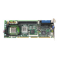
ADLINK Technology NuPRO-842 Series User Manual (62 pages)
Full-Size PICMG 1.0 SBC with Intel Pentium 4
Brand:
ADLINK Technology
| Category:
Motherboard
| Size: 2 MB
Table of Contents
Preface
3
Table of Contents
5
List of Tables
9
List of Figures
11
Introduction
13
Unpacking Checklist
13
Included Items
14
Features
15
Functional Blocks and Main Board
15
Functional Block Diagram
16
Figure 1-1: Functional Block Diagram
16
Main Board Drawing
17
Figure 1-2: Main Board Drawing
17
Intel® Pentium® 4 Processor
18
The Intel® 845GV GMCH
18
The Intel® 82801DB ICH4
18
Watchdog Timer
19
Video
19
Ethernet Interfaces
19
Serial I/O
19
IEEE-1284 Parallel Port/Printer Interface
20
Universal Serial Bus (USB)
20
IDE Controller and Floppy Interface Controller
20
Keyboard/Mouse Controller
20
Software
21
Specifications
21
Compliant Specifications
21
Form Factor
21
Cpu/Cache
21
Chipset
21
Host Memory
22
Bios
22
Gigabit Ethernet
22
Graphic Display
22
USB Interface
22
IDE Ports
22
Super I/O and WDT
23
OS Compatibility
23
Environment
23
Safety Certifications
23
Jumpers and Connectors
25
Nupro-842 Board Outline and Illustration
26
Nupro-842 Top View
26
Figure 2-1: Nupro-842 Top View
27
Table 2-1: Nupro-842 Connectors
28
VGA Connector
29
COM1/COM2 Pin Header
29
Table 2-2: VGA Connector
29
Table 2-3: COM1/COM2 Pin Header
29
LAN RJ-45 Connector
30
Parallel Port Connector
30
Table 2-4: LAN RJ-45 Connector
30
Table 2-5: Parallel Port Connector
30
Case Open Connector
31
CPU Fan1/Fan2 Connector
31
Integrated PS/2 KBD/MS Connector
31
Table 2-6: Case Open Connector Pin Definition
31
Table 2-7: Fan1/Fan2 Connector Pin Definition
31
Table 2-8: PS/2 Keyboard & Mouse Connector Pin Definition
31
Floppy Disk Connector
32
Table 2-9: Floppy Connector Pin Definition
32
Primary/Secondary IDE Connector
33
Table 2-10: IDE Connector Pin Definition
33
Front Panel Pin Header
34
Table 2-11: Front Panel Pin Definition
34
Mini PCI Socket
35
Table 2-12: Mini PCI Socket Pin Definition
35
USB Connector
36
AC'97 Connector
36
Table 2-13: USB Connectors Pin Definition
36
Table 2-14: AC'97 Connector
36
USB Pin Header
37
Thermal Connector
37
External KB/MS Connector
37
Nupro-842 Jumper Setting
37
Table 2-15: USB Pin Header
37
Table 2-16: Thermal Connector
37
Table 2-17: External KB/MS Connector
37
Clear CMOS
38
Table 2-18: Jumpers Definitions
38
Table 2-19: Clear CMOS RTC RAM
38
FSB Frequency
39
Table 2-20: FSB Frequency
39
COM2 Function Selection
40
Table 2-21: COM2 Function Selection
40
COM2 Mode Selection
41
Table 2-22: COM2 Mode Selection
41
Getting Started
43
CPU Installation
43
Memory Installation
43
Memory Configuration Options
44
Installing Memory Modules
44
Figure 3-1: DIMM Sockets
44
Figure 3-2: Inserting DIMM into Socket
44
Connecting IDE Devices to the Nupro-842
45
BIOS Configuration Overview
45
Operating System Installation
46
Device Driver Installation
47
Intel® 845GV Chipset
47
System Requirements
47
Hardware Configuration File Installation
47
Driver Installation
48
VGA Driver Installation
48
LAN Driver Installation
50
Watchdog Timer
53
Watchdog Timer Overview
53
Using the Watchdog in an Application
53
Figure 5-1: Watchdog Timer Architecture
53
DB-842DVI Display Interface
55
Figure 6-1: DB-842DVI Functional Block Diagram
55
DB-842DVI Jumpers and Pinouts
56
Table 6-1: Flat Panel Voltage Selection (JP1)
56
Table 6-2: LVDS Panel Enable (JP2)
56
Table 6-3: DVI Panel Connector (CN1)
57
Table 6-4: LVDS Panel Connector (CN2)
57
Table 6-5: TTL Panel Connector
58
Important Safety Instructions
59
Getting Service
61
Advertisement
ADLINK Technology NuPRO-842 Series User Manual (58 pages)
Full-Size PICMG 1.0 SBC with Intel Pentium 4
Brand:
ADLINK Technology
| Category:
Motherboard
| Size: 0 MB
Table of Contents
Table of Contents
5
List of Tables
9
1 Introduction
11
Unpacking Checklist
11
Included Items
12
Features
13
Functional Blocks and Main Board
13
Functional Block Diagram
14
Figure 1-1: Functional Block Diagram
14
Main Board Drawing
15
Figure 1-2: Main Board Drawing
15
Intel® Pentium® 4 Processor
16
The Intel® 845GV Graphics Chipset Memory Controller Hub (GMCH)
16
The Intel® 82801DB I/O Controller Hub 4 (ICH4)
16
Watchdog Timer
17
Video
17
Ethernet Interfaces
17
Serial I/O
17
IEEE-1284 Parallel Port/Printer Interface
18
Universal Serial Bus (USB)
18
IDE Controller and Floppy Interface Controller
18
Keyboard/Mouse Controller
18
Software
19
Specifications
19
Compliant Specifications
19
Form Factor
19
Cpu/Cache
19
Chipset
19
Host Memory
20
Bios
20
Gigabit Ethernet
20
Graphic Display
20
USB Interface
20
IDE Ports
20
Super I/O and WDT
21
OS Compatibility
21
Environment
21
Safety Certifications
21
2 Jumpers and Connectors
23
Nupro-842 Board Outline and Illustration
24
Nupro-842 Top View
24
Figure 2-1: Nupro-842 Top View
25
Table 2-1: Nupro-842 Connectors
26
VGA Connector
27
COM1/COM2 Pin Header
27
Table 2-2: VGA Connector
27
Table 2-3: COM1/COM2 Pin Header
27
LAN RJ-45 Connector
28
Parallel Port Connector
28
Table 2-4: LAN RJ-45 Connector
28
Table 2-5: Parallel Port Connector
28
Case Open Connector
29
CPU Fan1/Fan2 Connector
29
Integrated PS/2 KBD/MS Connector
29
Table 2-6: Case Open Connector Pin Definition
29
Table 2-7: Fan1/Fan2 Connector Pin Definition
29
Table 2-8: PS/2 Keyboard & Mouse Connector Pin Definition
29
Floppy Disk Connector
30
Table 2-9: Floppy Connector Pin Definition
30
Primary/Secondary IDE Connector
31
Table 2-10: IDE Connector Pin Definition
31
Front Panel Pin Header
32
Table 2-11: Front Panel Pin Definition
32
Mini PCI Socket
33
Table 2-12: Mini PCI Socket Pin Definition
33
USB Connector
34
AC'97 Connector
34
Table 2-13: USB Connectors Pin Definition
34
Table 2-14: AC'97 Connector
34
USB Pin Header
35
Thermal Connector
35
External KB/MS Connector
35
Nupro-842 Jumper Setting
35
Table 2-15: USB Pin Header
35
Table 2-16: Thermal Connector
35
Table 2-17: External KB/MS Connector
35
Clear CMOS
36
Table 2-18: Jumpers Definitions
36
Table 2-19: Clear CMOS RTC RAM
36
FSB Frequency
37
Table 2-20: FSB Frequency
37
COM2 Function Selection
38
Table 2-21: COM2 Function Selection
38
COM2 Mode Selection
39
Table 2-22: COM2 Mode Selection
39
3 Getting Started
41
CPU Installation
41
Memory Installation
41
Memory Configuration Options
42
Installing Memory Modules
42
Figure 3-1: DIMM Sockets
42
Figure 3-2: Inserting DIMM into Socket
42
Connecting IDE Devices to the Nupro-842
43
BIOS Configuration Overview
43
Operating System Installation
44
4 Device Driver Installation
45
Intel® 845GV Chipset
45
System Requirements
45
Hardware Configuration File Installation
45
Driver Installation
46
VGA Driver Installation
46
LAN Driver Installation
48
5 Watchdog Timer
51
Watchdog Timer Overview
51
Using the Watchdog in an Application
51
Figure 5-1: Watchdog Timer Architecture
51
6 DB-842DVI Display Interface
53
Figure 6-1: DB-842DVI Functional Block Diagram
53
DB-842DVI Jumpers and Pinouts
54
Table 6-1: Flat Panel Voltage Selection (JP1)
54
Table 6-2: LVDS Panel Enable (JP2)
54
Table 6-3: DVI Panel Connector (CN1)
55
Table 6-4: LVDS Panel Connector (CN2)
55
Table 6-5: TTL Panel Connector
56
Warranty Policy
57
ADLINK Technology NuPRO-842 Series User Manual (53 pages)
Full-Size PICMG 1.0 Single Board Computer with Pentium 4 CPU
Brand:
ADLINK Technology
| Category:
Motherboard
| Size: 0 MB
Table of Contents
Table of Contents
7
How to Use this Guide
9
Chapter 1 Introduction
11
Unpacking Checklist
12
Features
13
Functional Blocks and Main Board
14
Intel Pentium 4 Processor
16
The Intel® 845GV Graphics Chipset Memory Controller Hub (GMCH)
16
The Intel® 82801DB I/O Controller Hub 4 (ICH4)
16
Watchdog Timer
16
Video
17
Ethernet Interfaces
17
Serial I/O
17
IEEE-1284 Parallel Port/Printer Interface
17
Universal Serial Bus (USB)
17
IDE Controller and Floppy Interface Controller
18
Keyboard/Mouse Controller
18
Software
18
Specifications
19
Chapter 2 Jumpers and Connectors
23
Nupro-842 Board Outline and Illustration
24
Nupro-842 Top View
24
VGA Connector
27
COM1/COM2 Pin Header
28
Gigabit Ethernet (RJ-45) Connector
28
Parallel Port Connector
29
Case Open Connector
29
CPU Fan1/Fan2 Connector
29
Integrated PS/2 KBD/MS Connector
30
Floppy Disk Connector
30
Primary/Secondary IDE Connector
31
Front Panel Pin Header
32
Mini PCI Socket
33
USB Connector
34
AC'97 Connector
34
USB Pin Header
34
Thermal Connector
34
External KB/MS Connector
35
Nupro-842 Jumper Setting
36
Clear CMOS
36
FSB Frequency
37
COM2 Function Selection
37
COM2 Mode Selection
38
Chapter 3 Getting Started
39
CPU Installation
39
Memory Installation
40
Memory Configuration Options
40
Installing Memory Modules
40
Connecting IDE Devices to the Nupro-842
41
BIOS Configuration Overview
42
Operating System Installation
43
Chapter 4 Device Driver Installation
45
Intel® 845GV Chipset
45
System Requirements
45
Hardware Configuration File Installation
46
Driver Installation
46
VGA Driver Installation
46
LAN Driver Installation
48
Chapter 5 Watchdog Timer
51
Watchdog Timer Overview
51
Using the Watchdog in an Application
52
Warranty Policy
53
Advertisement
Advertisement
Related Products
ADLINK Technology NuPRO-850
ADLINK Technology NuPRO-861
ADLINK Technology NuPRO-865
ADLINK Technology NuPRO-850GV8X
ADLINK Technology NuPRO-850GV
ADLINK Technology NuPRO-842DV/P
ADLINK Technology NuPRO-935A
ADLINK Technology NuPRO-760
ADLINK Technology NuPRO-761
ADLINK Technology NuPRO-591
ADLINK Technology Categories
Computer Hardware
Motherboard
PCI Card
Control Unit
Desktop
More ADLINK Technology Manuals
Login
Sign In
OR
Sign in with Facebook
Sign in with Google
Upload manual
Upload from disk
Upload from URL