
Related Manuals for ADLINK Technology NuPRO-775 Series


Summary of Contents for ADLINK Technology NuPRO-775 Series
- Page 1 NuPRO-775 Series Half Size Socket-370 Pure PCI Industrial SBC User’s Guide Recycled Paper...
- Page 3 Copyright Notice Manual Rev 2.10: August 8, 2001 Part NO: 50-13017-202 This publication is protected by copyright and all rights are reserved. No part of it may be reproduced or transmitted by any means or in any form, without prior consent of the original manufacturer. The information in this document has been carefully checked and is believed to be accurate.
- Page 4 Getting service from ADLINK ♦ Customer Satisfaction is always the most important thing for ADLINK Tech Inc. If you need any help or service, please contact us and get it. ADLINK Technology Inc. Web Site http://www.adlink.com.tw Sales & Service service@adlink.com.tw NuDAQ + USBDAQ nudaq@adlink.com.tw...
-
Page 5: Table Of Contents
Table of Contents Chapter 1 Introduction ..........1 Checklist................1 Description .................2 Features ................3 Specifications..............4 Intelligence .................7 Chapter 2 Installations ..........10 CPU Installation ...............10 Memory Installation............11 Jumpers on the NuPRO-775..........11 Connectors on the NuPRO-775 ........12 Watchdog Timer Configuration ........21 Chapter 3 BIOS Configuration ........24 BIOS Introduction.............25 BIOS Setup ..............25 Chapter 4 Intel 810 Chipset Hardware... -
Page 7: Chapter 1 Introduction
Introduction This manual is designed to give you information on the NuPRO-775 CPU board. The topics covered in this chapter are as follows: • Checklist • Description • Features • Specifications • Intelligence • Layout of Key Components and Dimensions Checklist Please check that your package is complete and contains the items below. -
Page 8: Description
• 1 CD Containing hardware configuration file, VGA Driver, Intel 82559 LAN Driver and Hardware Monitor utility Description The NuPRO-775 is a Celeron/Pentium III Industrial Computer Main board based on the Intel i82810 chipset and is fully designed for harsh industrial environment. -
Page 9: Features
Features • Intel Celeron 300~533MHz, Pentium III 500E/550E, or later version processors • Bus Speed 66/100MHz • Intel i82810 chipset(built-in VGA controller) • Up to 256MB SDRAM system memory • Two 16550 UART compatible ports with RS-232 interface • High speed bi-directional SPP/ECP/EPP parallel port •... -
Page 10: Specifications
Specifications • Processor Socket: Socket-370 connector • Processor: Intel Celeron 300~533MHz, Pentium III 500E/550E, or later version • Bus Speed: 66/100MHz • Chipset: Intel i82810 • Secondary Cache: built in CPU • Memory Sockets: One 168-pin DIMM socket Max. 256MB SDRAM Memory type: PC-100 unbuffered DIMM •... - Page 11 ESD protection to 2KV • Enhanced IDE: Bus Master IDE controller, two EIDE interfaces for up to four devices, support PIO Mode 3/4 or Ultra DMA/66 IDE Hard Disk and ATAPI CD-ROM.,LS120,ZIP • FDD Interface: Two floppy drives (360KB, 720KB, 1.2MB, 1.44MB, 2.88MB) •...
- Page 12 • PCI Compliance: Fully compliant to PCI rev. 2.1 standards • Power supply: ATX • Environmental and Mechanical: Power Consumption: +5V@10A(max), +3.3V@10A(max), +12V@0.6A, -12V@130mA, +5VSB@0.6A Temperature: 0°C to 70°C Humidity: 5% to 95% Dimensions: 185mm x 122mm 6 • Introduction...
-
Page 13: Intelligence
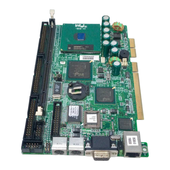
Intelligence • System Health Monitoring: A sensor for the CPU temperature on the NuPRO-775 monitors the CPU temperature, an external sensor system temperature, case-opened indicator, fan-speed detection, system voltages monitoring • Windows 98 shut-off: Allows shut-off control from within Windows 98 and through an ATX power supply. - Page 14 Figure 1 Layout of key components: 8 • Introduction...
- Page 15 Figure 2 NuPRO-775 Mechanical Drawing Introduction • 9...
-
Page 16: Chapter 2 Installations
Installations This chapter provides information on how to use the jumpers and connectors on the NuPRO-775 in order to set up a workable system. The topics covered are: • CPU Installation • Memory Installation • Jumpers on the NuPRO-775 • Connectors on the NuPRO-775 •... -
Page 17: Memory Installation
Memory Installation The NuPRO-775 industrial computer main board supports one 168-pin DIMM socket for a maximum total memory of 256 MB. The memory modules can come in sizes of 16MB, 32MB, 64MB, 128MB, and 256MB SDRAM. Jumpers on the NuPRO-775 The jumpers on the NuPRO-775 allow you to configure your main board according to the needs of your applications. -
Page 18: Connectors On The Nupro-775
Connectors on the NuPRO-775 The connectors on the NuPRO-775 allow you to connect external devices such as keyboard, floppy disk drives, hard disk drives, printers, etc. The following tables list the connectors on NuPRO-775 and their respective functions. CN1: Floppy Drive Connector.............. 14 CN2, CN3: EIDE Connectors............... - Page 19 Figure 3 Connector location on the NuPRO-775 Installations • 13...
-
Page 20: Cn1: Floppy Drive Connector
CN1: Floppy Drive Connector CN1 is a 34-pin header and will support up to 2.88MB floppy drives. Signal Name Pin# Pin# Signal Name Drive density Ground selection Ground No connect Drive density Ground selection Ground Index Ground Motor enable 0 Ground Drive select 1 Ground... -
Page 21: Cn2, Cn3: Eide Connectors
CN2, CN3: EIDE Connectors CN3: Primary IDE Connector Signal Name Pin # Pin # Signal Name Reset IDE Ground Host data 7 Host data 8 Host data 6 Host data 9 Host data 5 Host data 10 Host data 4 Host data 11 Host data 3 Host data 12... -
Page 22: Cn2: Secondary Ide Connecto
CN2: Secondary IDE Connecto: Signal Name Pin # Pin # Signal Name Reset IDE Ground Host data 7 Host data 8 Host data 6 Host data 9 Host data 5 Host data 10 Host data 4 Host data 11 Host data 3 Host data 12 Host data 2 Host data 13... -
Page 23: Cn4, Cn5: Serial Port (Cn5 : Com1, Cn4 : Com2)
CN4, CN5: Serial Port (CN5 : COM1, CN4 : COM2) A 10-pin header connector, is an onboard serial port of the NuPRO-775. The following table shows the pin assignments of this connector. Pin # Signal Name DCD, Data carrier detect RXD, Receive data TXD, Transmit data DTR, Data terminal ready... -
Page 24: Cn9: Parallel Port Connector
CN9: Parallel Port Connector The following table describes the pin out assignments of this connector. Signal Name Pin # Pin # Signal Name Line printer strobe AutoFeed PD0, parallel data 0 Error PD1, parallel data 1 Initialize PD2, parallel data 2 Select PD3, parallel data 3 Ground... -
Page 25: Cn13: Ps/2 Mouse Connector
CN13: PS/2 Mouse Connector Pin # Signal Name Mouse data N.C. N.C. Mouse Clock N.C. CN14: VGA CRT Connector The pin assignments of the CN14 VGA CRT connector are as follows: Signal Name Signal Name Green Blue N.C. N.C. N.C. N.C. -
Page 26: Fn1: Cpu Fan Power Connector
FN1: CPU Fan Power Connector FN1 is a 3-pin header for the CPU fan. The fan must be a 12V fan. Pin # Signal Name Ground +12V Rotation LED1: LAN Activity Indicators A and B are Green LED indicators located at the bracket side of the CPU board that shows LAN activity and the transfer rate in progress. -
Page 27: Watchdog Timer Configuration
Watchdog Timer Configuration The function of the watchdog timer is to reset the system automatically. It contains a one-second/minute resolution down counter, CRF6 of logical device 8, and two Watchdog control registers, CRF5 and CRF7 of logical device 8. We can uses compatible PNP protocol to access configuration registers for setting up watchdog timer configuration. - Page 28 dx,2eh al,30h dx,al dx,2fh al,01h ;enable device 8 dx,al dx,2eh al,07h dx,al dx,2fh al,08h ;device 8 dx,al dx,2eh al,0f7h dx,al ;device 8,CRF7 dx,2fh al,0c0h dx,al dx,2eh al,07h dx,al dx,2fh al,08h dx,al ;device 8 dx,2eh al,0f5h ;device 8, CRF5 dx,al dx,2fh al,00h ;bit3 ->...
- Page 29 dx,2eh al,0aah dx,al .exit ADLINK provides the watchdog programs and subroutines for easy use under DOS, Windows 95/98/2000, and Windows NT, please browse ADLINK CD for detailed information. Installations • 23...
-
Page 30: Chapter 3 Bios Configuration
BIOS Configuration This chapter describes the different settings available in the Award BIOS. The topics covered in this chapter are as follows: Standard CMOS Features ..............26 Advanced BIOS Features..............31 Advanced Chipset Features ..............35 Integrated Peripherals ................. 37 Power Management Setup ..............40 PNP/PCI Configurations ..............45 PC Health Status ................. -
Page 31: Bios Introduction
BIOS Introduction The Award BIOS (Basic Input/Output System) installed in your computer system’s ROM supports Intel Celeron and Pentium III processors. The BIOS provides critical low-level support for standard devices such as disk drives, serial ports, and parallel ports. It also adds virus and password protection as well as special support for detailed fine-tuning of the chipset controlling the entire system. -
Page 32: Standard Cmos Features
The section below the setup items of the Main Menu displays the control keys for this menu. Another section at the bottom of the Main Menu just below the control keys section displays information on the currently highlighted item in the list. Note: After making and saving system changes with Setup, you find that your computer cannot boot, the Award BIOS supports an override to the CMOS settings that resets your system to its... - Page 33 At the bottom of the menu are the control keys for use on this menu. If you need any help in each item field, you can press the <F1> key. It will display the relevant information to help you. The item help at the right-hand side of the menu can give the description about the item.
- Page 34 CMOS Setup Utility – Copyright (C) 1984-2000 Award Software IDE Primary Master IDE HDD Auto-Detection Press Enter Item Help IDE Primary Master Auto Menu Level ►► Access Mode Auto Selects the type of fixed disk. Capacity 6480 MB ‘User type’ will let you select the number of cylinders, heads, Cylinder 12556...
- Page 35 IDE Primary/Secondary Master/Slave Auto <Default> Bios will auto detect the hard disk type. User can assigns the type of hard disk when the Manual access mode is normal. Selects this selection when there is no hard disk in None the system. Access Mode Auto <Default>...
- Page 36 Video This field selects the type of video display card installed in your system. You can choose the following video display cards. For EGA, VGA, SEGA, SVGA or PGA monitor EGA/VGA <Default> adapters. CGA 40 Power up in 40-column mode. CGA 80 Power up in 80-column mode.
-
Page 37: Advanced Bios Features
Advanced BIOS Features This section allows you to configure and improve your system and allows you to set up some system features according to your preference. CMOS Setup Utility – Copyright (C) 1984-2000 Award Software Advanced BIOS Features Virus Warning Disabled Item Help CPU Internal Cache... - Page 38 CPU Internal Cache / External Cache Cache memory is additional memory that is much faster than conventional DRAM (system memory). CPUs from 486-type on up contain internal cache memory, and most, but not all, modern PCs have additional (external) cache memory. When the CPU requests data, the system transfers the requested data from the main DRAM into cache memory, for even faster access by the CPU.
- Page 39 Boot Up Floppy Seek The BIOS will seek whether or not the floppy drive installed has 40 or 80 tracks. 360K type has 40 Enabled <Default> tracks while 760K, 1.2M and 1.44M all have 80 tracks BIOS will not search the type of floppy disk drive Disabled by track number Boot Up NumLock Status...
- Page 40 the system always boots up and prompts for the Setup <Default> Supervisor Password only when the Setup utility is called up the system prompts for the User Password every System time you boot up Note: To disable security, select PASSWORD SETTING at Main Menu and then you will be asked to enter the password.
-
Page 41: Advanced Chipset Features
Advanced Chipset Features This Setup menu controls the configuration of the chipset. CMOS Setup Utility – Copyright (C) 1984-2000 Award Software Advanced Chipset Features SDRAM CAS Latency Time Item Help SDRAM Cycle Time Tras/Trc SDRAM RAS-to-CAS Delay Menu Level ► SDRAM RAS Precharge Time System BIOS Cacheable Disabled... - Page 42 System BIOS Cacheable When this function is enabled, the BIOS ROM’s addresses at F0000H-FFFFFH will be duplicated into the SRAM. It will work with the cache controller that is enabled. Enabled BIOS access cached Disabled <Default> BIOS access not cached Video BIOS Cacheable As with caching the system BIOS above, enabling the Video BIOS cache will cause access to Video BIOS addressed at C0000H to C7FFFH to be...
-
Page 43: Integrated Peripherals
Integrated Peripherals This option sets your hard disk configuration, mode and port. CMOS Setup Utility – Copyright (C) 1984-2000 Award Software Integrated Peripherals On-Chip Primary PCI IDE Enabled Item Help On-Chip Secondary PCI IDE Enabled IDE Primary Master PIO Auto Menu Level ►... - Page 44 The system supports five modes, numbered from 0 (default) to 4, which primarily differ in timing. When Auto is selected, the BIOS will select the best available mode. Auto select which mode that BIOS Auto<Default> communicates with the controller and CPU Mode0~Mode4 User define the PIO mode IDE Primary/Secondary Master/Slave UDMA...
- Page 45 UART Mode Select This field determines the UART mode in your computer. The settings are Normal, IrDA and ASKIR. The default value is Normal. Onboard Parallel Port These fields allow you to select the onboard parallel ports and their addresses. The default value for this port is 378H/IRQ7. Parallel Port Mode To operate the onboard parallel port as Standard Parallel Port only, choose “SPP”.
-
Page 46: Power Management Setup
Power Management Setup The Power Management Setup allows you to save energy of your system effectively. It will shut down the hard disk and turn off video display after a period of inactivity. CMOS Setup Utility – Copyright (C) 1984-2000 Award Software Power Management Setup ACPI Function Enabled... - Page 47 Disabled No power management. Each of the ranges is from 1 min. to 1hr. Except for User Define HDD Power Down which ranges from 1 min. to 15 <Default> min. Min Saving Minimum power management Max Saving Maximum power management. Note: In order to enable the CPU overheat protection feature, the Power Management field should not be set to disabled.
- Page 48 Disabled Don’t Enter the Suspend mode <Default> After 1 hour of system inactivity, enter Suspend 1 Hour mode After 40 min of system inactivity, enter Suspend 40 min mode After 30 min of system inactivity, enter Suspend 30 min mode After 20 min of system inactivity, enter Suspend 20 min mode...
- Page 49 Wake-Up by PCI card/Power On by Ring Enabled Wake up the system from modem or lan <Default> Disabled Disable the modem or lan to wake up the system Intruder# Detection This item is used to detect the system’s case is opened or not. If the case is opened, the system will be shutdown.
- Page 50 interrupts itself and performs the service. If activity is detected from any enabled IRQ channels, the system wakes up from suspended mode. 44 • BIOS Configuration...
-
Page 51: Pnp/Pci Configurations
PNP/PCI Configurations This option configures the PCI bus system. All PCI bus systems on the system use INT#, thus all installed PCI cards must be set to this value. CMOS Setup Utility – Copyright (C) 1984-2000 Award Software PnP/PCI Configurations Reset Configuration Data Enabled Item Help... - Page 52 Memory Resources This sub menu can let you control the memory resource. PCI/VGA Palette Snoop Some non-standard VGA display cards may not show colors properly. This field allows you to set whether MPEG ISA/VESA VGA Cards can work with PCI/VGA or not. PCI/VGA can work with MPEG ISA/VESA VGA Enabled card...
-
Page 53: Pc Health Status
PC Health Status CMOS Setup Utility – Copyright (C) 1984-2000 Award Software PC Health Status CPU Warning Temperature Disabled Item Help Current System Temp. Current CPU1 Temperature Menu Level ► Current CPUFAN1 Speed Current CPUFAN2 Speed VCORE + 2.5V + 3.3V + 5 V +12 V -12 V... -
Page 54: Frequency/Voltage Control
Frequency/Voltage Control CMOS Setup Utility – Copyright (C) 1984-2000 Award Software Frequency/Voltage Control Auto Detect DIMM/PCI Clk Enabled Item Help CPU Clock/Spread Spectrum Default CPU Clock Ratio Menu Level ► : Move Enter : Select +/-/PU/PD : Value F10 : Save ESC : Exit F1 : General Help F5 : Previous Values... -
Page 55: Load Fail-Safe Defaults
Load Fail-Safe Defaults This option allows you to load the troubleshooting default values permanently stored in the BIOS ROM. These default settings are non-optimal and disable all high-performance features. CMOS Setup Utility – Copyright (C) 1984-2000 Award Software ► Standard CMOS Features ►... -
Page 56: Set Supervisor / User Password
Set Supervisor / User Password These two options set the system password. Supervisor Password sets a password that will be used to protect the system and Setup utility. User Password sets a password that will be used exclusively on the system. To specify a password, highlight the type you want and press <Enter>. -
Page 57: Save & Exit Setup
Save & Exit Setup This option allows you to determine whether to accept the modifications or not. If you type “Y”, you will quit the setup utility and save all changes into the CMOS memory. If you type “N”, you will return to Setup utility. CMOS Setup Utility –... -
Page 58: Chapter 4 Intel 810 Chipset Hardware Configuration & Driver Installation
Intel 810 Chipset Hardware Configuration & Driver Installation This chapter describes the installation procedure of Intel 810 chipset Device Driver for Windows 98/95. It contains the following sections: Hardware Configuration File Installation This section describes system requirements of Intel 810 chipset Device Driver. - Page 59 Windows 95 4.00.950a (OSR1) Windows 95 4.00.950 (Original Release) This utility should only be used on desktop systems. The utility must not be executed on notebook or portable systems with or without dock. Installing Hardware Configuration File This subsection describes how to install the hardware configuration file on a system where Windows 98/95 is installed.
-
Page 60: Vga Driver Installation
VGA Driver Installation This section provides information on how to install the VGA driver that come in the Compact Disk with the package. Please follow the instructions set forth in this section carefully. Please note that there must be relevant software installed in your system before you could proceed to install the VGA driver. - Page 61 Follow the screen instructions and use default settings to complete the setup when Windows NT 4.0 is re-started. Intel 810 Chipest Hardware Configuration & Driver Installation • 55...
-
Page 62: Chapter 5 Lan Driver Installation Guide
LAN Driver Installation Guide This chapter describes LAN features and driver installation of the onboard Intel 82559 Ethernet controller. The following items are covered in this chapter: Introduction Intel 82559 is a 32-bit 10/100MBps Ethernet controller for PCI local bus-compliant PCs. It supports the bus mastering architecture, and Auto-negotiation feature which make it possible to combine one common type of Ethernet cabling –... -
Page 63: Software Drivers Support
Software Drivers Support NetWare ODI Drivers Novell NetWare 3.x, 4.x, NetWare LAN WorkPlace TCP/IP, Novell LAN Analyzer for NetWare Packet Drivers FTP PC/TCP, NCSA TCP/IP NDIS Drivers Microsoft LAN Manager V2.x, Windows 3.x, Windows NT 4.0, Windows NT 3.51, Windows 98, Windows 95, SCO3, SCO5; IBM LAN Server 4.0 for DOS and OS/2, and Linux. - Page 64 Selecting View adapter configuration will show the following. 8255x-based PCI EtherExpress™ adapter Setup V4.21 View adapter configuration Adapter type:…………………… Adapter part number:………….. Network address:………………. Interrupt:………………………… Bus:……………………………… Slot:……………………………… Device:………………………….. Network speed:………………… Physical layer device:…………. Duplex:………………………….. Adapter capabilities: 100BaseTX, full or half duplex. 10BaseT, full or half duplex.
- Page 65 Selecting Install network drivers will show the following screen. 8255x-based PCI EtherExpress™ adapter Setup V4.21 Install network drivers Novel Microsoft Other Exit Setup Each of the three items will show the operating procedures for you. Choose OTHER if you use a network operating system from a manufacturer not on this list (such as Banyan or UNIX).
- Page 66 Selecting View Help files under the Main menu will show the following screen. 8255x-based PCI EtherExpress™ adapter Setup V4.21 Installing Intel® PRO/100+ server and client adapter drivers All users Novell network drivers Unix network drivers Other network drivers Select = ↑↓ Display Choices = ↵...
-
Page 67: Hardware Doctor Utility
Hardware Doctor Utility This chapter introduces Hardware Doctor Utility that comes with the CPU board conjunction with onboard hardware monitoring function(embedded in Winbond’s Super I/O chip W83627HF). The sections in the following pages describe the functions of the utility. Hardware Doctor is a self-diagnostic system for PC and must be used with Winbond’s W83781D/W83782D IC series products. - Page 68 The following screen appears upon clicking on the Hardware Doctor icon. Clicking on the upper left corner button would show you the three items as following: User can set all limits to default value by choosing the “default” item under “file” dialogue window.
- Page 69 Set all Limits to Default If users want to change CPU, please set all limits to default after replacing new CPU and the CPU working voltage Vcore will be load automatically. When Change another CPU, please see Default. Save the Setting Limits Limit Adjustment All limits by users can be modified and saved.
- Page 70 Exit Choosing the “X” button on the right corner of the tool bar in Hardware Doctor main menu, the menu will be minimized on the working bar of Windows 98 and serves as a TSR program. Only choosing the "exit" item under the "...
- Page 71 Fan Speed The most popular PC system may only have one fan on the motherboard. When the fan is not connected or doesn't exist, the fan speed column will be indicated "Low speed". At this time, please disable the fan in the "configuration"...
-
Page 72: Product Warranty/Service
Warranty Policy Thank you for choosing ADLINK. To understand your rights and enjoy all the after-sales services we offer, please read the following carefully. Before using ADLINK’s products please read the user manual and follow the instructions exactly. When sending in damaged products for repair, please attach an RMA application form which can be downloaded from: http://rma.adlinktech.com/policy/. - Page 73 • Damage caused by leakage of battery fluid during or after change of batteries by customer/user. • Damage from improper repair by unauthorized ADLINK technicians. • Products with altered and/or damaged serial numbers are not entitled to our service. • This warranty is not transferable or extendible.
Need help?
Do you have a question about the NuPRO-775 Series and is the answer not in the manual?
Questions and answers