Table of Contents
Advertisement
Advertisement
Table of Contents

Related Manuals for True TC400


Summary of Contents for True TC400
- Page 1 TC400 TREADMILL OWNER’S MANUAL MODEL TC400-22 MAN-TC400-22 REV00...
- Page 3 Alle hier gezeigten Produkte sind Prototypen. Das tatsächliche Produkt ausgeliefert wird, kann variieren. Produkt- Spezifi kationen, Funktionen und Software können sich ohne vorherige Ankündigung ändern. In den meisten Fällen bis zu Bedienungsanleitung Bisher besuchen und für Dokumente in weiteren Sprachen fi nden Sie unter https://truefi tness.com/ support/user-manuals/ BELANGRIJK! Alle getoonde producten zijn prototype.
- Page 4 You can count on TRUE Fitness for the best service in the industry, provided by a team focused on optimizing the life of your equipment.
- Page 5 You may receive a shipment that looks intact and discover once the box has been opened that there are hidden damages. Please notify the carrier immediately. TRUE will not be able to fi le a claim if the carrier is not notifi ed in a timely manner.
-
Page 6: Table Of Contents
TENSIONING THE RUNNING BELT..........................33 PREVENTATIVE MAINTENANCE............................34 LONG TERM STORAGE..............................34 STORING THE CHEST STRAP............................34 ADDITIONAL INFORMATION TROUBLESHOOTING................................35 TC400 110V WIRING DIAGRAM............................42 TC400 220V WIRING DIAGRAM............................43 WARRANTY INFORMATION TC400 TREADMILL LIGHT COMMERCIAL LIMITED WARRANTY..................44 TC400 TREADMILL RESIDENTIAL COMMERCIAL LIMITED WARRANTY.................45 TC400 TREADMILL LIMITED WARRANTY...........................46... -
Page 7: Safety Instructions
When using this exercise machine, basic product. precautions should always be followed. • Never operate a TRUE product if it has a damaged • Use this equipment only for its intended use as power cord or electrical plug, or if it has been described in this manual. - Page 8 • Do not remove the motor cover or you may risk injury due to electric shock. Please contact TRUE • While the treadmill is in use, proceed at a speed product support if the motor area needs servicing.
-
Page 9: Power Requirements
POWER REQUIREMENTS Read and understand all instructions before plugging any TRUE power cord into an electrical outlet. DEDICATED LINE This product requires a dedicated line. A dedicated line assures that adequate power is available for safe operation over the life of your TRUE product. -
Page 10: Space Requirements
SPACE REQUIREMENTS TRUE recommends leaving a minimum of 24” (61cm) on each side of the equipment and a 79” (200.7cm) safety zone at the rear of the equipment. 24” (61cm) 24” 79” (61cm) (200.7cm) 24” (61cm) SPECIFICATIONS • DIMENSIONS (L X W X H) 79”... -
Page 11: Warning Decals
WARNING DECALS WARNING: Replace warning labels that may be worn, damaged, or missing. To replace any worn or missing decals contact TRUE product support (service@truefi tness.com // 800.883.8783). console serial number location base serial number location 22-TC4000001A COMPLIANCES This equipment complies with all applicable codes and regulations. For a complete list of compliances, please visit... -
Page 12: Assembly Instructions
Unpacking and assembling of this treadmill is a two person task. VERIFY BOX CONTENTS IMPORTANT! Please verify box contents. If you have questions, or if there are any missing parts, contact product support (service@truefi tness.com // 800.883.8783). TOOLS NEEDED FOR INCLUDED... - Page 13 BOX CONTENTS ITEM DESCRIPTION Base Left Pedestal Right Pedestal Left Handrail Right Handrail Console Rack Console Rear Cover Left Shoulder Cover Top Right Shoulder Cover Top Left Shoulder Cover Bottom Right Shoulder Cover Bottom Safety Key 110V Power Cord 220V Power Cord* 220V Power Inlet Assembly* Hardware Pack Manual...
- Page 14 HARDWARE PACK CONTENTS TC6085 Hardware Pack ITEM DESCRIPTION BRACKET, CENTER POD, CURVED, BLACK TC6061 WASHER, STAR, INTERNAL TOOTH, M8 RT0011 BHCS, M8X75MM PS0103 BHCS, M8X1.25X40MM PS0034 BHCS, M8X1.25X80MM TCS4028 PHMS, M4X0.7X10MM, PHILLIPS TCS4029 ZIP TIE TC6085_005 8MM T-HANDLE ALLEN WRENCH TC6085_003 5MM ALLEN WRENCH TC6085_004...
-
Page 15: Assembly Steps
ASSEMBLY STEPS STEP 1—REMOVE MOTOR COVER AND MOTOR CAP COVERS Tools Used in this Step Parts Used in this Step #2 Phillips Screwdriver PART DESCRIPTION PS0035 SCREW, M5XP0.8X15MM SCA5-15 TC4036LBK SUBASSEMBLY, CAP, MOTOR COVER-LH TC4036RBK SUBASSEMBLY, CAP, MOTOR COVER-RH TC4035BK SUBASSEMBLY, MOTOR COVER 1. - Page 16 OPTIONAL STEP 2—INSTALL 220V POWER INLET ASSEMBLY NOTE: This step is only for units that will be used on a circuit having a nominal rating of more than 110-V. Tools Used in this Step Parts Used in this Step #2 Phillips Screwdriver PART DESCRIPTION TC0033...
- Page 17 STEP 3—ATTACH LEFT AND RIGHT PEDESTALS Tools Used in this Step Parts Used in this Step 5mm Allen Wrench PART DESCRIPTION PS0103 BHCS, M8X75MM RT0011 WASHER, STAR, INTERNAL TOOTH, M8 TC4016LBK SUBASSEMBLY, PEDESTAL UPRIGHT-LH 17mm Wrench TC4016RBK SUBASSEMBLY, PEDESTAL UPRIGHT-RH 1.
- Page 18 STEP 4—ROUTE AND CONNECT LOWER CABLES Tools Used in this Step 7/16” Wrench Carefully make the following cable connections between the right pedestal and the base: • I/O Communication Cable • Power AUXPS Cable • Network Cable • Coaxial Cable NOTE: To fully tighten the coaxial cable nut, use a 7/16”...
- Page 19 STEP 5—ATTACH CONSOLE RACK Tools Used in this Step Parts Used in this Step 5mm Allen Wrench PART DESCRIPTION PS0034 BHCS, M8X1.25X40MM RT0011 WASHER, STAR, INTERNAL TOOTH, M8 TC6061 SUBASSEMBLY, PEDESTAL UPRIGHT-LH CONSOLE RACK 1. Place the console rack on left and right pedestals. 2.
- Page 20 STEP 6—TIGHTEN PEDESTALS AND REATTACH MOTOR AND CAP COVERS Tools Used in this Step Parts Used in this Step #2 Phillips Screwdriver PART DESCRIPTION PS0035 SCREW, M5XP0.8X15MM SCA5-15 TC4036LBK SUBASSEMBLY, CAP, MOTOR COVER-LH TC4036RBK SUBASSEMBLY, CAP, MOTOR COVER-RH 17mm Wrench TC4035BK SUBASSEMBLY, MOTOR COVER 5mm Allen Wrench...
- Page 21 STEP 7—CONNECT PEDESTAL AND CONSOLE RACK CABLES Carefully make the following cable connections between the console rack and the right pedestal: • I/O Communication Cable • Power AUXPS Cable • Network Cable • Coaxial Cable Console Rack Power AUXPS Cable Communication Cable Network...
- Page 22 STEP 8—ATTACH LEFT AND RIGHT HANDRAILS Tools Used in this Step Parts Used in this Step 5mm Allen Wrench PART DESCRIPTION TCS4028 BHCS, M8X1.25X80MM RT0011 WASHER, STAR, INTERNAL TOOTH, M8 TC4018L KIT, HANDRAIL SUBASSEMBLY-LH TC4018R KIT, HANDRAIL SUBASSEMBLY-RH 1. Finger tighten the left and right handrails to the left and right pedestals. 2.
- Page 23 STEP 9—ATTACH SHOULDER COVERS Tools Used in this Step Parts Used in this Step #2 Phillips Screwdriver PART DESCRIPTION TCS4029 PHMS, M4X0.7X10MM, PHILLIPS TC4022LBK SUBASSEMBLY, SHOULDER BOTTOM-LH BLACK TC4022RBK SUBASSEMBLY, SHOULDER BOTTOM-RH BLACK TC4023LBK SUBASSEMBLY, SHOULDER TOP-LH BLACK TC4023RBK SUBASSEMBLY, SHOULDER TOP-RH BLACK 1.
- Page 24 STEP 10—ATTACH CONSOLE AND CONSOLE REAR COVER Tools Used in this Step Parts Used in this Step #2 Phillips Screwdriver PART DESCRIPTION TCS4029 PHMS, M4X0.7X10MM, PHILLIPS TC4033BK SUBASSEMBLY, REAR CONSOLE COVER, BLACK 1. Using a #2 Phillips screwdriver, secure the console to the console mast using the hardware pre-assembled to the console (00567800 // SCREW, M5-.8X12 COMBO PHILLIPS/COMMON TRUSS HEAD - ACG BLACK // QTY 4).
- Page 25 OFF position ( ), and then rocking the power switch back to the ON position ). If it does not reset, or the circuit breaker operates again under normal use, contact TRUE Product Support at 800.883.8783 or service@truefi tness.com.
- Page 26 STEP 12—ATTACH SAFETY KEY 1. Attach the safety key magnet to the front of the center pod. 2. Tie the shorter section of the safety key string to the plate on the console rack. This prevents the safety key from getting lost.
- Page 27 STEP 13—LEVEL THE TREADMILL Once the machine has been moved to it’s designated location: 1. Verify the treadmill is resting on the fl oor and not on any packaging materials. 2. Using a level or estimating by sight, adjust both leveling feet until they contact the fl oor. IMPORTANT! Do not adjust the leveling feet to such a height that they detach or unscrew from the machine.
- Page 28 Your treadmill uses a high-effi cient, low-friction, hard waxed deck and maintenance free belt. For optimal performance, TRUE recommends a 15 minute break in period to help transfer the wax from the deck to the belt. On a brand new unit, ensuring the wax has been adequately worked into the belt helps alleviate alignment and tension issues.
-
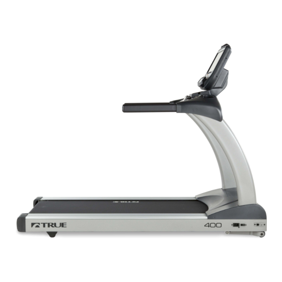
Page 29: Product Features Treadmill Overview
PRODUCT FEATURES TREADMILL OVERVIEW Console Assembly Safety (E-Stop) Quick Access Keys Contact Heart Rate Pads Straddle Covers R REFERENCE: Belt Belt Adjustment Bolts On/Off Switch, Circuit Breaker, and Power Cord Leveling Feet Console Assembly Straddle Covers The console allows the user to set up a workout program Stationary covers on either side of the belt, which allows and control the treadmill during a workout. -
Page 30: Care And Maintenance
, and then unplug the power cord from its power source. Remove the magnetic safety key and safety clip and store it in a safe place. Make sure other users know that the treadmill needs service. To order parts or to contact a TRUE Authorized Service representative, please visit www.truefi... -
Page 31: Leveling The Treadmill
LEVELING THE TREADMILL CAUTION: Prevent potential damage to the machine and injury to the user. This unit is equipped with adjustable rear leveling feet. Make sure that the running surface is level at all times. If the treadmill is placed on a uneven surface, adjusting the rear feet can help, but may not completely compensate for extremely uneven surfaces. -
Page 32: Running Belt Alignment
RUNNING BELT ALIGNMENT Proper belt alignment allows the belt to remain centered and ensures smooth operation. Realigning the belt takes a few simple adjustments. If you are unsure about this procedure, contact TRUE product support: • www.truefi tness.com • 800.883.8783 •... -
Page 33: Tensioning The Running Belt
If the drive belt is loose, it feels similar to the walking belt being loose. Tightening the drive belt should only be done by a trained service person, contact TRUE product support for assistance. -
Page 34: Preventative Maintenance
PREVENTATIVE MAINTENANCE TRUE recommends that quarterly scheduled maintenance be performed by a qualifi ed service technician. Please contact your dealer or visit www.truefi tness.com to contact a local TRUE authorized service technician. IMPORTANT! Use only TRUE Fitness certifi ed service providers. -
Page 35: Additional Information Troubleshooting
This troubleshooting guide is intended to assist in diagnostics only and is not all inclusive. Technical specifi cations, error codes and programming are subject to change without notice. TRUE accepts no liability for any damage or loss suff ered by persons whom rely wholly or in part on any description or statement contained within this manual. Please visit www.truefi... - Page 36 Corrupted brainboard confi guration Console Console Confi guration - fails integrity check Re-install software/fi rmware Firmware and software versions are not compatible Contact TRUE Product Support Power cycle Console Confi gure Incorrectly Re-confi gure console Fault CN01: Internal Fault Console Math error - software Re-install software/fi...
- Page 37 Lower Board Console communication responses from Smart Card Comm Fault lower board - Fault after 3 retries (Treadmill Only) Contact TRUE Product Support Console Power cycle Loose Cable No lower board connected to Fault CN05: No Console console - detection wires not...
- Page 38 Fault Category Description Cause Corrective Action Code High Belt Tension Contact TRUE Product Support Fault SP01: Tread motor rpm is below Belt Under Speed Low Line Voltage Check drive belt and walking belt tension target rpm Speed Dirty or misaligned speed sensor...
- Page 39 Corrective Action Power cycle Fault A101: Motor AC MCB 2.5 VDC Ref Status Motor Control Board Controller Fault Contact TRUE Product Support Power cycle Fault A102: Motor AC MCB 1.65 VDC Ref Status Motor Control Board Controller Fault Contact TRUE Product Support...
- Page 40 Fault Code Category Description Cause Corrective Action High Belt Deck Friction Contact TRUE Product Support Fault A115: Motor Over Temperature on AC MCB Over Temp Motor Drive Low Line Voltage Check AC line voltage Loose Cable Connection Check cable connections...
- Page 41 Loose Cable Connection Check cable connections Fault A124: Motor Controller DC Link Bus AC MCB Drive Motor Fault Overvoltage Contact TRUE Product Support Loose Cable Connection Check cable connections Fault A125: Motor Controller Phase C Current AC MCB Drive Motor Fault...
-
Page 42: Tc400 110V Wiring Diagram
TC400 110V WIRING DIAGRAM... -
Page 43: Tc400 220V Wiring Diagram
TC400 220V WIRING DIAGRAM... -
Page 44: Warranty Information Tc400 Treadmill Light Commercial Limited Warranty
• This product is intended for Light Commercial use running belt and drive belt. TRUE shall not warrant the performance of the heart rate system on its products, which includes non-dues paying facilities where as the heart rate system performance varies, based on usage does not exceed 8 hours per day. -
Page 45: Tc400 Treadmill Residential Commercial Limited Warranty
• This product is intended for residential use. If this running belt and drive belt. TRUE shall not warrant the product will not be used in this particular setting, performance of the heart rate system on its products, please contact TRUE as this warranty is void. -
Page 46: Tc400 Treadmill Limited Warranty
TC400 TREADMILL LIMITED WARRANTY Save Time and Register Online! Activate Multiple Warranties at truefi tness.com THE TRUE LIMITED WARRANTY IS SUBJECT TO AND WILL BE IN ACCORDANCE WITH THE CONDITIONS SET FORTH BELOW: This limited warranty is valid for the United States and 14. - Page 47 22-TC4000001A Thank you for purchasing a TRUE product. To validate the TRUE product warranty the fast and easy way, please go on- line now to truefi tness.com and register your product. The information you provide will never be distributed to any other individuals or agencies for any purpose.
- Page 48 T R U E F I T N E S S . C O M I N T E G R I T Y M A T T E R S TRUE Fitness Technology, Inc | 865 Hoff Road, St. Louis, MO 63366 © 2023 TRUE. All Rights Reserved.
Need help?
Do you have a question about the TC400 and is the answer not in the manual?
Questions and answers