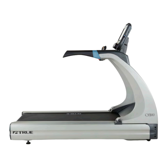
True CS900 Owner's Manual
Treadmill true
Hide thumbs
Also See for CS900:
- Owner's manual (134 pages) ,
- Owner's manual (101 pages) ,
- Owner's manual (143 pages)

Subscribe to Our Youtube Channel
Related Manuals for True CS900


Summary of Contents for True CS900
- Page 1 * Assembly Guide & Warranty Card Included CS900 TREADMILL OWNER’S MANUAL Revision 122313...
- Page 2 CS900 TREADMILL OWNERS MANUAL IMPORTANT: All Products shown are prototype. Actual product delivered may vary. Product specifications, features & software are subject to change without notice. For the most up to date owner’s manual please visit www.truefitness.com. For documents in additional languages please visit www.truefitness.com/document-library/29/international-manuals IMPORTANTE: Todos los productos mostrados son prototipos.
- Page 3 The proud manufacturing tradition of quality and the culture of innovation at TRUE have given rise to a full line of truly extraordinary treadmills, indoor cycles and elliptical cross-trainers. As a result, people all over the world are benefiting from the TRUE experience.
-
Page 4: Table Of Contents
CS900 TREADMILL OWNERS MANUAL TABLE OF CONTENTS : Chapter 1: Safety Instructions Chapter 4B: Escalate Operation Safety Instructions Escalate 9 Overview Use of Safety Key Console Navigation Space Requirements Advanced Console Functions Grounding Instructions Power Requirements Chapter 4C: Emerge Operation... -
Page 5: Chapter 1: Safety Instructions
45, smokes, has high cholesterol, is obese or has not exercised regularly in the past year. Additionally, TRUE recommends consulting a fitness professional on the correct use of this product. - Page 6 To disconnect, turn power OFF at the ON/OFF switch if applicable, then remove plug from electrical outlet. • Never operate a TRUE product if it has a damaged power cord or electrical plug, or if it has been dropped, damaged, or even partially immersed in water. Contact TRUE Customer Service for a replacement.
- Page 7 CHAPTER 1: SAFETY INSTRUCTIONS CAUTION (continued): • Use correct ergonomic positioning while running on treadmill. • Do not allow animals on or near the equipment while in operation. • Use the side handrails whenever additional stability is required. In case of emergency, such as tripping, the side handrails should be grabbed and the user should place his/her feet on the side platforms.
-
Page 8: Use Of Safety Key
SPACE REQUIREMENTS: Space Requirements: TRUE’s recommendation is to leave a minimum of 20” (0.5m) on each side of the treadmill and a 79” (2 m) safety zone at the rear of the treadmill. (See Fig 1) Truefitness.com / 800.426.6570 / 636.272.7100... -
Page 9: Grounding Instructions
CHAPTER 1: SAFETY INSTRUCTIONS GROUNDING INSTRUCTIONS: This product must be grounded, if it should malfunction or breakdown, grounding provides a path of least resistance for electric current to reduce the risk of electric shock. This product is equipped with a cord having an equipment-grounding conductor and a grounding plug. -
Page 10: Power Requirements
CHAPTER 1: SAFETY INSTRUCTIONS Truefitness.com / 800.426.6570 / 636.272.7100... -
Page 11: Warning Decals
CHAPTER 1: SAFETY INSTRUCTIONS WARNING DECALS: WARNING: Replace warning labels that may be worn, damaged or missing To replace any worn or missing warning decals contact TRUE FITNESS by visiting www.truefitness.com or contact customer service at 800-883-8783. COMPLIANCES: This equipment complies with all applicable codes and regulations. For a complete list of compliances, please visit www.truefitness.com. -
Page 12: Chapter 2: Assembly Instructions
Important Electrical Requirements – 120V: Your TRUE treadmill requires a dedicated 120 volt, alternating current (AC), 20 amp grounded outlet circuit. This means nothing else can be plugged into the same circuit. Most power circuits are rated for this 120V AC 20 amp requirement, but you must ensure the treadmill does not share the circuit with anything else. -
Page 13: Pre-Assembly Checklist
CHAPTER 2: ASSEMBLY INSTRUCTIONS PRE-ASSEMBLY CHECK LIST: Item Description Console Rack Frame Pedestal (L) Pedestal (R) Handrail (L) Handrail (R) Hand Grip Assembly (L) Hand Grip Assembly (R) Hand Grip Base Cover Console Cover Truefitness.com / 800.426.6570 / 636.272.7100... - Page 14 CHAPTER 2: ASSEMBLY INSTRUCTIONS PRE-ASSEMBLY CHECK LIST (continued): Item Description Spring Washer 3/8˝ Screw 3/8˝-16UNCx115mm Screw 3/8˝-16UNCx20mm Inner tooth washer M8 Screw 5/16˝-24UNFx38mm Allen hex washer screw 1/4˝-20UNCx20mm Round head Philips screw M4xP0.7x12 Washer Ø6xØ19x1.5t Screw M5xP0.8x20 Motor Cover Plug Screw 1/4˝-20UNFx16mm Spring Washer 1/4˝...
-
Page 15: Assembly Steps
CHAPTER 2: ASSEMBLY INSTRUCTIONS TREADMILL ASSEMBLY STEPS: CAUTION: • Use caution when assembling treadmill. Unpacking and assembling of this treadmill is a two person task. • Remove all treadmill components from packaging. Step 1 Remove Motor Cover: a) Remove the screw (i) and washer (h) from the motor cover and set to the side. b) Remove the motor cover from the treadmill frame (B) Truefitness.com / 800.426.6570 / 636.272.7100... - Page 16 CHAPTER 2: ASSEMBLY INSTRUCTIONS TREADMILL ASSEMBLY STEPS (continued): Step 2 Pedestal Installation: a) Place a section of cardboard onto right straddle cover as shown in Fig 2-2. b) Install Pedestal – R (D) into Frame (B) rotated down and rest the top of the pedestal on the straddle cover as shown below.
- Page 17 CHAPTER 2: ASSEMBLY INSTRUCTIONS TREADMILL ASSEMBLY STEPS (continued): Important Display Specification: Verify on customer product order what type of display will be installed on this TCS900 or TCS900X treadmill. Listed below are the five display options for these series of treadmills. Find the correct Display Option for assembly and follow frame cable routing (step 3) directions for either section 3-2A or 3-2B and for console cable connections (step 13) follow section 13A or 13B Transcend...
- Page 18 CHAPTER 2: ASSEMBLY INSTRUCTIONS TREADMILL ASSEMBLY STEPS (continued): Step 3 Frame Cable Connections: *Use the following installation steps to route the cables in the treadmill frame. Determine which console option will be paired with this unit prior to Step 3-3. If this unit will be paired with a touchscreen console or a 15”TFT console follow step 3-3A.
- Page 19 CHAPTER 2: ASSEMBLY INSTRUCTIONS TREADMILL ASSEMBLY STEPS (continued): Step 3-2A Auxiliary Power Supply, AUXPS (auxiliary power supply cable), & CTRL (data cable): *TOUCHSCREEN CONSOLES & 15” TFT CONSOLES ONLY Separate the two AUXPS (A) cables in the cable bundle and cut the zip ties (B) that connect the female end to the CTRL cable (the male connector is not used for this installation and should remain tied to the CTRL cable).
- Page 20 CHAPTER 2: ASSEMBLY INSTRUCTIONS TREADMILL ASSEMBLY STEPS (continued): Step 3-2A (continued) *TOUCHSCREEN CONSOLES & 15” TFT CONSOLES ONLY 120V Treadmill ONLY: Install Auxiliary Power Supply (included 3-2A-4 in the console box), to the frame incline tower with two large wire ties through the slots as show for this in photo 3-2A-4 to the left and use wire ties to restrain excess power supply cable as shown.
- Page 21 CHAPTER 2: ASSEMBLY INSTRUCTIONS Step 3-2B CTRL (data cable) & AUXPS Power Supply Cable (console power cable): *LED CONSOLES & 9” TFT CONSOLES ONLY Route the CNTRL/AUXPS Cable bundle through the cutout in 3-2B-1 the first incline tower plate as shown in photo 3-2B-1 to the left Continue to route the CNTRL/AUXPS Cable bundle through the 3-2B-2 cutout in the second incline tower plate as shown in photo 3-2B-2...
- Page 22 CHAPTER 2: ASSEMBLY INSTRUCTIONS TREADMILL ASSEMBLY STEPS (continued): Frame Cable Routing Diagram: Once all parts of step 3 are complete, the treadmill frame wiring should resemble the diagram below. Touchscreen & 15” TFT 9”TFT & 2 Window LED AUXPS COAX & COMM COAX &...
- Page 23 CHAPTER 2: ASSEMBLY INSTRUCTIONS TREADMILL ASSEMBLY STEPS (continued): Step 4 Pedestal hardware and Motor Cover: a) Using 7/32 inch hex key, install, but do not tighten, two per side of Bolt 3/8-16 UNC x 4-1/2 (b) and Washer 3/8 Split (a) into front of Frame and through Pedestals as shown below. b) Install Motor Cover using hardware;...
- Page 24 CHAPTER 2: ASSEMBLY INSTRUCTIONS TREADMILL ASSEMBLY STEPS (continued): Step 5 Hand Grip Assemblies: Connect the wires coming from the bottom of the hand grip assemblies (G, H) to the corresponding wires located in the pedestal arms (D, C) as shown in figure 5-1. Secure the hand grip assemblies (G, H) to the pedestal arms (D, C) with four screws (k) and four spring washers (l) on each side.
- Page 25 CHAPTER 2: ASSEMBLY INSTRUCTIONS TREADMILL ASSEMBLY STEPS (continued): Step 6 Separate Console Rack: Remove the screws from the bottom of the console rack and set them to the side. Separate the upper and lower console rack covers as shown to the below. Lower console rack cover Screw Screw...
- Page 26 CHAPTER 2: ASSEMBLY INSTRUCTIONS TREADMILL ASSEMBLY STEPS (continued): Step 8 Console Rack and Secure Pedestals: a) Install Console Rack (A) onto Pedestals R & L by resting Console Rack tubing on top of Pedestal tubing cradles. CAUTION: Do not pinch cabling during this step. b) Using 3/16 inch hex key, install, but do not tighten, eight Bolts 5/16-24 UNF x 1-1/2 (e) and external tooth washers M8 (d) through Pedestal tubing nest and into Console Rack.
- Page 27 CHAPTER 2: ASSEMBLY INSTRUCTIONS TREADMILL ASSEMBLY STEPS (continued): Step 9 Console Rack Cable Connections and Lower Cover Installation: Connect all wires from the right pedestal arm to the wires from the upper console rack cover (A) as shown in figure 9-1(all cables will be connected regardless of console option). *Do not over torque the coax TV cable.
- Page 28 CHAPTER 2: ASSEMBLY INSTRUCTIONS TREADMILL ASSEMBLY STEPS (continued): Step 10 Handrail Installation: a) Insert Handrails (E, F) into Pedestals by slightly rotating Handrail and pushing front rubber lip of Handrail under the Pedestal plastic. b) Secure Handrails with Bolt 1/4– 20 UNF x 3/4 bolts (f, 2 per side) using 7/16 inch socket with extension and ratchet.
- Page 29 CHAPTER 2: ASSEMBLY INSTRUCTIONS TREADMILL ASSEMBLY STEPS (continued): Step 11 Safety Key: a) Safety key and attachment cord are wrapped around plate during shipping. b) Unwind safety key and cord from plate. c) Attach Safety Key magnet to front of console rack as shown below. d) Attach Safety Key clip to plate located on Console Rack (when not working out).
- Page 30 CHAPTER 2: ASSEMBLY INSTRUCTIONS TREADMILL ASSEMBLY STEPS (continued): Step #13A Console Cable Connections: *Follow Step 13A if installing a touchscreen console or 15”TFT console. For other consoles, proceed to Step 13B. 16” Touchscreen 15” TFT 10” Touchscreen Console Console Console Power Cable Network Do Not Use...
- Page 31 CHAPTER 2: ASSEMBLY INSTRUCTIONS TREADMILL ASSEMBLY STEPS (continued): Step #13A Console Cable Connections (continued): *Follow Step 13A if installing a touchscreen console or 15”TFT console. For other consoles, proceed to Step 13B. 16” Touchscreen 15” TFT 10” Touchscreen Console Console Console Do Not Use Ensure the Ground Cable is...
- Page 32 CHAPTER 2: ASSEMBLY INSTRUCTIONS TREADMILL ASSEMBLY STEPS (continued): Step 13B Console Cable Connections: *Follow Step 13B if installing a 9” TFT console or an LED console. For other consoles, return to Step 13A. 9” TFT Console Orange LED Console Connect Data Cable (50-pin) Both 9”...
- Page 33 CHAPTER 2: ASSEMBLY INSTRUCTIONS TREADMILL ASSEMBLY STEPS (continued): Step 14 Rear Console Cover Installation: Once Console is installed, using a Phillips screwdriver, install Rear Console Cover (J) with 3 screws M4 x 10mm (g) CAUTION: Make sure cabling is NOT pinched during installation. Truefitness.com / 800.426.6570 / 636.272.7100...
- Page 34 Power Inlet TV Cable Fixing Base Fig. 11-1: CS900 Treadmill Front Electrical Panel (120V shown) NOTE: 230V Front Electrical Panel will appear different from above. Circuit Breaker is not visible and is within Power Switch. POWER SWITCH: 1 = ON, 0 = OFF CIRCUIT BREAKER: In the event the current drawn by the treadmill exceeds a specified threshold value, the Circuit Breaker will operate;...
-
Page 35: Wiring Schematic
CHAPTER 2: ASSEMBLY INSTRUCTIONS TREADMILL ASSEMBLY STEPS (continued): Wiring Schematic: Optional Decline Foot Assembly Installation: a) Position cardboard from packaging next to side of base unit. b) Using 2 people, tilt treadmill on one side so that cardboard protects side of unit. c) While one person holds treadmill securely in place, the other person must unscrew both rear leveling feet. -
Page 36: Chapter 3: Product Overview
CHAPTER 3: PRODUCT OVERVIEW TREADMILL OVERVIEW: Quick Access Keys Contact Heart Contact Heart Rate Pad Rate Pad Console Assembly Safety (E-Stop) Straddle Covers Belt Belt Adjustment Bolts On/Off Switch, Circuit Breaker, and Leveling Feet Power Cord Truefitness.com / 800.426.6570 / 636.272.7100... -
Page 37: Console Assembly
CHAPTER 3: PRODUCT OVERVIEW TREADMILL OVERVIEW (continued): Console Assembly: The console allows the user to set up a workout program and control the treadmill during a workout (For console overview and operation instructions refer to chapter 4). Quick Access Keys: Allows the user to quickly start, stop and wake the treadmill or make fast, convenient adjustments to the incline level or speed of the treadmill. -
Page 38: Chapter 4: Programming & Operation
CHAPTER 4: PROGRAMMING & OPERATION CAUTION: The safety key must be in place on the treadmill console, and should be attached to the user’s clothing. The treadmill will not operate if the safety key is not attached to the console. HEART RATE MONITORING: This treadmill can monitor a user’s heart rate using either a Polar®... -
Page 39: Heart Rate Control
HEART RATE CONTROL (HRC): Introduction: You are now the owner of the most sophisticated Heart Rate Control treadmill available. TRUE HRC is unique and patented. It accommodates users from rehabilitation to world class athletes, and all those in between. TRUE HRC allows users to do a completely hands free heart rate controlled workout using speed, incline or both. -
Page 40: Program Descriptions
CHAPTER 4: PROGRAMMING & OPERATION HEART RATE CONTROL (continued): Heart Rate Control Stage: The treadmill takes control of speed and incline, keeping the user’s heart rate within a few bpm of their target. When using the Interval HRC Workout, the treadmill alternates between work and rest intervals. Cool-Down: At the end of the workout time or distance, the treadmill reduces the workout intensity by half and goes back into Manual Control mode, where users directly control their cool-down. -
Page 41: Quick Start
CHAPTER 4: PROGRAMMING & OPERATION PROGRAM DESCRIPTIONS (continued): Quick Start: *** A workout in which the user controls all settings. The workout continues until it is ended by the user. Manual: *** Users enter their weight, workout time or distance. The user controls both the SPEED and INCLINE of the treadmill throughout the workout. - Page 42 CHAPTER 4: PROGRAMMING & OPERATION PROGRAM DESCRIPTIONS (continued): Walk and Run Intervals: *** Uses SPEED to create WALKING then RUNNING intervals in 1-minute segments. Users can make adjustments to the INCLINE during the workout. INCLINE changes are permanent; SPEED changes affect the current 1-minute segment only.
- Page 43 CHAPTER 4: PROGRAMMING & OPERATION PROGRAM DESCRIPTIONS (continued): HRC Target: *** Users choose their target heart rate. The treadmill begins in MANUAL control – The user should gradually increase the workout intensity until heart rate is within 10 bpm of their target. At this point, the treadmill takes over to control speed and incline to maintain heart rate within a few beats of the user’s target.
- Page 44 CHAPTER 4: PROGRAMMING & OPERATION PROGRAM DESCRIPTIONS (continued): Air Force fitness Test: * 1.5-mile running test measured against age and gender calculations. Users can make adjustments to the SPEED during the workout. Navy Fitness Test: * 1.5-mile running test measured against age and gender calculations. Users can make adjustments to the SPEED during the workout.
-
Page 45: Virtual Active Videos
CHAPTER 4: PROGRAMMING & OPERATION VIRTUAL ACTIVE VIDEOS: * *Content is provided by Virtual Active™ and is subject to change without notice. Indoor Cycling Group World Tour Northern Italy: Northern Italy is a cyclist’s dream, where stunning views meet tough terrain. The rugged cliffs along Italy’s largest lake, Lago di Garda are just a short ride away from the idyllic small town of Pregasina, and the rural mountain passes of Gampenjoch are as beautiful as they are treacherous. - Page 46 CHAPTER 4: PROGRAMMING & OPERATION VIRTUAL ACTIVE VIDEOS (continued): American Southwest 2 Run: Return to the crimson cliffs of the Southwest. Scale Angel’s Landing in Zion National Park in Utah, surf “The Wave” in Arizona, and go all-in, with a sprint down the fabulous Las Vegas Strip in Nevada. The guided workout begins with a quick build and maintains a strong pace throughout.
-
Page 47: Chapter 4A: Transcend Operation
CHAPTER 4A: TRANSCEND OPERATION TRANSCEND OVERVIEW: Cooling Fan Touchscreen Display Auxiliary LCD Reading Rack Display iPod® Connector Warning Decal USB Jack Headphone Jack Truefitness.com / 800.426.6570 / 636.272.7100... - Page 48 CHAPTER 4A: TRANSCEND OPERATION CONSOLE OVERVIEW (continued): Touchscreen Display: A capacitive touchscreen used for workout control and feature navigation. iPod® Connector: Standard 30 pin iPod connector used to connect an iPod to the console. Headphone Jack: Standard 3.5mm audio jack used to connect headphones to the console during media playback. USB Jack: Allows users to export workout data to an external USB drive or update the console software.
-
Page 49: Touchscreen Introduction
Because of this, capacitive touchscreens are highly responsive and do not require pressure to register a touch. TOUCHSCREEN NAVIGATION: TRUE recommends that users familiarize themselves with the different screens to ensure that they are safely taking advantage of all of the features that this equipment has to offer. Icon Character Map This console uses several icons to provide users with a simplified and visually appealing workout experience. - Page 50 CHAPTER 4A: TRANSCEND OPERATION TOUCHSCREEN NAVIGATION (continued): Home Screen: The Home Screen is displayed on the console when there is no workout in progress. From this screen the user is able to select from various options to begin a workout or view media. A) Quick Start Starts a Quick Start workout in which the user controls all settings.
- Page 51 CHAPTER 4A: TRANSCEND OPERATION TOUCHSCREEN NAVIGATION (continued): Selecting a Preset Workout: Preset workouts are accessed by touching the Workout Finder Button on the home screen. Workouts are organized into 5 categories. To view the workouts in a category simply touch a Category Selection button (A) or swipe through categories in the category preview window (B).
- Page 52 CHAPTER 4A: TRANSCEND OPERATION TOUCHSCREEN NAVIGATION (continued): Workout View Screens: During any workout a Workout View Screen will be displayed to give the user a comprehensive visual overview of their current workout data. A) Custom Data Display #1: This display will toggle between data points throughout the workout. To select which data points are displayed, press the arrow below the Data Display to open the Selection Toolbox (A1) B) Incline: Displays the current incline level.
- Page 53 CHAPTER 4A: TRANSCEND OPERATION TOUCHSCREEN NAVIGATION (continued): Workout View Screen Controls: The Workout View Screens contain controls that allow users to adjust settings during their workout A) Incline/Speed Adjustment Keypads: These keypads allow the user to input a manual speed or inline adjustments. Touching the Keypad Icons (A1) will open these keypads C) Quick Keys: These keys are displayed by touching the Show/Hide button (B) and allow the user to quickly switch between preset...
- Page 54 CHAPTER 4A: TRANSCEND OPERATION TOUCHSCREEN NAVIGATION (continued): Switching Between Workout View Screens: There are several Workout Data Screens available to choose from. To switch between screens the user can touch the button selector (A) for the specific Workout Data Screen they wish to use or simply swipe their finger across the main display window (B) to scroll through the available screens.
-
Page 55: Ipod® Integration
CHAPTER 4A: TRANSCEND OPERATION iPod® INTEGRATION: The Transcend console has an advanced iPod® Integration feature which allows a user to connect their iPod® to the console via the 30 pin connector located on the front of the console. Once connected, the user can control the functions of their iPod®... -
Page 56: Tv Controls
CHAPTER 4A: TRANSCEND OPERATION TV CONTROLS: This console has an integrated HDTV Tuner which allows the user to watch live programming in crisp, clear high Definition. The TV controls are built in to a Workout View Screen to allow the user to monitor their workout while enjoying their favorite shows. -
Page 57: Virtual Active
CHAPTER 4A: TRANSCEND OPERATION VIRTUAL ACTIVE®: Virtual Active® provides users with a scenic, first-person video to enhance a workout. Audio from TV and iPod® sources can be combined with this feature for a truly unique workout. Additionally, The Workout View Screen controls and displays are still available when using this feature in standard mode. -
Page 58: Advanced Console Functions
Entering Service Mode: Entering Service Mode can be completed by pressing and holding the TRUE logo (A) in the upper left corner of the home screen. When the word “TRUE” (B) begins to flash, release the logo and press and hold the lower right corner of the screen(C). - Page 59 CHAPTER 4A: TRANSCEND OPERATION ADVANCED CONSOLE FUNCTIONS (continued): Summary Screen: The Summary Screen will be the first screen displayed after entering service mode. This screen will give a general overview of the unit’s setup. A) Product Model: The model number that the console is currently configured to. B) Product Type: Specifies if the console is configured for a treadmill, bike or elliptical.
- Page 60 CHAPTER 4A: TRANSCEND OPERATION ADVANCED CONSOLE FUNCTIONS (continued): Setup Menu: The setup menu is accessed by touching the Setup button on the main menu. The Setup Menu is separated into seven sub- categories and allows to users configure the console and to set up various functions of the unit. Sub-Categories can be accessed by touching the selection buttons...
- Page 61 CHAPTER 4A: TRANSCEND OPERATION ADVANCED CONSOLE FUNCTIONS (continued): Setup Menu - Calibration: Calibration will conduct a basic test of the drive and incline systems to ensure that they are operating as intended. Calibration may also be used by technicians to troubleshoot system faults. WARNING: This process will take full control of the treadmill and can be dangerous if caution is not taken.
- Page 62 CHAPTER 4A: TRANSCEND OPERATION ADVANCED CONSOLE FUNCTIONS (continued): Setup Menu - Clock: Correctly setting up the clock will ensure that all workout data that is exported by a user will be correctly labeled. Correct time is also important for troubleshooting purposes when viewing the system’s error log. Setting the Clock: •...
- Page 63 CHAPTER 4A: TRANSCEND OPERATION ADVANCED CONSOLE FUNCTIONS (continued): Setup Menu - Screen Saver: Users can load JPG images to be used by the console as a custom screen saver. In order to be uploaded to the console, images will need to be placed on a USB drive in a folder named “screen saver” (case sensitive). Importing Screen Saver Images: •...
- Page 64 CHAPTER 4A: TRANSCEND OPERATION ADVANCED CONSOLE FUNCTIONS (continued): Setup Menu - Facility Images: The Transcend console supports customizable facility images to help promote specials, events or endorse a brand. In order to be uploaded to the console, images will need to be placed on a USB drive in a folder named “facility” (case sensitive). Importing Screen Saver Images: •...
- Page 65 CHAPTER 4A: TRANSCEND OPERATION ADVANCED CONSOLE FUNCTIONS (continued): Setup Menu - TV Setup: Transcend consoles have an integrated HDTV Tuner which allows the user to watch live programming in crisp, clear high Definition. Before any programming can be viewed, the TV signal needs to be set up. (TV Options will not be displayed on the Home Screen or in the Workout Data Screens until the TV Setup Steps have been completed) TV Setup Steps: •...
- Page 66 CHAPTER 4A: TRANSCEND OPERATION ADVANCED CONSOLE FUNCTIONS (continued): Setup Menu - TV Setup Steps (continued): • When the console is finished scanning for channels, the Channel List (G) will be populated with the available channels. Individual channels can be removed by touching the channel in the Channel List (G) and then touching the Remove Channel button (H) or all Channels can be cleared by touching the Clear All Channels button (I).
- Page 67 CHAPTER 4A: TRANSCEND OPERATION ADVANCED CONSOLE FUNCTIONS (continued): Setup Menu - Network Setup: The Network Setup screen displays the current network information for the console (A) and allows for Netpulse® configuration (in a Netpulse® enabled environment), To Configure Netpulse®: • From the Main Menu, press the Setup button.
- Page 68 CHAPTER 4A: TRANSCEND OPERATION ADVANCED CONSOLE FUNCTIONS (continued): Options Menu: The Options menu allows users to customize settings on the console to meet their needs. The settings in this menu save automatically. A) Metric Units: When enabled, the console will display all Metric units rather than American Standard. B) Save Workout Enabled: Turn on this feature to allow users to export workout data to USB devices.
- Page 69 CHAPTER 4A: TRANSCEND OPERATION ADVANCED CONSOLE FUNCTIONS (continued): Timers Menu: The Timers Menu allows for time limits to be set on various console features and functions. A) Cooldown Time: Use the slider to adjust the length of the cooldown segment at the end of a workout. B) Maximum Workout Time: This setting will limit the amount of time that all workouts can last (this setting does not apply to quickstart workouts, manual workouts or distance workouts).
- Page 70 CHAPTER 4A: TRANSCEND OPERATION ADVANCED CONSOLE FUNCTIONS (continued): Statistics Menu: The statistics menu provides an overview of how and how long the unit has been used. Touching the summary button (A) will provide a usage summary. Run Hours (B) is the total number of hours the unit has been used. Machine Distance (C) is the total distance in miles that the belt has traveled.
-
Page 71: Diagnostics Menu
CHAPTER 4A: TRANSCEND OPERATION ADVANCED CONSOLE FUNCTIONS (continued): Diagnostics Menu: The Diagnostics Menu contains tools used to help diagnose errors and performance issues. The first screen Displayed is Tests: A) Contact Heart Rate: Ensures the unit is receiving the data by displaying the user’s heart rate when the contact heart rate pads are gripped. B) Telemetry Heart Rate: Use a wireless heart rate strap or simulator to test if the unit is receiving wireless heart rate data. - Page 72 .deb file on a blank USB drive (as shown) and follow the steps on the next page: WARNING: To avoid errors and console damage, all files or documents on the USB stick, other than the TRUE software update, must be placed in a folder.
- Page 73 CHAPTER 4A: TRANSCEND OPERATION ADVANCED CONSOLE FUNCTIONS (continued): Diagnostics Menu - Software Update (continued) • Insert the USB drive containing the software update into the console’s USB port. • From the Main Menu, press the Diagnostics button. • From the Diagnostics Menu, press Software update button button (A). •...
- Page 74 CHAPTER 4B: ESCALATE OPERATION ESCALATE OVERVIEW: LCD Display Selection Buttons Selection Buttons Incline Speed Keys Keys Start Stop Reading Warning Rack Decal 30 Pin iPod® Numeric USB Port Headphone Connector Keypad Jack Truefitness.com / 800.426.6570 / 636.272.7100...
-
Page 75: Chapter 4B: Escalate Operation
CHAPTER 4B: ESCALATE OPERATION ESCALATE OVERVIEW (continued): LCD Display: Used to monitor or control a work out and feature navigation. Selection Keys: Used to navigate menus and make selections via the LCD Display. Incline Keys: Manually increases or decreases the incline of the treadmill. Start: Allows the user to begin a Quick Start workout or preset workout. -
Page 76: Console Navigation
CHAPTER 4B: ESCALATE OPERATION CONSOLE NAVIGATION: Home Screen: The Home Screen is displayed on the console when there is no workout in progress. From this screen the user is able to select from various options to begin a workout. A) Workout Finder Displays preset workout selections by category B) Quick Start Starts a Quick Start workout in which the user controls all settings until the workout is ended by the user. - Page 77 CHAPTER 4B: ESCALATE OPERATION CONSOLE NAVIGATION (continued): Selecting a Preset Workout: Preset workouts are accessed by selecting Workout Finder from the home screen. To view the workouts in a category, select the category (A) by using the Scroll Selection Buttons (B) and then press the Next Selection Button (C). *Press and hold the Next Selection Button to return to the previous screen.
- Page 78 CHAPTER 4B: ESCALATE OPERATION CONSOLE NAVIGATION (continued): Workout Data Screens: During any workout a Workout Data Screen will be displayed to give the user a comprehensive visual overview of their current workout data. A) Custom Data Display #1: By Default, this display will show the distance for the current workout. Users can also choose custom data points to be seen in this display.
- Page 79 CHAPTER 4B: ESCALATE OPERATION CONSOLE NAVIGATION (continued): Workout Data Screen Controls: The Workout Data Screens contain various controls that allow users to adjust workout settings and to customize their overall workout experience. These controls are accessed by pressing the Selection Button for the control they wish to use. A) Change View: Switches between the available Workout Data Screens B) Cool Down:...
- Page 80 CHAPTER 4B: ESCALATE OPERATION CONSOLE NAVIGATION (continued): D) Source: Toggles between available audio sources which include; iPod® (when connected via the 30 pin iPod connector), TV (if your console is equipped with a Broadcast Vision receiver), and FM radio. When an audio source is selected the user is given control over volume (A), and channel adjustments (B).
- Page 81 CHAPTER 4B: ESCALATE OPERATION CONSOLE NAVIGATION (continued): F) Show Tools: Pressing the Show Tools Selection Button (A) will display various options. Pressing the Change Data Selection Button (C) will toggle the data points in Custom Data Display 1(1) between distance and pace. The data in custom data display 2 (2) will toggle between calories and METs.
-
Page 82: Advanced Console Functions
CHAPTER 4B: ESCALATE OPERATION ADVANCED CONSOLE FUNCTIONS: Entering Service Mode: Entering Service Mode can be completed by pressing and holding the upper left selection button (A) for 3-5 seconds or until the “Workout Finder” icon (B) blinks. When the “Workout Finder” icon blinks, release and hold the “Workout Finder”... - Page 83 CHAPTER 4B: ESCALATE OPERATION ADVANCED CONSOLE FUNCTIONS (continued): Summary Screen: The Summary Screen provides an overview of the unit’s current settings (values cannot be changed in this screen). A) Product Model: The model number that the console is currently configured to. B) Software Version: The current version of software that is installed on the console.
- Page 84 Utilities Menu - Product Setup: The product setup screen allows the technician to adjust model configuration, incline range, and speed range. TRUE’s recommendation is to only use the Setup Wizard to adjust these attributes. After pressing the Setup Wizard Selection...
- Page 85 To complete the update, press the update selection button (A). WARNING: To avoid errors and console damage, All files or documents on the USB stick, other than the TRUE software update, must be placed in a folder.
- Page 86 CHAPTER 4B: ESCALATE OPERATION ADVANCED CONSOLE FUNCTIONS (continued): Utilities Menu - B-Vision Setup: When equipped with the optional Broadcast Vision receiver, the Escalate console is capable of playing audio wirelessly from video sources that are equipped with a Broadcast Vision compatible wireless transmitter. To configure this feature, follow the steps below.
- Page 87 CHAPTER 4B: ESCALATE OPERATION ADVANCED CONSOLE FUNCTIONS (continued): Utilities Menu - B-Vision Setup (continued): 3. Plug headphones into the headphone jack on the console and wear them for the remaining steps. 4. Use the Channel Selection Buttons (D) to scroll through the available channels. 5.
-
Page 88: Heart Rate Priority
CHAPTER 4B: ESCALATE OPERATION ADVANCED CONSOLE FUNCTIONS (continued): Options Menu: The options menu contains 12 Settings with various options available for each. For a complete list of settings and options, please refer to the table on the next page. To navigate the options menu, use the scroll selection buttons (A) to highlight the option to be changed (B) and use the speed keys (C) or incline keys (D) to adjust the options. -
Page 89: Pause Time
CHAPTER 4B: ESCALATE OPERATION ADVANCED CONSOLE FUNCTIONS (continued): Options Menu (continued): Max Workout Time: This setting will limit the amount of time that all workouts can last. By choosing the “Off” setting, the time will be unlimited (this setting does not apply to manual workouts or distance workouts). Finder Timeout: Choose how long the Workout Finder remains on the screen without any user interaction. - Page 90 CHAPTER 4B: ESCALATE OPERATION ADVANCED CONSOLE FUNCTIONS (continued): Diagnostics Menu - Calibration/Test: This menu contains tools for testing and verifying treadmill operation. A) Key Test: When a key is pressed on the console “NONE” will change to indicate which key is being pressed. In the event of a stuck key, the key that is being engaged will display (the selection buttons are excluded from this test).
- Page 91 CHAPTER 4B: ESCALATE OPERATION ADVANCED CONSOLE FUNCTIONS (continued): Diagnostics Menu - Error Log: Error codes are an important part of troubleshooting any issues with the treadmill. Any time an error occurs it is entered into the error log for review by a service professional. This console is capable of storing the ten most recent errors. The error log can be cleared by pressing the enter selection button (A), but it is not recommended.
-
Page 92: Chapter 4C: Emerge Operation
CHAPTER 4C: EMERGE OPERATION EMERGE OVERVIEW: Incline LED Upper LED Lower LED Speed LED Display Display Display Display Incline Speed Keys Keys Start Stop Reading Warning Rack Decal USB Port Workout Enter HRC Cruise Finder Control Truefitness.com / 800.426.6570 / 636.272.7100... - Page 93 CHAPTER 4C: EMERGE OPERATION EMERGE OVERVIEW (continued): Incline Keys: Manually increases or decreases the incline of the treadmill. Start: Allows the user to begin a Quick Start workout or preset workout. Reading Rack: A ledge on the console can be used to hold a book, magazine, e-reader, or tablet computer during a workout. USB Port: Allows users to export workout data to an external USB drive or update the console software.
-
Page 94: Console Navigation
CHAPTER 4C: EMERGE OPERATION CONSOLE NAVIGATION: Selecting a Preset Workout: To begin a preset workout, press the Workout Finder button (A) until the desired program is shown in the Upper LED Display (B) and then press the Enter button (C). *To begin a Target HRC Workout, press the HRC Cruise Control button (D) followed by the Enter button (C) Workout Data Entry: Before beginning a preset workout, the console will ask the user for information in order to give more accurate workout... -
Page 95: Workout Summary
CHAPTER 4C: EMERGE OPERATION CONSOLE NAVIGATION (continued): Workout Summary: Workouts can be ended by the user pressing the Stop button (A) or by completing the time or distance in a preset workout. Once a workout has ended the console will display a workout Summary which will give the user an overview of their workout which includes;... -
Page 96: Advanced Console Functions
CHAPTER 4C: EMERGE OPERATION ADVANCED CONSOLE FUNCTIONS: Entering Maintenance Mode: Press and Hold the UP Incline Button (A) until the unit beeps (about 3 seconds). Then release the UP Incline Key and Immediately press and hold the Enter Button (B) until the unit beeps again (about 3 seconds). Then release the Enter button and when the Upper LED Display (C) reads “Maintenance Mode”, press the Enter Button (B) to enter maintenance mode. - Page 97 CHAPTER 4C: EMERGE OPERATION ADVANCED CONSOLE FUNCTIONS (continued): Maintenance Mode Navigation (continued): Within a category users can scroll through available options using the UP and DOWN Incline Keys (A). Once the desired setting is shown in the Upper LED Display (B), press the Enter Button (C) to confirm the selection. After confirming the selection, the + and –...
- Page 98 CHAPTER 4C: EMERGE OPERATION ADVANCED CONSOLE FUNCTIONS (continued): Diagnostics: The diagnostics menu contains various settings as well as tools used to help diagnose errors and performance issues. Total time: Displays an accumulative count of the total number of hours the unit has been used. Sound: Toggles the sound on or off.
-
Page 99: Display Test
WARNING: Misconfiguration of the console may cause damage to the unit and void the manufacturer warranty. If necessary, please contact TRUE Fitness Technical Support at 800-883-8783 for assistance. Model: Used to make changes to the model to which the console is installed. -
Page 100: Chapter 5: Care & Maintenance
CAUTION: Do not use any acidic cleaners. Doing so will weaken the paint or powder coatings and may void the TRUE Fitness Warranty. Never pour water or spray liquids on any part of the treadmill. Allow the treadmill to dry completely before using. -
Page 101: Running Belt Alignment
If you hear any chafing or the running belt appears to be getting damaged, stop the running belt immediately by pressing the STOP key. Contact the TRUE Service Department. Walk around to the rear of the unit and observe the belt for a few minutes. -
Page 102: Tensioning The Running Belt
Turn the treadmill on and start the belt and check if the slipping continues. Repeat the above steps if additional adjustment is necessary. TREADMILL LUBRICATION: For commercial use over 20 hours per week, TRUE recommends lubricating every three months. • Loosen the belt adjustment bolts in the rear end caps. •... -
Page 103: Leveling The Treadmill
OTHER SCHEDULED PREVENTIVE MAINTENANCE: TRUE recommends that quarterly scheduled maintenance be performed by a qualified service technician. Please contact your dealer or visit www.truefitness.com to contact a local TRUE authorized service technician. Scheduled Preventive Maintenance: Record time, distance and hours from the console. -
Page 104: Chapter 6: Customer Service
HOURS OF OPERATION: 8:30 A.M. - 5:00 P.M. CST E-MAIL: service@truefitness.com CONTACTING SALES: Interested in TRUE Products? Please contact us with any sales or product inquires so that we may direct you to the appropriate sales representative to answer your questions. TRUE FITNESS HOME OFFICE 865 HOFF ROAD ST. -
Page 105: Reporting Freight Claims Or Parts Damage
Severe Damage: Obvious damage to external packaging / internal product. Please refuse the shipment and it will be returned to TRUE Fitness by the carrier. Contact the TRUE Fitness customer support team by calling 800.883.8783 or sales support team by calling 800.426.6570 Monday-Friday during normal business hours to notify us that the shipment has been refused. -
Page 106: Chapter 7: Additional Information
This troubleshooting guide is intended to assist in diagnostics only and is not all inclusive. Technical specifications, error codes and programming are subject to change without notice. TRUE accepts no liability for any damage or loss suffered by persons whom rely wholly or in part on any description or statement contained within this manual. Please visit www.TRUEfitness.com to obtain the most recent version of all manuals and contact the TRUE Service Department at 800-... - Page 107 Corrupted brainboard Corrupted Re-install Console configuration - fails integrity Firmware and software Console software/firmware check versions are not Configuration Contact dealer or TRUE compatible service Console Configure Power cycle incorrectly Re-configure console Fault CN01: Re-install Console Math error - software...
- Page 108 CHAPTER 7: ADDITIONAL INFORMATION TROUBLESHOOTING GUIDE (CONTINUED): Fault CN03: Membrane Key stuck Membrane key is Contact dealer or TRUE Console Stuck Key down/closed damaged service Power cycle Loose Cable Fault CN04: Check cable connections Lower Board Brainboard fails to receive timely...
- Page 109 CHAPTER 7: ADDITIONAL INFORMATION TROUBLESHOOTING GUIDE (CONTINUED): Lubricate treadbelt High Belt Deck Friction Contact dealer or TRUE service Fault SP01: Belt Tread motor rpm is below target Check drive belt and Speed High belt tension Under Speed walking belt Tension...
- Page 110 Run incline calibration Incline Incline operating range - may indicate Max/Min that it is disconnected. Incline Potentiometer Contact dealer or TRUE value out of range service Fault A101: Power cycle Motor AC MCB 2.5 VDC Ref Status Motor Control Board...
- Page 111 CHAPTER 7: ADDITIONAL INFORMATION TROUBLESHOOTING GUIDE (CONTINUED): Dirty or misaligned Contact dealer or TRUE speed sensor service Fault A111: Lubricate treadbelt Motor AC MCB Illegal Speed Command High Belt Deck Friction Contact dealer or TRUE Controller Fault service Low Line Voltage...
- Page 112 TROUBLESHOOTING GUIDE (CONTINUED): Loose Cable Connection Check cable connections Fault A121: Motor AC MCB Phase A High Gate Driver Fault Drive Motor Contact dealer or TRUE Controller Fault service Loose Cable Connection Check cable connections Fault A122: Motor AC MCB Phase B High Gate Driver Fault...
- Page 113 Run incline calibration Fault SC02: Smart Incline Potentiometer Incline Stall Incline Stall Card value out of range Contact dealer or TRUE Acme Nut Jammed service motor bearings Power cycle Console displays Fault Calibration not saved. Check cable connections Incline disabled.
-
Page 114: Product Specifications
P r e m i u m F i t n e s s E q u i p m e n t S i n c e 1 9 8 1 With the CS900 treadmill, you not only get high-quality craftsmanship and durability, you get over 30 years of history in the treadmill manufacturing industry. - Page 115 Standard Belt Siegling Multi-Ply with PVC Coating Rollers 3.5" (9 cm) w/ Sealed Bearings Impact System True Soft System Frame Construction Robotically Welded Heavy-Gauge Steel Lubrication Silax Speed Range 0.5 to 12.0 MPH; (0.8 to 19.3 km/H; 0.8 to 24.1 km/H) 0.5 to 15.0 MPH with decline option...
-
Page 116: Warranty Information
Product. The frame is warranted for labor and freight (for parts dealer, then TRUE Limited Warranty service may be obtained shipped from TRUE) for three years from date of purchase. * by contacting TRUE directly at: This limited warranty on structural frame does not include TRUE Fitness, Service Department paint or coatings. - Page 117 CS900 TREADMILL SERIAL NUMBERS: Registration Form is completed on-line; or if the attached form is filled in, signed by the original purchaser and mailed to TRUE within 30 days of purchaser’s receipt of this Product. The serial The CS900 treadmill comes with two serial numbers; one on number must be intact on the Product for this Limited Warranty the base and one on the display console (see diagram below).
- Page 118 CS900 Treadmill Thank you for purchasing a TRUE product. To validate the TRUE product warranty the fast and easy way, please go on-line now to truefitness.com/support and register your product. The information you provide will never be distributed to any other individuals or agencies for any purpose.
Need help?
Do you have a question about the CS900 and is the answer not in the manual?
Questions and answers