
Related Manuals for Belden HIRSCHMANN MSP30


Summary of Contents for Belden HIRSCHMANN MSP30
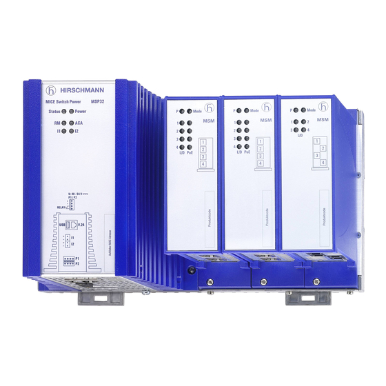
- Page 1 User Manual Installation MICE Switch Power - MSP30/32/40/42 MICE Switch Media modules - MSM20/22/24/40/42/46/50/60 Installation MSP/MSM Technical support Release 15 04/2023 https://hirschmann-support.belden.com...
- Page 2 The naming of copyrighted trademarks in this manual, even when not specially indicated, should not be taken to mean that these names may be considered as free in the sense of the trademark and tradename protection law and hence that they may be freely used by anyone. ©...
-
Page 3: Table Of Contents
Contents Important information Safety instructions About this manual Description General device description 1.1.1 Basic device 1.1.2 Media modules Device name and product code Device views 1.3.1 Basic device 1.3.2 Media modules Number of ports and connections Power supply 1.5.1 Supply voltage with characteristic value C 1.5.2 Supply voltage with the characteristic value P SFP Transceiver Ethernet ports... - Page 4 1.10 Input/output interfaces 1.10.1 Signal contact 1.10.2 Digital input Installation Checking the package contents Installing the SD card (optional) Installing and grounding the device 2.3.1 Installing the device onto the DIN rail 2.3.2 Mounting on a flat surface 2.3.3 Grounding the device Connecting the terminal blocks 2.4.1 Supply voltage with characteristic value C 2.4.2 Supply voltage with the characteristic value P...
- Page 5 Monitoring the ambient air temperature Upgrading Software Maintenance and service Disassembly Removing an SFP transceiver (optional) Removing a media module 7.2.1 Device variants featuring customer-specific version with the characteristic value HH 7.2.2 Device variants featuring customer-specific version with the characteristic value HX Removing the device 7.3.1 Device variants featuring customer-specific version with the characteristic value HH...
- Page 6 Scope of delivery, order numbers and accessories Scope of delivery Accessories Underlying technical standards Further support Installation MSP/MSM Release 15 04/2023...
-
Page 7: Important Information
Important information Note: Read these instructions carefully, and familiarize yourself with the device before trying to install, operate, or maintain it. The following notes may appear throughout this documentation or on the device. These notes warn of potential hazards or call attention to information that clarifies or simplifies a procedure. - Page 8 NOTICE NOTICE provides information about procedures that do not involve the risk of injury. Installation MSP/MSM Release 15 04/2023...
-
Page 9: Safety Instructions
Safety instructions WARNING UNCONTROLLED MACHINE ACTIONS To avoid uncontrolled machine actions caused by data loss, configure all the data transmission devices individually. Before you start any machine which is controlled via data transmission, be sure to complete the configuration of all data transmission devices. Failure to follow these instructions can result in death, serious injury, or equipment damage. - Page 10 Qualification requirements for personnel Only allow qualified personnel to work on the device. Qualified personnel have the following characteristics: Qualified personnel are properly trained. Training as well as practical knowledge and experience make up their qualifications. This is the prerequisite for grounding and labeling circuits, devices, and systems in accordance with current standards in safety technology.
- Page 11 Device casing Only technicians authorized by the manufacturer are permitted to open the casing. Never insert pointed objects (narrow screwdrivers, wires, etc.) into the device or into the connection terminals for electric conductors. Do not touch the connection terminals. ...
- Page 12 Requirements for connecting the supply voltage The following requirements apply without restrictions: All of the following requirements are complied with: The supply voltage corresponds to the voltage specified on the type plate of the device. The power supply conforms to overvoltage category I or II. ...
- Page 13 CE marking The labeled devices comply with the regulations contained in the following European directive(s): 2011/65/EU and 2015/863/EU (RoHS) Directive of the European Parliament and of the Council on the restriction of the use of certain hazardous substances in electrical and electronic equipment.
- Page 14 22. The UKCA conformity declaration will be available to the relevant authorities at the following address: Belden UK Ltd. 1 The Technology Centre, Station Road Framlingham, IP13 9EZ, United Kingdom You find the UKCA conformity declaration as PDF file for downloading on the Internet at: https://www.doc.hirschmann.com/certificates.html...
- Page 15 Supplier's Declaration of Conformity 47 CFR § 2.1077 Compliance Information MSP30/32/40/42 and MSM20/22/24/40/42/46/50/60 U.S. Contact Information Belden – St. Louis 1 N. Brentwood Blvd. 15th Floor St. Louis, Missouri 63105, United States Phone: 314.854.8000 This device complies with part 15 of the FCC Rules. Operation is subject...
- Page 16 Recycling note After usage, this device must be disposed of properly as electronic waste, in accordance with the current disposal regulations of your county, state, and country. The following approvals are only in place for the media modules MSM20/22/24/40/42 in connection with a MSP30/32/40/42 basic device: Relevant for use as industrial switching equipment ...
- Page 17 WARNING – EXPLOSION HAZARD – Substitution of any components may impair suitability for Class I, Division 2. – Apply Control Drawing No. 000172843DNR for installation and use of the MSP basic devices. You find further information on the following pages. –...
- Page 18 Hazardous Location Class I, Ordinary Location, Non-Hazardous Division 2, Groups A, B, C, D Area, Non-explosive Atmosphere MSP30 MSP32 THE RELAY TERMINALS ARE DE- PENDENT UPON THE FOLLOWING 30 V 90 mA 5 nF 1 μH For use in Hazardous Locations Class I, Division 2, Groups A, B ,C ,D: Only allowed for MSP30/32 model numbers which are individually labelled: “FOR USE IN HARDOUS LOCATIONS”...
- Page 19 Installation MSP/MSM Release 15 04/2023...
- Page 20 Installation MSP/MSM Release 15 04/2023...
- Page 21 ATEX directive 2014/34/EU – specific regulations for safe operation In Ex zone 2, only devices with a corresponding label may be operated. When operating the devices and modules in Ex zone 2, the following applies: MICE Switch Power MSP30 and MSP32: II 3 G Ex ec nC IIC T4 Gc DEKRA 13ATEX0090 X...
- Page 22 Provisions shall be made to prevent the rated voltage from being exceeded by transient disturbances of more than 119 V. If an SD card is used, it has to be secured with a thumb screw. For information about the position on the device see “View from above”...
- Page 23 When the temperature under rated conditions exceeds +70 °C (+158 °F) at the cable or at conduit entry point, or +80 °C (+176 °F) at the branching point of the conductors, take measures so that the temperature specification of the selected cable is in compliance with the actual measured temperature values.
-
Page 24: About This Manual
About this manual The “Installation” user manual contains a device description, safety instructions, a description of the display, and the other information that you need to install the device. The following manuals are available as PDF files for download on the Internet https://www.doc.hirschmann.com/ ... -
Page 25: Key
The symbols used in this manual have the following meanings: Listing Work step Subheading Installation MSP/MSM Release 15 04/2023... -
Page 26: Description
Description General device description The device is designed for the special requirements of industrial automation. The device meets the relevant industry standards, provides very high operational reliability, even under extreme conditions, and also long-term reliability and flexibility. The device allows you to set up switched Industrial Ethernet networks according to standard IEEE 802.3. -
Page 27: Device Name And Product Code
The characteristic values stand for specific product properties. You have numerous options of combining the device characteristics. You can determine the possible combinations using the configurator which is available in the Belden Online Catalog https://catalog.belden.com on the web page of the device. - Page 28 Item Characteristic Characte Description ristic value 9 ... 10 Number: (exclusively 4 × /100/1000 Mbit/s ports /100/1000 MSP30/32) Mbit/s ports (exclusively 8 × + 4 × 1000/2500 Mbit/s ports MSP40/42) 2 × 1000/10000 Mbit/s ports 16 × + 4 × 1000/2500 Mbit/s ports 2 ×...
- Page 29 Item Characteristic Characte Description ristic value Software configuration Entry (Hirschmann Standard) Diagnostic User (DBDEW) Ethernet/IP Profinet 21 ... 22 Software level HiOS Layer 2 Advanced HiOS Layer 3 Advanced 23 ... 27 Software version 06.0. Software version 06.0 XX.X Current software version Table 1: Device name and product code a.
- Page 30 Media modules Item Characteristic Characteristic Description value 1 ... 3 Product MICE Switch Media Module Data rate /100 Mbit/s Ports /100/1000 Mbit/s ports 1000/2500 Mbit/s ports 1000/10000 Mbit/s ports Hardware type 0 Standard Suitable for PoE or PoE+ Suitable for I/O operation suitable for PoE or PoE+ with external power supply (hyphen) 7 ...
- Page 31 Item Characteristic Characteristic Description value Hardware none configuration Software Entry (Hirschmann Standard) configuration 22 ... 26 Software 99.9 Without software version Table 2: Device name and product code a. Exclusively for twisted pair connections. b. Exclusively use SFP transceivers with the “EEC” extension, otherwise the standard temperature range applies.
- Page 32 Certifications Application case Certificates and Characteristic value declarations MSP30/32 MSP40/42 MSM20 MSM22 MSM24 MSM40 MSM42 MSM46 MSM50 MSM60 Standard applications ATEX Zone 2 — — — — — T9, TY, U9, UW, UX, UY, V9, VT, VU, VY, W9, WY, X9, Y9, Z9 IEC 60950-1 T9, TY, U9, UW, UX, UY, V9, VT, VU, VY, W9, WY, X9, Y9, Z9 EN 61131-2...
-
Page 33: Device Views
Device views 1.3.1 Basic device Front view 11 11 Slot for the SD card Thumb screw LED display elements for device status Slot 1 for media modules Slot 2 for media modules Slot 3 for media modules Locking gate for removing the device Backplane (Basic device MSP30/32/40/42) Power module... - Page 34 LED display elements for device status Slot 1 for media modules Slot 2 for media modules Slot 3 for media modules Backplane (Basic device MSP30) Power module (Basic device MSP30) Grounding screw Terminal block, V.24 interface, USB interface, signal contacts Fastening hole Table 5: Front view (using the example MSP30-0804..HX...)
- Page 35 View from below 11 11 Connection for 2 digital inputs USB interface The device supports the ACA22 starting with the software version 3.0. V.24 interface LED display elements are not functional in the existing device version. Slot 3 for media modules Slot 2 for media modules Slot 1 for media modules Positioning bar...
- Page 36 View from above Slot for the SD card Thumb screw Backplane (Basic device MSP30/32/40/42) Power module (Basic device MSP30/32/40/42) Slot 1 for media modules Slot 2 for media modules Slot 3 for media modules Female multipoint connector Table 7: View from above (using the example MSP30/32-0804..HH...) Note: On the basic device MSP40/42, the media module slot 1 is coded differently from the other slots.
-
Page 37: Media Modules
Power module (Basic device MSP30) Backplane (Basic device MSP30) Slot 1 for media modules Slot 2 for media modules Slot 3 for media modules Table 8: View from above (using the example MSP30-0804..HX...) 1.3.2 Media modules Media modules MSM20 Port 1 (F/O) Port 2... - Page 38 Port 1 (F/O) Port 2 (F/O) Port 3 (Twisted Pair) Port 4 (Twisted Pair) Table 10: MSM20-S2S2T1T1... Port 1 (F/O) Port 2 (F/O) Port 3 (F/O) Port 4 (F/O) Table 11: MSM20-S4S4S4S4... Port 1 (Twisted Pair) Port 2 (Twisted Pair) Port 3 (Twisted Pair) Port 4...
- Page 39 Media modules MSM40 Port 1 (Twisted Pair) Port 2 (Twisted Pair) Port 3 (Twisted Pair) Port 4 (Twisted Pair) Table 13: MSM40-T1T1T1T1... Port 1 (F/O) Port 2 (F/O) Port 3 (F/O) Port 4 (F/O) Port 1 (Twisted Pair) Port 2 (Twisted Pair) Port 3 (Twisted Pair)
- Page 40 PoE-capable media modules MSM22, MSM42 and MSM46 Port 1 (Twisted Pair) Port 2 (Twisted Pair) Port 3 (Twisted Pair) Port 4 (Twisted Pair) Table 15: MSM22-T5T5T5T5... Port 1 (Twisted Pair) Port 2 (Twisted Pair) Port 3 (Twisted Pair) Port 4 (Twisted Pair) Table 16: MSM42-T1T1T1T1...
- Page 41 The PoE ports allow the connection and remote supply of, for example, IP telephones (Voice over IP), webcams, sensors, printer servers and WLAN access points. With PoE, power is supplied to these terminal devices through the twisted pair cable. The PoE support complies with the following technical standards: Standard Description IEEE 802.3af...
- Page 42 MSM24 I/O media module Figure Item Function Input (I) Input Output (O) Output Auxiliary voltage Table 20: MSM24-IOIOIOIO... The MSM24 I/O module has 4 electrically insulated digital inputs and outputs according to the technical standard EN 61131-2. Through these inputs, the I/O module receives and transmits digital sensor signals.
- Page 43 Signal, terminal Function OFF-1 NC contact, channel 1 CENTER-1 Center contact, channel 1 ON-1 NO contact, channel 1 OFF-2 NC contact, channel 2 CENTER-2 Center contact, channel 2 ON-2 NO contact, channel 2 OFF-3 NC contact, channel 3 CENTER-3 Center contact, channel 3 ON-3 NO contact, channel 3 OFF-4...
- Page 44 Media modules MSM50 and MSM60 Port 1 SFP slot Port 2 SFP slot Port 3 SFP slot Port 4 SFP slot Table 24: MSM50-Q6Q6Q6Q6... The media module MSM50-Q6Q6Q6Q6... has 4 SFP slots for 1/2.5 Gbit/ s F/O connections (connection via SFP transceivers). Port 1 SFP slot Port 2...
- Page 45 Note: MSP40 or MSP42 basic devices exclusively support the full range of functions of MSM60 media modules starting with software version 7.5.01 or higher. You find the latest software version on the Internet on the Hirschmann product pages at www.hirschmann.com. Installation MSP/MSM Release 15 04/2023...
-
Page 46: Number Of Ports And Connections
Number of ports and connections Depending on their variant, the basic devices offer you the following number of slots for media modules and the following maximum amount of connectable network segments: Basic device Total Number of Number of Max. number of Max. - Page 47 Slots MSP30/32-0804... MSP40/42-0012... /100/1000 Mbit/s 1000/2500 Mbit/s 1000/10000 Mbit/s /100 Mbit/s /100/1000 Mbit/s /100 Mbit/s /100/1000 Mbit/s a. Exclusively for twisted pair connections. Slots MSP30/32-1604... MSP40/42-0020... /100/1000 Mbit/s 1000/2500 Mbit/s 1000/10000 Mbit/s /100 Mbit/s /100/1000 Mbit/s /100 Mbit/s /100/1000 Mbit/s /100 Mbit/s /100/1000 Mbit/s /100 Mbit/s...
-
Page 48: Power Supply
Power supply 1.5.1 Supply voltage with characteristic value C For the redundant supply of the device, 2 4-pin terminal blocks are available. See “Supply voltage with characteristic value C” on page 66. 1.5.2 Supply voltage with the characteristic value P For the redundant supply of the device, 2 4-pin terminal blocks are available. - Page 49 Autopolarity In addition, the MSM22 media module allows you to use Power over Ethernet (PoE) according to IEEE 802.3af and Power over Ethernet Plus (PoE+) according to IEEE 802.3at. The PoE power is supplied via the wire pairs transmitting the signal (phantom voltage).
- Page 50 10/100/1000 Mbit/s twisted pair port This port is an RJ45 socket. The 10/100/1000 Mbit/s twisted pair port allows you to connect network components according to the IEEE 802.3 10BASE-T/100BASE-TX/ 1000BASE-T standard. This port supports: 10 Mbit/s half-duplex mode, 10 Mbit/s full duplex mode ...
-
Page 51: Display Elements
The 100/1000 Mbit/s F/O port allows you to connect network components according to the IEEE 802.3 100BASE-FX/1000BASE-SX/1000BASE-LX standard. 100 Mbit/s half-duplex mode, 100 Mbit/s full duplex mode 1000 Mbit/s full duplex Delivery state: 100 Mbit/s full duplex when using a Fast Ethernet SFP transceiver ... -
Page 52: Device Status
1.8.1 Device status These LEDs provide information about conditions which affect the operation of the whole device. Status Power Display Color Activity Meaning Power Supply voltage — none Supply voltage is too low yellow lights up Device variants with redundant power supply: Supply voltage 1 or 2 is on flashes 4 ×... -
Page 53: Digital Input
Display Color Activity Meaning Storage medium — none ACA storage medium not connected green lights up ACA storage medium connected flashes 3 × a Device writes to/reads from the storage period medium yellow lights up ACA storage medium inoperative 1.8.2 Digital input Status Power... -
Page 54: Msm20 Media Modules
1.8.3 MSM20 media modules Power Mode L/D L/D Figure 1: MSM20 media modules: display elements (front view) Display Color Activity Meaning Power Supply voltage — none Media module is inoperative green lights up Voltage supply to the media module is on Mode Device status —... -
Page 55: Msm40 Media Modules
1.8.4 MSM40 media modules Power Mode L/D L/D Figure 2: MSM40 media modules: display elements (front view) Display Color Activity Meaning Power Supply voltage — none Media module is inoperative green lights up Voltage supply to the media module is on Mode Device status —... -
Page 56: Msm22, Msm42 And Msm46 Media Modules
1.8.5 MSM22, MSM42 and MSM46 media modules Power Mode L/D PoE Figure 3: MSM22, MSM42 and MSM46 media modules: display elements (front view) Display Color Activity Meaning Power Supply voltage — none Media module is inoperative green lights up Voltage supply to the media module is on Voltage supply to the PoE port is on yellow lights up... -
Page 57: Msm50 Media Modules
1.8.6 MSM50 media modules Power Mode L/D L/D Figure 4: MSM50 media modules: display elements (front view) Display Color Activity Meaning Power Supply voltage — none Media module is inoperative green lights up Voltage supply to the media module is on Mode Device status green... -
Page 58: Msm60 Media Modules
1.8.7 MSM60 media modules Power Mode Figure 5: MSM60 media modules: display elements (front view) Display Color Activity Meaning Power Supply voltage — none Media module is inoperative green lights up Voltage supply to the media module is on Mode Device status green lights up... -
Page 59: Msm24 I/O Media Module
1.8.8 MSM24 I/O media module Power Figure 6: MSM24 I/O media modules: display elements (front view) Display Color Activity Meaning Power Supply voltage — none The I/O module is not operating. green lights up The voltage supply to the I/O module is Device status —... -
Page 60: Management Interfaces 1.9.1 V.24 Interface (External Management)
Management interfaces 1.9.1 V.24 interface (external management) A serial interface is provided on the RJ45 socket (V.24 interface) for the local connection of an external management station (VT100 terminal or PC with corresponding terminal emulation). This gives you the option to set up a connection to the Command Line Interface (CLI) and to the system monitor. -
Page 61: Usb Interface
On the front of the device there is an LED display that informs you about the status of the interface. 1.9.3 USB interface Note: Applies to approval DNV: Note that the USB interface of the MSP30/32/40/42 is exclusively for service purposes. -
Page 62: Input/Output Interfaces
1.10 Input/output interfaces 1.10.1 Signal contact Figure Function Connection for the power supply including signal contact Plus terminal of the supply voltage Minus terminal of the supply voltage FAULT FAULT Connection for the power supply including signal contact Plus terminal of the supply voltage Minus terminal of the supply voltage FAULT FAULT... -
Page 63: Installation
Installation The devices have been developed for practical application in a harsh industrial environment. Hirschmann supplies the device ready for operation. Perform the following steps to install and configure the device: Checking the package contents Installing the SD card (optional) ... -
Page 64: Installing And Grounding The Device
Installing and grounding the device WARNING FIRE HAZARD Install the device in a fire enclosure according to IEC 60950-1. Failure to follow this instruction can result in death, serious injury, or equipment damage. CAUTION BURNING HAZARD The surfaces of the device casing may become hot. Avoid touching the device while it is operating. -
Page 65: Mounting On A Flat Surface
Figure 7: Mounting on the DIN rail 2.3.2 Mounting on a flat surface The device variants featuring the customer-specific version with characteristic value HX are suitable for installation on a flat surface. Perform the following work steps: You will find the drilling dimensions for mounting the device in the chapter“Dimension drawings”... -
Page 66: Connecting The Terminal Blocks
Connecting the terminal blocks WARNING ELECTRIC SHOCK Never insert pointed objects (narrow screwdrivers, wires, etc.) into the device or into the connection terminals for electric conductors. Do not touch the connection terminals. Failure to follow these instructions can result in death, serious injury, or equipment damage. -
Page 67: Supply Voltage With The Characteristic Value P
With non-redundant supply of the mains voltage, the device reports a power failure. You can avoid this message by changing the configuration in the management, or, with power supply units of the same type, by feeding the supply voltage in through both inputs. 2.4.2 Supply voltage with the characteristic value P You have the option of supplying the supply voltage redundantly, without... -
Page 68: Signal Contact
2.4.3 Signal contact For every signal contact to be connected, make sure the following requirements are met: The electrical wires are voltage-free. The connected voltage is limited by a current limitation device or a fuse. Observe the electrical threshold values for the signal contact. See “General technical data”... -
Page 69: Installing Terminal Blocks, Switching On The Supply Voltage
Installing terminal blocks, switching on the supply voltage WARNING ELECTRIC SHOCK Connect only a supply voltage that corresponds to the type plate of your device. Failure to follow these instructions can result in death, serious injury, or equipment damage. Use screws to secure the connectors to the device. You find the prescribed tightening torque in chapter: “General technical data”... -
Page 70: Device Variants Featuring Customer-Specific Version With The Characteristic Value Hh
2.7.1 Device variants featuring customer-specific version with the characteristic value HH Perform the following work steps: Remove the protective cap from the slot for the media module on the device. Insert the latch on the bottom of the media module into the opening in the lower positioning bar of the basic device. -
Page 71: Device Variants Featuring Customer-Specific Version With The Characteristic Value Hx
2.7.2 Device variants featuring customer-specific version with the characteristic value HX Perform the following work steps: Remove the protective cap from the slot for the media module on the device. Mount the media module on the slot. Fasten the device with the hardware elements provided by screwing to the basic device. -
Page 72: Connecting An I/O Module
Make sure that the connected supply voltage complies the requirements of IEEE 802.3af or IEEE 802.3at: For the use of type-1-powered devices (PoE): Rated voltage: 48 V DC Max. voltage range: 45 V DC ... 57 V DC For the use of Type 2 Powered Devices (PoE+): Rated voltage: 54 V DC Max. - Page 73 I-GND + 24 V + 24 V − 0 V − 0 V Figure 10: Connection of a sensor with auxiliary voltage supply 1 - Sensor 2 - MSM24 module I-GND + 24 V − 0 V Figure 11: Circuit via auxiliary voltage supply 1 - Switch (2-wire sensor) 2 - MSM24 module ...
-
Page 74: Installing An Sfp Transceiver (Optional)
Installing an SFP transceiver (optional) Prerequisites: Exclusively use Hirschmann SFP transceivers. See “Accessories” on page 108. Figure 12: Installing SFP transceivers: Installation sequence Perform the following work steps: Take the SFP transceiver out of the transport packaging (1). Remove the protection cap from the SFP transceiver (2). ... - Page 75 Note: Verify that you connect only optical ports with the same optical transmission properties with each other. Note: For media modules with M12 sockets: Screw all data cables to the media modules. You find the prescribed tightening torque in chapter: “General technical data”...
-
Page 76: 10/100 Mbit/S Twisted Pair Port
2.10.1 10/100 Mbit/s twisted pair port Further information: See “10/100 Mbit/s twisted pair port” on page 48. Connect the data cables according to your requirements. 2.10.2 10/100/1000 Mbit/s twisted pair port Further information: See “10/100/1000 Mbit/s twisted pair port” on page 50. ... -
Page 77: Basic Settings
Basic Settings The IP parameters must be entered when the device is installed for the first time. The device provides the following options for configuring IP addresses: AutoConfiguration Adapter Input via the HiView or Industrial HiVision application. You find further information about the applications HiView or Industrial HiVision on the Internet at the Hirschmann product pages: HiView... -
Page 78: Monitoring The Ambient Air Temperature
Monitoring the ambient air temperature Operate the device below the specified maximum ambient air temperature exclusively. See “General technical data” on page 85. The ambient air temperature is the temperature of the air at a distance of 5 cm (2 in) from the device. It depends on the installation conditions of the device, for example the distance from other devices or other objects, and the output of neighboring devices. -
Page 79: Upgrading Software
Upgrading Software The upgrade options for MSP30/32/40/42 and MSM20/22/24/40/42/46/50/ 60 device depend on the software level of the device. See “Device name and product code” on page 27. Note: For software version 04.0 or higher, “HiOS” is available as a common software image for all software levels. -
Page 80: Maintenance And Service
Maintenance and service When designing this device, Hirschmann largely avoided using high-wear parts. The parts subject to wear and tear are dimensioned to last longer than the lifetime of the product when it is operated normally. Operate this device according to the specifications. ... -
Page 81: Disassembly
Disassembly Removing an SFP transceiver (optional) Figure 13: De-installing SFP transceivers: De-installation sequence Perform the following work steps: Open the locking mechanism of the SFP transceiver (1). Pull the SFP transceiver out of the slot via the open locking mechanism (2). -
Page 82: Device Variants Featuring Customer-Specific Version With The Characteristic Value Hh
7.2.1 Device variants featuring customer-specific version with the characteristic value HH Perform the following work steps: Disable the supply voltage. Additionally with MSM24/MSM46: Disconnect the terminal block. Disconnect the data cables. Remove the 2 screws. Insert a screwdriver between the female multipoint connector and the media module. -
Page 83: With The Characteristic Value Hx
7.2.2 Device variants featuring customer-specific version with the characteristic value HX Perform the following work steps: Disconnect the data cables. Remove the screws. Pull the media module out of the slot. Removing the device WARNING ELECTRIC SHOCK Disconnect the grounding only after disconnecting all other cables. -
Page 84: Device Variants Featuring Customer-Specific Version With The Characteristic Value Hh
7.3.1 Device variants featuring customer-specific version with the characteristic value HH Perform the following work steps: Disable the supply voltage. Disconnect the data cables. Disconnect the terminal blocks. Disconnect the grounding. Insert a screwdriver horizontally below the casing into the locking gate. ... -
Page 85: Technical Data
Technical data General technical data Basic device Dimensions MSP30/32-0804..HH... See figure 14 on page 90. W × H × D MSP40/42-0012..HH... MSP30/32-1604..HH... See figure 15 on page 91. MSP40/42-0020..HH... MSP30/32-2404..HH... See figure 16 on page 91. MSP40/42-0028..HH... MSP30-0804..HX... See figure 17 on page 92. MSP30-1604..HX... - Page 86 Supply voltage with Rated voltage Device variants with PoE: 48 V DC the characteristic Device variants with PoE 54 V DC value P Plus: Voltage range incl. maximum Device variants with PoE: 45 V DC ... tolerances 57 V DC Device variants with PoE 51 V DC ...
- Page 87 a. The MSP basic devices MSP32 and MSP42 support a PoE power budget of 120 W. You cannot expand the PoE power budget of the basic devices with media modules. b. Temperature of the ambient air at a distance of 5 cm (2 in) from the device c.
-
Page 88: Digital Input
Climatic conditions during Ambient air temperature -40 °C ... +85 °C (-40 °F ... +185 °F) storage Humidity 5 % ... 95 % (non-condensing) Air pressure min. 700 hPa (+3000 m ASL; +9842 ft ASL) max. 1060 hPa (-400 m ASL; -1312 ft ASL) Pollution degree Protection classes... -
Page 89: Digital Output
Digital output Maximum permitted supply voltage max. 60 V DC or max. 30 V AC SELV according to IEC 60950-1 or ES1 according to IEC/EN 62368-1 under UL conditions: max. 30 V DC, ohmic load Maximum current load of relay contacts and terminals 1 A Maximum switching frequency 1 Hz Relay type... -
Page 90: Dimension Drawings
Note: For the pin assignment see “MSM22, MSM42 and MSM46 media modules” on page Dimension drawings Basic device inch 236,6 9.31 Figure 14: MSP30/32-0804..HH..., MSP40/42-0012..HH... Installation MSP/MSM Release 15 04/2023... - Page 91 inch 313,8 12.35 Figure 15: MSP30/32-1604..HH..., MSP40/42-0020..HH... inch 15.39 Figure 16: MSP30/32-2404..HH..., MSP40/42-0028..HH... Installation MSP/MSM Release 15 04/2023...
- Page 92 inch 276,6 10.89 131,3 131,3 5.17 5.17 Figure 17: MSP30-0804..HX... inch 353,8 13.93 120,25 120,3 99,25 4.74 4.73 3.91 Figure 18: MSP30-1604..HX... Installation MSP/MSM Release 15 04/2023...
- Page 93 inch 16.9 5.47 5.47 5.47 Figure 19: MSP30-2404..HX... Media modules inch 38,2 117,8 4.64 Figure 20: Dimensions for media modules with characteristic value HH Installation MSP/MSM Release 15 04/2023...
- Page 94 38,2 117,8 4.64 Figure 21: Dimensions for media module MSM46-T1T1T1T1... with characteristic value HH (with terminal block for external PoE supply voltage) inch 38,2 117,8 4.64 Figure 22: Dimensions for media modules with customer-specific version characteristic value HX Installation MSP/MSM Release 15 04/2023...
-
Page 95: Emc And Immunity
EMC and immunity EMC interference Standard Naval Railway Substation emission applications applications applications applications (trackside) Radiated emission EN 55032 Class A Class A Class A Class A DNV Guidelines — EMC 1 — — FCC 47 CFR Part 15 Class A Class A Class A Class A... - Page 96 EMC interference Standard Naval Railway Substation immunity applications applications applications applications (trackside) EN 61000-4-2 Air discharge ±8 kV ±8 kV ±8 kV ±15 kV IEEE C37.90.3 Electromagnetic field EN 61000-4-3 80 MHz ... 3000 MHz max. 10 V/m max. 10 V/m max.
- Page 97 a. EN 61131-2, CE, FCC – applies to all devices b. Merchant Navy – applies to devices with the approval codes VU, U9, UY, UW, UX c. EN 50121-4 – applies to devices with the certification codes VT, T9, TY d.
-
Page 98: Power Consumption/Power Output
Power consumption/power output The order numbers correspond to the product codes of the devices. See “Device name and product code” on page 27. Device name Maximum power consumption Power output MSP30-0804... 16.0 W 55.0 Btu (IT)/h MSP30-1604... 17.0 W 58.0 Btu (IT)/h MSP30-2404... - Page 99 a. xx = M2, M4, S2, S4, L2, G2 b. FE= Fast Ethernet 100 MBit/s; GE= Gigabit Ethernet 1000 MBit/s Media modules Maximum power output MSM22 62 W MSM42 62 W MSM46 124 W Table 46: Maximum PoE power output Installation MSP/MSM Release 15 04/2023...
-
Page 100: Network Range
Network range Note: The following SFP transceivers exclusively have approvals according to characteristic value Z9: SFP-FAST-MM/LC SFP-FAST-MM/LC EEC SFP-FAST-SM/LC SFP-FAST-SM/LC EEC SFP-GIG-LX/LC... SFP-GIG-BA LX/LC EEC SFP-GIG-BB LX/LC EEC SFP-GIG-BA LX+/LC EEC SFP-GIG-BB LX+/LC EEC ... -
Page 101: Fast Ethernet Sfp Transceiver
8.9.2 Fast Ethernet SFP transceiver Product code Mode Wave length Fiber System Example for F/O line Fiber BLP/Dispersion attenuation length attenuation M-FAST-SFP-MM/LC... 1310 nm 50/125 µm 0 dB ... 8 dB 0 km ... 5 km 1.0 dB/km 800 MHz×km (0 mi ... -
Page 102: Bidirectional Fast Ethernet Sfp Transceiver
8.9.3 Bidirectional Fast Ethernet SFP transceiver Product code Mode Wave length Wave length Fiber System Example for F/O Fiber BLP/Dispersion attenuation line length attenuation SFP-FAST-BA 1310 nm 1550 nm 50/125 µm 0 dB ... 16 dB 0 km ... 2 km 1.0 dB/km 800 MHz×km MM/LC EEC... - Page 103 Product code Mode Wave length Fiber System Example for F/O line Fiber attenuation BLP/Dispersion attenuation length M-SFP-MX/LC... 1310 nm 62.5/125 µm 0 dB ... 12 dB 0 km ... 50 km 1.0 dB/km 500 MHz×km (0 mi ... 31.06 mi) M-SFP-LX/LC...
-
Page 104: Bidirectional Gigabit Ethernet Sfp Transceiver
With F/O adapter compliant with IEEE 802.3-2002 Clause 38 (single-mode fiber offset-launch mode conditioning patch cord). g. With F/O adapter compliant with IEEE 802.3-2002 Clause 38 (single-mode fiber offset-launch mode conditioning patch cord). h. Including 2.5 dB system reserve when compliance with the fiber data is observed. 8.9.5 Bidirectional Gigabit Ethernet SFP transceiver Product code... -
Page 105: Gigabit Ethernet Sfp Transceiver
8.9.6 2.5 Gigabit Ethernet SFP transceiver Product code Mode Wave length Fiber System Example for F/O Fiber BLP/Dispersion attenuation line length attenuation M-SFP-2.5-MM/LC EEC 850 nm 50/125 µm 0 dB ... 4 dB 0.55 km (0.34 mi) 3.5 dB/km 2000 MHz×km (OM3) M-SFP-2.5-MM/LC EEC 850 nm... - Page 106 Product code Mode Wave length Fiber System Example for F/O line Fiber BLP/dispersion attenuation length attenuation M-SFP-10-LR/LC EEC SM 1310 nm 9/125 µm 0 dB ... 7.4 dB 10 km (6.21 mi) 0.4 dB/km 3.5 ps/(nm×km) M-SFP-10-ER/LC EEC LH 1550 nm 9/125 µm 3 dB ...
- Page 107 Scope of delivery, order numbers and accessories Scope of delivery Basic device Amount Article 1 × Basic device 1 × Safety and general information sheet 1 × 4-pin terminal block for digital input 2 × 4-pin terminal block for supply voltage Media modules ...
- Page 108 Accessories Fast Ethernet SFP transceiver Order number M-FAST SFP-TX/RJ45 942 098-001 M-FAST SFP-TX/RJ45 EEC 942 098-002 The following operating conditions apply to twisted pair transceivers: Usable with: - HiOS as of software version 03.0.00 - for PRP ports on RSP devices, as of software version 02.0.01 - for PRP ports on EES devices, as of software version 02.0.02 - Classic switch software as of software version 08.0.00 - HiSecOS as of software version 01.2.00...
- Page 109 Gigabit Ethernet SFP transceiver Order number M-SFP-TX/RJ45 EEC 942 161-001 The following operating conditions apply to twisted pair transceivers: Usable with: - HiOS as of software version 03.0.00 - Classic Switch software, as of software version 04.1.00. - HiSecOS as of software version 01.2.00 Do not use with the following devices: - SPIDER II - MSP/MSM...
- Page 110 2.5 Gigabit Ethernet SFP transceiver Order number M-SFP-2.5-MM/LC EEC 942 162-001 M-SFP-2.5-SM-/LC EEC 942 163-001 M-SFP-2.5-SM/LC EEC 942 164-001 M-SFP-2.5-SM+/LC EEC 942 165-001 10 Gigabit Ethernet SFP+ transceiver Order number M-SFP-10-SR/LC-EEC 942 210-001 M-SFP-10-LR/LC-EEC 942 211-001 M-SFP-10-ER/LC-EEC 942 212-001 M-SFP-10-ZR/LC 942 213-001 Designation Order number...
- Page 111 10 Underlying technical standards Designation CSA C22.2 No. 142 Canadian National Standard(s) – Process Control Equipment Industrial Products EN 50121-4 Railway applications – EMC – Emission and immunity of the signaling and telecommunications apparatus (Rail Trackside) EN 55032 Electromagnetic compatibility of multimedia equipment – Emission Requirements IEC 60950-1 Information technology equipment –...
- Page 112 You find the addresses of our partners on the Internet at http://www.hirschmann.com. A list of local telephone numbers and email addresses for technical support directly from Hirschmann is available at https://hirschmann-support.belden.com. This site also includes a free of charge knowledge base and a software download section. Customer Innovation Center...
- Page 113 Installation MSP/MSM Release 15 04/2023...
Need help?
Do you have a question about the HIRSCHMANN MSP30 and is the answer not in the manual?
Questions and answers