Table of Contents
Advertisement
Quick Links
User Manual
Installation
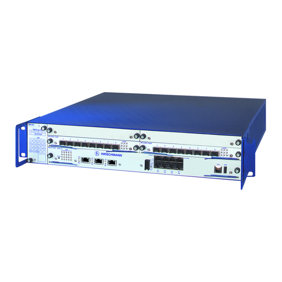
Modular Industrial Ethernet Backbone Switch
MACH4002 family
M4-AIR
M4-FAST 8SFP
1
2
MEDIA SLOTS
3
4
1
2
SLOT.PORT
1
2
LS
DA
LS
DA
M4-8TP-RJ45
LED
P
P1
P2
P3
P4
RM
RL1
RL2
FAN
RUN
MACH 4002 48+4G
LED
L/D
FDX 1000
AN TP/FO
RING
LED
PORT STBY
2
1
TEST
SELECT
MACH4002-24G
M4-AIR
M4-FAST 8SFP
1
2
MEDIA SLOTS
3
4
1
2
SLOT.PORT
1
2
LS
DA
LS
DA
M4-8TP-RJ45
LED
P
P1
P2
P3
P4
RM
RL1
RL2
FAN
RUN
MACH 4002 48+4G
LED
L/D
FDX 1000
AN TP/FO
RING
LED
PORT STBY
2
1
TEST
SELECT
MACH4002-48G
M4-AIR
M4-FAST 8SFP
1
2
MEDIA SLOTS
3
4
1
2
SLOT.PORT
LS
1
DA
LS
2
DA
M4-8TP-RJ45
LED
P
P1
P2
P3
P4
RM
RL1
RL2
FAN
RUN
MACH 4002 48+4G
LED
L/D
FDX 1000
AN TP/FO
RING
LED
PORT STBY
2
1
TEST
SELECT
MACH4002-24G+3X
M4-AIR
M4-FAST 8SFP
1
2
MEDIA SLOTS
3
4
1
2
SLOT.PORT
1
2
LS
DA
LS
DA
M4-8TP-RJ45
LED
P
P1
P2
P3
P4
RM
RL1
RL2
FAN
RUN
MACH 4002 48+4G
LED
L/D
FDX 1000
AN TP/FO
RING
LED
PORT STBY
2
1
TEST
SELECT
MACH4002-48G+3X
Installation MACH4002
Release 16 03/2021
LS/DA
3
4
5
6
7
8
1
4
7
2
5
8
3
6
3
4
5
6
DA LS
7
DA LS
8
LS
DA LS
DA LS
DA LS
DA
6.1
6.2
6.3
6.4
6.5
6.6
LS/DA
3
4
5
6
7
8
1
4
7
2
5
8
3
6
3
4
5
6
7
8
LS
DA LS
DA LS
DA LS
DA LS
DA LS
DA
6.1
6.2
6.3
6.4
6.5
6.6
LS/DA
3
4
5
6
7
8
1
4
7
2
5
8
3
6
LS
3
DA LS
4
DA LS
5
DA LS
6
DA LS
7
DA LS
8
DA
5.1
5.2
5.3
LS/DA
3
4
5
6
7
8
1
4
7
2
5
8
3
6
3
4
5
6
DA LS
7
DA LS
8
LS
DA LS
DA LS
DA LS
DA
5.1
5.2
5.3
M4-FAST 8SFP
1
2
3
4
P
1
2
3
4
LS
DA
LS
DA
LS
DA LS
M4-FAST 8TP-RJ45-PoE
P
LS/DA 6.1
RL1
RL2
6.7
6.8
6.1
6.3
6.5
6.7
6.2
6.4
6.6
6.8
M4-FAST 8SFP
1
2
3
4
P
1
2
3
4
LS
DA
LS
DA
LS
DA LS
M4-FAST 8TP-RJ45-PoE
P
LS/DA 6.1
RL1
RL2
6.7
6.8
6.1
6.3
6.5
6.7
6.2
6.4
6.6
6.8
M4-FAST 8SFP
1
2
3
4
P
LS
1
DA
LS
2
DA
LS
3
DA LS
4
M4-FAST 8TP-RJ45-PoE
P
LS/DA 6.1
RL1
RL2
6.1
6.3
6.5
6.7
6.2
6.4
6.6
6.8
M4-FAST 8SFP
1
2
3
4
P
1
2
3
4
LS
DA
LS
DA
LS
DA LS
M4-FAST 8TP-RJ45-PoE
P
LS/DA 6.1
RL1
RL2
6.1
6.3
6.5
6.7
6.2
6.4
6.6
6.8
LS/DA
5
6
7
8
1
4
7
2
5
8
P
3
6
5
6
DA LS
7
DA LS
8
DA LS
DA LS
DA
R
V.24
USB
LS/DA
5
6
7
8
1
4
7
2
5
8
P
3
6
5
6
7
8
DA LS
DA LS
DA LS
DA LS
DA
R
6.16 LS/DA
V.24
USB
6.9
6.11
6.13
6.15
6.10
6.12
6.14
6.16
LS/DA
5
6
7
8
1
4
7
2
5
8
P
3
6
DA LS
5
DA LS
6
DA LS
7
DA LS
8
DA
R
V.24
USB
LS/DA
5
6
7
8
1
4
7
2
5
8
P
3
6
5
6
DA LS
7
DA LS
8
DA LS
DA LS
DA
R
6.16 LS/DA
V.24
USB
6.9
6.11
6.13
6.15
6.10
6.12
6.14
6.16
Technical support
https://hirschmann-support.belden.com
Advertisement
Table of Contents

Related Manuals for Belden Hirschmann MACH4002 Series


Summary of Contents for Belden Hirschmann MACH4002 Series
- Page 1 DA LS DA LS M4-8TP-RJ45 M4-FAST 8TP-RJ45-PoE MACH 4002 48+4G LS/DA 6.1 6.16 LS/DA FDX 1000 AN TP/FO V.24 RING PORT STBY TEST SELECT 6.11 6.13 6.15 6.10 6.12 6.14 6.16 MACH4002-48G+3X Installation MACH4002 Technical support Release 16 03/2021 https://hirschmann-support.belden.com...
- Page 2 The naming of copyrighted trademarks in this manual, even when not specially indicated, should not be taken to mean that these names may be considered as free in the sense of the trademark and tradename protection law and hence that they may be freely used by anyone. ©...
-
Page 3: Table Of Contents
Contents Important Information Safety instructions About this manual Description General device description MACH4002 Basic Device Supply voltage 1.3.1 Power supply connections on the rear side of the device 1.3.2 M4-POWER power unit chassis 1.4.1 M4-AIR plug-in fan 1.4.2 Monitoring temperature and fan Integrated basic board 1.5.1 Left area of basic board 1.5.2 Right area of basic board... - Page 4 1.10.2 Port status display 1.10.3 ACA Auto Configuration Adapter Installation Checking the package contents Installing the device and grounding 2.2.1 Selecting the assembly location 2.2.2 Mounting on a flat surface 2.2.3 Mounting in a switch cabinet 2.2.4 Grounding the device Mounting the power supply unit on the back of the MACH4002 device Mounting the power unit chassis, connecting with the...
- Page 5 EMC and immunity Network range 6.5.1 10/100/1000 Mbit/s twisted pair port 6.5.2 Fast Ethernet SFP transceiver 6.5.3 Bidirectional Fast Ethernet SFP transceiver 6.5.4 Gigabit Ethernet SFP transceiver 6.5.5 Bidirectional Gigabit Ethernet SFP transceiver Power consumption/power output Scope of delivery 6.7.1 MACH4002-... 6.7.2 M4-POWER 6.7.3 M4-S-...
-
Page 6: Important Information
Important Information Notice: Read these instructions carefully, and look at the equipment to become familiar with the device before trying to install, operate, or maintain it. The following special messages may appear throughout this documentation or on the equipment. The message warns of potential hazards or calls attention to information that clarifies or simplifies a procedure. -
Page 7: Safety Instructions
Safety instructions General safety instructions You operate this device with electricity. Improper usage of the device entails the risk of physical injury or significant property damage. The proper and safe operation of this device depends on proper handling during transportation, proper storage and installation, and careful operation and maintenance procedures. - Page 8 The complete defective plug-in power supply unit must be changed. For safety reasons, the fuse installed in the plug-in power supply units may not be changed. Only switch on the device when the housing is closed. Close all empty slots with a covering panel.
- Page 9 cable is connected, the basic device is grounded via the power supply connection. Only now do you take the card out of the conductive bag. Outside the basic device, only store the cards in a conductive ESD protective bag. ESD protective field equipment is available for the safe handling of electrostatically endangered assemblies.
- Page 10 The internal workings of the basic device are not for users! Do not reach inside a switched-on device because of the danger caused by high energy densities. When fully equipped with media modules, the device weighs up to 10 kg.
- Page 11 CE marking The devices comply with the regulations contained in the following European directives: 2011/65/EU and 2015/863/EU (RoHS) Directive of the European Parliament and of the Council on the restriction of the use of certain hazardous substances in electrical and electronic equipment.
- Page 12 Supplier's Declaration of Conformity 47 CFR § 2.1077 Compliance Information MACH4002 U.S. Contact Information Belden – St. Louis 1 N. Brentwood Blvd. 15th Floor St. Louis, Missouri 63105, United States Phone: 314.854.8000 This device complies with part 15 of the FCC Rules. Operation is subject...
-
Page 13: About This Manual
About this manual The “Installation” user manual contains a device description, safety instructions, a description of the display, and the other information that you need to install the device. The following manuals are available as PDF files for download on the Internet https://www.doc.hirschmann.com/ ... -
Page 14: Key
The symbols used in this manual have the following meanings: Listing Work step Subheading Installation MACH4002 Release 16 03/2021... -
Page 15: Description
Description General device description The modular, industry-compatible MACH4002 Gigabit Ethernet system is used as an industrial backbone system, and also in applications with high data volumes, such as Voice/Video over IP. The MACH4002 is a modular, industry-compatible Gigabit Ethernet system in a 19"... -
Page 16: Mach4002 Basic Device
MACH4002 Basic Device LS/DA LS/DA M4-AIR M4-FAST 8SFP M4-FAST 8SFP MEDIA SLOTS SLOT.PORT DA LS DA LS DA LS DA LS DA LS DA LS DA LS DA LS DA LS DA LS M4-8TP-RJ45 M4-FAST 8TP-RJ45-PoE MACH 4002 48+4G LS/DA 6.1 6.16 LS/DA FDX 1000 AN TP/FO... - Page 17 Media module 1 (plug-in unit), Port 1.1 ... 1.8, 10/100/1000 Mbit/s Media module 2 (plug-in unit), Port 2.1 ... 2.8, 10/100/1000 Mbit/s Basic board (integrated), Port 6.1 ... 6.8, RJ45 10/100/1000 Mbit/s Table 2: Ports and Media module slots on the MACH4002-24G LS/DA LS/DA M4-AIR...
- Page 18 Basic device Maximum number of ports on the device, in brackets number of installed ports on the basic Maximum number of media board modules TP ports, 10/100 Mbit/s TP ports, 10/100/ TP/SFP Combo ports, XFP slots, 10 Gbit/s 10/100 Mbit/s 10/100/1000 Mbit/s 1000 Mbit/s 10/100/1000 Mbit/s 4002-24G...
- Page 19 Depending on the device variant, a basic device has 2 or 4 slots for media modules (media modules 1 ... 2 or 1 ... 4) that are hot-swappable and provide 8 Fast Ethernet/Gigabit Ethernet ports each. The media modules differ with regard to the number of interfaces and the media type for connecting segments.
-
Page 20: Supply Voltage
Supply voltage On the back of the device there is a slot for a power supply unit (AC or DC) and 2 inputs for the redundant power supply via the M4-POWER power supply unit basic device. Both inputs are uncoupled. Figure 1: Back side of the MACH4002 basic device 1 - M4-POWER connection (voltage input P3-1/P3-2, external) 2 - M4-POWER connection (voltage input P4-1/P4-2, external) -
Page 21: Power Supply Connections On The Rear Side Of The Device
1.3.1 Power supply connections on the rear side of the device Power supply plug-in units for switch basic device MACH4002 M4-S-AC/DC 300W See “Order numbers/product description” on page 65. Note: The plug-in power units of the M4-POWER power supply basic device cannot be used for the switch basic device. - Page 22 Figure 2: M4-POWER power unit chassis, front side of the device (mounting with up to 3 power units) 1 - Power unit 1 2 - Power unit 2 3 - Power unit 3 Figure 3: M4-POWER power unit chassis, back side of the device Installation MACH4002 Release 16 03/2021...
- Page 23 Power supply plug-in units for power supply basic device M4-POWER M4-P-AC/DC 300W (see on page 65 “Order numbers/product description”). Note: The plug-in power units of the M4-POWER power supply basic device cannot be used for the switch basic device. Note: Note the safety instructions in “General safety instructions”...
- Page 24 M4-AIR MEDIA SLOTS SLOT.PORT FDX 1000 AN TP/FO RING PORT STBY TEST PoE M4-AIR Figure 4: Fan supply plug-in unit M4-AIR: Side view and front view 1.4.2 Monitoring temperature and fan Fan monitoring Every individual fan sends a speed-dependent signal to the basic system. The fan monitoring displays the failure of one or more individual fans.
- Page 25 Recommendation for temperature monitoring Use the following table (based on half speed for all fans) to monitor the temperature of your device.Switch the device off if the temperature values entered in the table are exceeded. This ensures that the device is sufficiently ventilated and is not operated at its limit.
- Page 26 1.5.1 Left area of basic board Eight Gigabit Ethernet ports (Combo) in MACH4002-24G and MACH4002-48G There are 8 × Gigabit Ethernet ports (port number 6.1 ... 6.8) for connecting network segments on the left side of the basic board. These are SFP slots that are used as alternatives to RJ45 ports 6.1 ...
- Page 27 1.5.2 Right area of basic board 16 Gigabit Ethernet ports in MACH4002-48G and MACH4002-48G+3X There are 16 × 10/100/1000BASE-TX ports (port number 6.1 ... 6.16) for connecting network segments on the right side of the basic board. These ports are RJ45 sockets. In the MACH4002-48G, the RJ45 ports 6.1 ...
- Page 28 Signal contact MACH 4002 48G LS/DA 6.1 6.16 LS/DA V.24 SELECT 6.11 6.13 6.15 6.10 6.12 6.14 6.16 Figure 9: 4-pin signal contact The signal contact is a potential-free relay contact. The device allows you to perform remote diagnosis via the signal contact. In the process, the device signals events such as a line interruption.
- Page 29 1.7.1 M4-8TP-RJ45 The M4-8TP-RJ45 media module provides you with eight 10/100/ 1000BASE-TX ports (RJ45 sockets) for connecting network segments. Note: When used in the MACH4002-48+4G, the media module provides you with eight 10/100BASE-TX ports. DA LS DA LS DA LS DA LS DA LS M4-8TP-RJ45...
- Page 30 – M-SFP-LX+/LC – M-SFP-LH/LC – M-SFP-LH+/LC – M-SFP-MX/LC Fast Ethernet SFP transceivers: – M-FAST SFP-MM/LC – M-FAST SFP-SM/LC – M-FAST SFP-SM+/LC – M-FAST SFP-LH/LC See “Ethernet ports” on page 31. SFP/XFP transceiver Figure 11: SFP transceiver and XFP transceiver 1 –...
- Page 31 Ethernet ports 1.9.1 10/100/1000 Mbit/s twisted pair port This port is an RJ45 socket. The 10/100/1000 Mbit/s twisted pair port allows you to connect network components according to the IEEE 802.3 10BASE-T/100BASE-TX/ 1000BASE-T standard. This port supports: Autonegotiation Autopolarity ...
- Page 32 1.9.3 1000 Mbit/s F/O port This port is an SFP slot. The 1000 Mbit/s F/O port offers you the ability to connect network components according to the IEEE 802.3 100BASE-SX/1000BASE-LX standard. This port supports: Autonegotiation Full duplex mode Delivery state: Autonegotiation activated Note: Make sure that you connect LH ports exclusively with LH ports, SX ports exclusively with SX ports, and LX ports exclusively with LX ports.
- Page 33 1.10 Display elements After the supply voltage is set up, the Software starts and initializes the device. Afterwards, the device performs a self-test. During this process, various LEDs light up. M4-8TP-RJ45 MACH 4002 48+4G FDX 1000 AN TP/FO RING PORT STBY TEST PoE SELECT Figure 12: Display elements for device status and port status...
- Page 34 LED Display Color Activity Meaning Supply none No supply voltage 4, or voltage too low, at voltage external input 4. green lights up Supply voltage 4 is present at external input 4. green flashing Supply voltage 4 is present, but the plug-in power unit is reporting an error.
- Page 35 1.10.2 Port status display Every media module has one LED per port. The meaning of this port status LED depends on the setting on the basic device. You define the display meaning with the “SELECT” button on the basic device. ...
- Page 36 Display Color Activity Meaning green Service LED Display Color Activity Meaning PoE status green lights up The port LEDs of the media modules display the PoE (Power over Ethernet) status. 1.10.3 ACA Auto Configuration Adapter Display Color Activity Meaning green Flashing Error in the memory operation and 1...
- Page 37 Display Color Activity Meaning 1 ... n none The half-duplex connection type is active green lights up The full-duplex connection type is active Display Color Activity Meaning 1 ... n Transmission none Transmission speed 10 Mbit/s is active. speed green lights up Transmission speed 100 Mbit/s is active.
- Page 38 1.11 Management interfaces 1.11.1 V.24 interface (external management) The V.24 interface is an RJ11 socket. The V.24 user interface is serial and allows you to connect the following devices directly: External management station (VT100 terminal or PC with appropriate terminal emulation).
- Page 39 Installation On delivery, the device is ready for operation. The following procedure has been proven to be successful for the assembly of the device: Checking the package contents Installing the device and grounding Mounting the power supply unit on the back of the MACH4002 device ...
- Page 40 Select the assembly location according to the safety guidelines (see on page 7 “Safety instructions”). When selecting the assembly location, also make sure the following requirements are met: The assembly location can be accessed for maintenance and repair work. ...
- Page 41 Ensure adequate ventilation. If necessary, install an additional fan in the switch cabinet to prevent the device from overheating. Measure the depth of the 19" switch cabinet so as to allow the power supply cables to be fitted at the back and the data cables to be fitted at the front.
- Page 42 2.2.4 Grounding the device The device is grounded via the power supply connections. Note: The shielding ground of the connectable twisted pairs lines is connected to the front panel as a conductor. When the device is being operated via the 230/120 V AC power supply unit, it is grounded via the safety plug.
- Page 43 Mounting the power unit chassis, connecting with the MACH4002 device NOTICE SHORT-CIRCUIT Insert the plugs of the power supply cables in straight in order to avoid the bridging of pins on the power supply connection of the MACH4002 device. Non-adherence to these instructions can lead to material damage. Note: The power supply cables between the M4-POWER power unit chassis and the MACH4002 device are not hot-swappable.
- Page 44 M4-S-AC/DC 300W M4-S-AC/DC 300W M4-POWER Figure 15: Redundant power supply via the M4-POWER power unit chassis. Step 1: Connect MACH4002 device(s) to M4-POWER 1 - MACH4002, back 2 - M4-POWER power unit chassis, back 3 - Not hot-swappable Figure 16: Redundant power supply via the M4-POWER power unit chassis. Step 2: Connecting M4-POWER to the power supply (example: configuration with 2 plug-in power units) 1 - Plug-in power unit 1...
- Page 45 Installing the plug-in power units in the M4-POWER power unit chassis When replacing a defective plug-in power unit, only use a plug-in power unit of the M4-P-... 300W type (see on page 65 “Order numbers/product description”) Remove the power supply cables. ...
- Page 46 Figure 17: Installing the media modules 1 - Step 1 2 - Step 2 3 - Step 3 Note: Note the “ESD Guidelines” on page 8 “General safety instructions” on page 7 Close the whole of the front surface beside the media modules with cover panels.
- Page 47 Installing an SFP transceiver (optional) Prerequisites: Exclusively use Hirschmann SFP transceivers. See “Accessories” on page 66. Figure 18: Installing SFP transceivers: Installation sequence Proceed as follows: Take the SFP transceiver out of the transport packaging (1). Remove the protection cap from the SFP transceiver (2). ...
- Page 48 For the DC input of the DC plug-in power units at P1 and P2, use a nominal rating of not more than 20 A - slow-blow characteristic. Do not use a redundant power supply at P1 and P2 simultaneously if one of the “+”...
- Page 49 2.10 Wiring and installing the signal contact Figure 19: 4-pin signal contact The potential-free signal contact (relay contact, closed circuit) reports through a break in contact: At least one power supply is inoperable. The device is not operational. ...
- Page 50 2.11 Connecting data cables You can connect end devices and other segments to the device ports using twisted pair cables or optical fibers (F/O). Note: Verify that you connect only optical ports with the same optical transmission properties with each other. Note the following general recommendations for data cable connections in environments with high electrical interference levels: ...
- Page 51 Making basic settings WARNING UNINTENTIONAL OPERATION IN DEVICE Install and maintain a process that assigns a unique IP address to every device in the network. Failure to follow these instructions can result in death, serious injury, or equipment damage. The IP parameters must be entered when the device is installed for the first time.
- Page 52 Maintenance and service When designing this device, Hirschmann largely avoided using high-wear parts. The parts subject to wear and tear are dimensioned to last longer than the lifetime of the product when it is operated normally. Operate this device according to the specifications. ...
- Page 53 Deinstallation Removing a media module Figure 20: Deinstalling the media modules 1 - Step 1 2 - Step 2 3 - Step 3 Note: Note the “ESD Guidelines” on page 8 “General safety instructions” on page 7 Lever the selected media module from the slot by pulling the blue insertion catches (see figure above, steps 1 and 2).
- Page 54 Removing an SFP transceiver (optional) Figure 21: De-installing SFP transceivers: De-installation sequence Proceed as follows: Open the locking mechanism of the SFP transceiver (1). Pull the SFP transceiver out of the slot via the open locking mechanism (2). ...
- Page 55 Technical data General technical data Dimensions MACH4002-... W x H x D: 480 mm × 88 mm × 435 mm M4-POWER W x H x D: 480 mm × 88 mm × 435 mm Assembly MACH4002-... 19" switch cabinet M4-POWER 19"...
- Page 56 a. The 0 V connections within a DC module (M4-...-...VDC 300W) are connected with each other. Dimension drawings 482,6 19.00 inch 465,1 18.31 17.52 Figure 22: Dimensions Installation MACH4002 Release 16 03/2021...
- Page 57 Interfaces Device Interface Version MACH4002-... Signal contact 4-pin pluggable terminal block V.24 access 1 × RJ11 socket USB interface for connecting an AutoConfiguration Adapter ACA22. EMC and immunity EMC interference immunity IEC/EN 61000-4-2 Electrostatic discharge Contact discharge 6 kV Air discharge 8 kV IEC/EN 61000-4-3 Electromagnetic field...
- Page 58 Network range 6.5.1 10/100/1000 Mbit/s twisted pair port 10/100/1000 Mbit/s twisted pair port Length of a twisted pair segment max. 328 ft (100 m) (for Cat5e cable) Table 13: Network range: 10/100/1000 Mbit/s twisted pair port 6.5.2 Fast Ethernet SFP transceiver Product code Mode Wave length...
- Page 59 Product code Mode Wave length Fiber System Example for F/O line Fiber BLP/Dispersion attenuation length attenuation SFP-FAST-SM/LC 1310 nm 9/125 µm 0 dB ... 13 dB 0 mi ... 15.53 mi 0.4 dB/km 3.5 ps/(nm×km) (0 km ... 25 km) SFP-FAST-SM/LC EEC 1310 nm 9/125 µm...
- Page 60 6.5.4 Gigabit Ethernet SFP transceiver Product code Mode Wave length Fiber System Example for F/O line Fiber attenuation BLP/Dispersion attenuation length M-SFP-SX/LC... 850 nm 50/125 µm 0 dB ... 7.5 dB 0 mi ... 0.34 mi 3.0 dB/km 400 MHz×km (0 km ...
- Page 61 Product code Mode Wave length Fiber System Example for F/O line Fiber attenuation BLP/Dispersion attenuation length SFP-GIG-LX/LC... 1310 nm 50/125 µm 0 dB ... 10.5 dB 0 mi ... 0.34 mi 1.0 dB/km 800 MHz×km (0 km ... 0.55 km) SFP-GIG-LX/LC...
- Page 62 Product code Mode Wave length Wave length Fiber System Example for F/O line Fiber BLP/Dispersion attenuation length attenuation SFP-GIG-BB LX/ 1550 nm 1310 nm 9/125 µm 0 dB ... 15 dB 0 km ... 12.43 mi 0.25 dB/km 19 ps/(nm×km) LC EEC (0 km ...
- Page 63 Power consumption/power output Name Maximum Maximum power power output consumption MACH4002-48+4G 66.0 W 225.3 Btu (IT)/h MACH4002-24G 66.0 W 225.3 Btu (IT)/h MACH4002-24G+3X 74.0 W 252.6 Btu (IT)/h MACH4002-48G 118.0 W 402.7 Btu (IT)/h MACH4002-48G+3X 125.0 W 426.6 Btu (IT)/h M4-POWER 0.0 W 0.0 Btu (IT)/h...
- Page 64 Scope of delivery 6.7.1 MACH4002-... Amount Article 1 × Device 1 × Safety and general information sheet 1 × 4-pin terminal block for the signal contact 1 × Terminal cable 2 × Brackets with fastening screws (pre-mounted) 6.7.2 M4-POWER Amount Article 1 ×...
- Page 65 Order numbers/product description Product description Description Order No. Basic devices Switch chassis 48+4G (up to 48 Fast Ethernet and 4 Gigabit Ethernet ports) incl. plug-in fan unit without power supply unit MACH4002-48+4G-L2P - with Layer2 Professional software 943 859-101 MACH4002-48+4G-L3E - with Layer3 Enhanced software 943 859-201 MACH4002-48+4G-L3P...
- Page 66 Accessories Note that products recommended as accessories may have different characteristics to those of the device, which may limit the application range of the overall system. For example, if you add an accessory with IP20 to a device with IP65, the degree of protection of the overall system is reduced to IP20.
- Page 67 Gigabit Ethernet SFP transceiver Order number M-SFP-TX/RJ45 943 977-001 M-SFP-SX/LC 943 014-001 M-SFP-SX/LC EEC 943 896-001 M-SFP-MX/LC EEC 942 108-001 M-SFP-LX/LC 943 015-001 M-SFP-LX/LC EEC 943 897-001 M-SFP-LX+/LC 942 023-001 M-SFP-LX+/ LC EEC 942 024-001 M-SFP-LH/LC 943 042-001 M-SFP-LH/LC EEC 943 898-001 M-SFP-LH+/LC 943 049-001...
- Page 68 Name Operating temperature Order number (chassis) M - SFP - LH / LC EEC -40 °C ... +70 °C 943 898-001 Bidirectional Gigabit Ethernet SFP transceiver M-SFP-BIDI Type A LX/LC EEC 0 °C ... +60 °C 943 974-001 M-SFP-BIDI Type B LX/LC EEC 0 °C ...
- Page 69 6.10 Underlying technical standards Standard EN 61000-6-2 Electromagnetic compatibility (EMC) – Part 6-2: Generic standards – Immunity for industrial environments EN 55032 Electromagnetic compatibility of multimedia equipment – Emission Requirements IEC/EN 62368-1 Equipment for audio/video, information and communication technology - Part 1: safety requirements EN 61131-2 Programmable controllers –...
- Page 70 You find the addresses of our partners on the Internet at http://www.hirschmann.com. A list of local telephone numbers and email addresses for technical support directly from Hirschmann is available at https://hirschmann-support.belden.com. This site also includes a free of charge knowledge base and a software download section. Customer Innovation Center...
- Page 71 Installation MACH4002 Release 16 03/2021...
Need help?
Do you have a question about the Hirschmann MACH4002 Series and is the answer not in the manual?
Questions and answers