Table of Contents
Advertisement
Quick Links
User Manual
Installation
Modular Industrial ETHERNET Backbone Switch
MACH 4000 Family
M4-AIR
M4-FAST 8SFP
1
2
3
MEDIA SLOTS
3
4
1
2
SLOT.PORT
LS
1
DA
LS
2
DA
LS
3
DA LS
M4-8TP-RJ45
LED
P
P1
P2
P3
P4
RM
RL1
RL2
FAN
RUN
MACH 4002 48+4G
LED
L/D
FDX 1000
AN TP/FO
RING
LED
PORT STBY
2
1
TEST
SELECT
5.1
MACH 4002-48+4G
M4-AIR
M4-FAST 8SFP
1
2
3
MEDIA SLOTS
3
4
1
2
SLOT.PORT
LS
1
DA
LS
2
DA
LS
3
DA LS
M4-8TP-RJ45
LED
P
P1
P2
P3
P4
RM
RL1
RL2
FAN
RUN
MACH 4002 48+4G
LED
L/D
FDX 1000
AN TP/FO
RING
LED
PORT STBY
2
1
TEST
SELECT
6.1
MACH 4002-24G
M4-AIR
M4-FAST 8SFP
1
2
3
MEDIA SLOTS
3
4
1
2
SLOT.PORT
LS
1
DA
LS
2
DA
LS
3
DA LS
M4-8TP-RJ45
LED
P
P1
P2
P3
P4
RM
RL1
RL2
FAN
RUN
MACH 4002 48+4G
LED
L/D
FDX 1000
AN TP/FO
RING
LED
PORT STBY
2
1
TEST
SELECT
6.1
MACH 4002-48G
M4-AIR
M4-FAST 8SFP
1
2
3
MEDIA SLOTS
3
4
1
2
SLOT.PORT
1
2
3
LS
DA
LS
DA
LS
DA LS
M4-8TP-RJ45
LED
P
P1
P2
P3
P4
RM
RL1
RL2
FAN
RUN
MACH 4002 48+4G
LED
L/D
FDX 1000
AN TP/FO
RING
LED
PORT STBY
2
1
TEST
SELECT
5.1
MACH 4002-24G+3X
M4-AIR
M4-FAST 8SFP
1
2
3
MEDIA SLOTS
3
4
1
2
SLOT.PORT
1
2
3
LS
DA
LS
DA
LS
DA LS
M4-8TP-RJ45
LED
P
P1
P2
P3
P4
RM
RL1
RL2
FAN
RUN
MACH 4002 48+4G
LED
L/D
FDX 1000
AN TP/FO
RING
LED
PORT STBY
2
1
TEST
SELECT
5.1
MACH 4002-48G+3X
MACH 4000
Release
11/08
LS/DA
M4-FAST 8SFP
4
5
6
7
8
1
4
7
2
5
8
P
3
6
4
DA LS
5
DA LS
6
DA LS
7
DA LS
8
DA
M4-FAST 8TP-RJ45-PoE
P
LS
DA
LS
DA
LS
DA
LS
DA
5.2
5.3
5.4
LS/DA
M4-FAST 8SFP
4
5
6
7
8
1
4
7
2
5
8
P
3
6
4
DA LS
5
DA LS
6
DA LS
7
DA LS
8
DA
M4-FAST 8TP-RJ45-PoE
P
6.2
6.3
6.4
6.5
6.6
6.7
6.8
LS/DA
M4-FAST 8SFP
4
5
6
7
8
1
4
7
2
5
8
P
3
6
4
DA LS
5
DA LS
6
DA LS
7
DA LS
8
DA
M4-FAST 8TP-RJ45-PoE
P
6.2
6.3
6.4
6.5
6.6
6.7
6.8
LS/DA
M4-FAST 8SFP
4
5
6
7
8
1
4
7
2
5
8
P
3
6
4
5
6
7
8
DA LS
DA LS
DA LS
DA LS
DA
M4-FAST 8TP-RJ45-PoE
P
5.2
5.3
LS/DA
M4-FAST 8SFP
4
5
6
7
8
1
4
7
2
5
8
P
3
6
4
5
6
DA LS
7
DA LS
8
DA LS
DA LS
DA
M4-FAST 8TP-RJ45-PoE
P
5.2
5.3
1
2
3
4
5
6
7
LS
1
DA
LS
2
DA
LS
3
DA LS
4
DA LS
5
DA LS
6
DA LS
7
DA LS
LS/DA 6.1
RL1
RL2
6.1
6.3
6.5
6.7
6.9
6.11
6.13
6.15
6.2
6.4
6.6
6.8
6.10
6.12
6.14
6.16
1
2
3
4
5
6
7
LS
1
DA
LS
2
DA
LS
3
DA LS
4
DA LS
5
DA LS
6
DA LS
7
DA LS
LS/DA 6.1
RL1
RL2
6.1
6.3
6.5
6.7
6.2
6.4
6.6
6.8
1
2
3
4
5
6
7
LS
1
DA
LS
2
DA
LS
3
DA LS
4
DA LS
5
DA LS
6
DA LS
7
DA LS
LS/DA 6.1
RL1
RL2
6.1
6.3
6.5
6.7
6.9
6.11
6.13
6.15
6.2
6.4
6.6
6.8
6.10
6.12
6.14
6.16
1
2
3
4
5
6
7
1
2
3
4
5
6
7
LS
DA
LS
DA
LS
DA LS
DA LS
DA LS
DA LS
DA LS
LS/DA 6.1
RL1
RL2
6.1
6.3
6.5
6.7
6.2
6.4
6.6
6.8
1
2
3
4
5
6
7
1
2
3
4
5
6
DA LS
7
DA LS
LS
DA
LS
DA
LS
DA LS
DA LS
DA LS
LS/DA 6.1
RL1
RL2
6.1
6.3
6.5
6.7
6.9
6.11
6.13
6.15
6.2
6.4
6.6
6.8
6.10
6.12
6.14
6.16
LS/DA
8
1
4
7
2
5
8
P
3
6
8
DA
R
6.16 LS/DA
V.24
USB
LS/DA
8
1
4
7
2
5
8
P
3
6
8
DA
R
V.24
USB
LS/DA
8
1
4
7
2
5
8
P
3
6
8
DA
R
6.16 LS/DA
V.24
USB
LS/DA
8
1
4
7
2
5
8
P
3
6
8
DA
R
V.24
USB
LS/DA
8
1
4
7
2
5
8
P
3
6
8
DA
R
6.16 LS/DA
V.24
USB
Technical Support
HAC-Support@hirschmann.de
Advertisement
Table of Contents

Related Manuals for Belden HIRSCHMANN MACH 4000 Series


Summary of Contents for Belden HIRSCHMANN MACH 4000 Series
-
Page 1: User Manual
User Manual Installation Modular Industrial ETHERNET Backbone Switch MACH 4000 Family LS/DA LS/DA M4-AIR M4-FAST 8SFP M4-FAST 8SFP MEDIA SLOTS SLOT.PORT DA LS DA LS DA LS DA LS DA LS DA LS DA LS DA LS DA LS DA LS M4-8TP-RJ45 M4-FAST 8TP-RJ45-PoE MACH 4002 48+4G... - Page 2 The naming of copyrighted trademarks in this manual, even when not specially indicated, should not be taken to mean that these names may be considered as free in the sense of the trademark and tradename protection law and hence that they may be freely used by anyone. ©...
-
Page 3: Table Of Contents
Content Safety instructions About this manual Legend Device description MACH 4000 Basic Device Power supply 1.2.1 Power supply on back of device 1.2.2 M4-POWER power unit chassis 1.3.1 M4-AIR plug-in fan 1.3.2 Monitoring temperature and fan Integrated basic board 1.4.1 Left area of basic board 1.4.2 Right area of basic board Media modules 1.5.1 M4-8TP-RJ45... - Page 4 2.1.12Replacing the M4-AIR... plug-in fan unit Display elements Making basic settings Disassembly Deinstalling the media modules Deinstalling the SFP/XFP modules Technical data General technical data Interfaces EMC and immunity Network range Power consumption/power output Scope of delivery Order numbers/product description Accessories Underlying norms and standards Certifications...
-
Page 5: Safety Instructions
Safety instructions This documentation contains instructions which must be observed to ensure your own personal safety and to avoid damage to devices and machinery. Certified usage Please observe the following: The device may only be employed for the purposes described in the catalog and technical description, and only in conjunction with external devices and components recommended or approved by the manufacturer. - Page 6 Only connect the mains voltage when the power supply units are se- curely screwed to the housing. If you are using the M4-POWER power unit chassis: Check the config- uration of the connection plug and the power supply cable to the switch chassis before you connect an external voltage to the M4-POWER in- puts.
- Page 7 Make sure that the electrical installation meets local or nationally ap- plicable safety regulations. The ventilation slits must not be covered so as to ensure free air circu- lation. The clearance to the ventilation slits of the housing must be at least 10 Only operate the device with a plug-in fan (see on page 21 "Fan").
-
Page 8: General Safety Instructions
If you are operating the device in a 19" switch cabinet: install sliding/ mounting rails for holding the device (see on page 32 "Setting up/ mounting the basic switch device in the 19" rack"). Warning If the device is installed in a 19" switch cabinet without sliding/ mounting rails, increased vibration can cause damage to the de- vice and/or its modules. - Page 9 The proper and safe operation of this device depends on proper han- dling during transport, proper storage and assembly, and conscien- tious operation and maintenance procedures. Never start operation with damaged components! Only use the devices in accordance with this manual. In particular, ob- serve all warnings and safety-related information.
- Page 10 Note on the CE marking The devices comply with the regulations contained in the following Euro- pean directives: 2006/95/EG, 2004/108/EG Directive of the European Parliament and the council for standardizing the regulations of member states with regard to electromagnetic compatibili- In accordance with the above-named EU directives, the EU conformity declaration will be at the disposal of the relevant authorities at the follow- ing address:...
- Page 11 Recycling note After usage, this product must be disposed of properly as electronic waste in accordance with the current disposal regulations of your county / state / country. MACH 4000 Release 11/08...
-
Page 12: About This Manual
About this manual The following manuals are available as PDF files on the CD-ROM supplied: “Installation” user manual “Basic Configuration” user manual “Redundancy Configuration” user manual “Router Configuration” user manual “Web-based Interface” user manual and “Command Line Interface” user manual The Network Management Software HiVision provides you with additional options for smooth configuration and monitoring: Event logbook. -
Page 13: Device Description
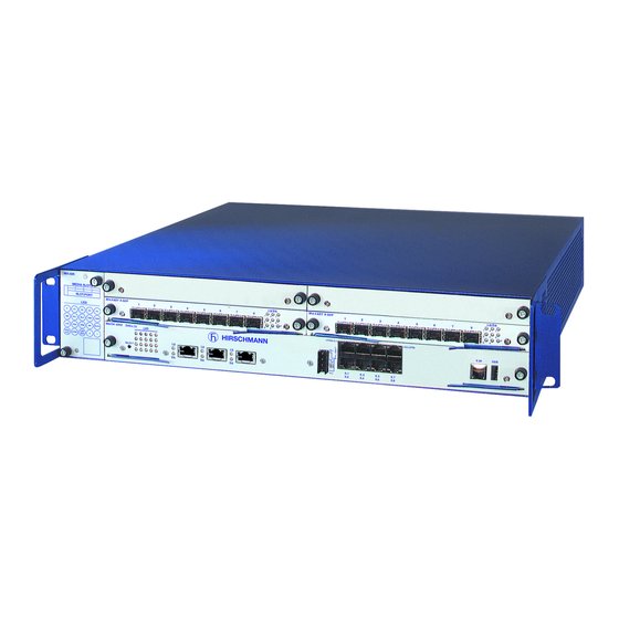
Device description The modular, industry-compatible MACH 4000 Gigabit ETHERNET system is used as an industrial backbone system, and also in applications with high data volumes, such as Voice/Video over IP. The MACH 4000 is a modular, industry-compatible Gigabit ETHERNET sys- tem in a 19"... -
Page 14: Mach 4000 Basic Device
VLAN Topology Discovery Web-based Interface Command Line Interface CLI SNMP 802.1x port authentication Real Time Clock Routing Access Control List ACL The addition, to the MACH range of backbone switches, of the RS20/RS22/ RS30/RS32/RS40 switches of the Open Rail range and the MACH range, the BAT wireless transmission system, the EAGLE security system, and prod- ucts for the LION control room, provides continuous communication across all levels of the company. - Page 15 Figure 2: Ports and media module slots on the MACH 4002-24... MACH 4000 Release 11/08...
- Page 16 Figure 3: Ports and media module slots on the MACH 4002-48... MACH 4000 Release 11/08...
- Page 17 Figure 4: MACH 4000, number of ports and media modules MACH 4000 Release 11/08...
- Page 18 The devices comply with the specifications of the standards: ISO/IEC 8802-3u 100BASE-TX/-1000BASE-TX ISO/IEC 8802-3 100BASE-FX ISO/IEC 8802-3 1000BASE-SX/LX ISO/IEC 8802-3 10GBASE-SR/LR The MACH 4000 basic devices are 2 height modules high (approx. 88mm) and, depending on the device variant and the media modules that are con- nected, they provide you with up to 48 Fast ETHERNET ports up to 48 Gigabit ETHERNET ports...
-
Page 19: Power Supply
Along with the 10-Gigabit (if present), Gigabit and Fast ETHERNET ports, the front of the basic board also has the following connections: A USB socket for connecting an ACA21-USB AutoConfiguration Adapter A V.24 socket for the network management connection Two signal contacts that are integrated together on one socket The LED display block on the left side of the basic board informs you about the status of the device. -
Page 20: Power Supply On Back Of Device
Slot for slide-in power supply unit (voltage input no. 1 and, if required, no. 2) M4-POWER connection (voltage input no. 3, external) M4-POWER connection (voltage input no. 4, external) Figure 5: Back of the MACH 4000 basic device 1.2.1 Power supply on back of device Plug-in power units for MACH 4000 switch chassis M4-S-AC/DC 300W M4-S-24VDC 300W, 2 inputs for redundant power supply... -
Page 21: Fan
Power unit 1 Power unit 2 Power unit 3 M4-POWER power unit chassis, front side of the device (mounting with up to 3 power units) M4-POWER power unit chassis, back side of the device Figure 6: M4-POWER power unit chassis Plug-in power units for M4-POWER power unit chassis M4-P-AC/DC 300W M4-P-24VDC 300W, 2 inputs for redundant power supply... -
Page 22: Monitoring Temperature And Fan
Note: Devices with the M4-AIR-L plug-in fan are suitable for use in an ambi- ent temperature up to a maximum of +40 °C. M4-AIR M4-AIR-L MEDIA SLOTS MEDIA SLOTS SLOT.PORT SLOT.PORT FDX 1000 AN TP/FO FDX 1000 AN TP/FO RING RING PORT STBY TEST PoE... -
Page 23: Integrated Basic Board
MACH 4000 device Ambient - PCB Ambient - PCB temperature difference at full temperature difference at half speed for all fans speed for all fans MACH4002-48+4G 15 °K 20 °K MACH4002-24G/48G 20 °K 27 °K Table 1: Ambient - PCB temperature difference at full and half fan speed Recommendation for temperature monitoring Use the following table (based on half speed for all fans) to monitor the temperature of your device. -
Page 24: Left Area Of Basic Board
1.4.1 Left area of basic board Four Gigabit ETHERNET ports (combo) in MACH 4002-48+4G There are four Gigabit ETHERNET ports (ports number 5.1 to 5.4) for connecting network segments on the left side of the basic board. The ports are RJ45 sockets, each with two integrated LEDs and an SFP slot. If an SFP plug-in module is mounted, the RJ45 socket is switched off. -
Page 25: Right Area Of Basic Board
The following XFP plug-in modules (10-Gigabit ETHERNET SFP trans- ceivers) are available to you for the MACH 4002-...-3X: M-XFP-SR/LC M-XFP-LR/LC M-XFP-ER/LC M-XFP-ZR/LC Order numbers for XFP plug-in modules: (see on page 52 "Order num- bers/product description"). 1.4.2 Right area of basic board 16 Fast ETHERNET ports in MACH 4002-48+4G There are 16 * 10/100BASE-TX ports (ports number 6.1 to 6.16) for con- necting network segments on the right side of the basic board. -
Page 26: Media Modules
8 Gigabit ETHERNET ports in MACH 4002-24G and MACH 4002-24G+3X There are 8 * 10/100/1000BASE-TX ports (ports number 6.1 to 6.8) for connecting network segments on the right side of the basic board. These ports are RJ-45 connections. In the MACH 4002-24G, the RJ45 ports 6.1 to 6.8 can be used as alter- natives to the SFP ports 6.1 to 6.8 on the left side of the basic board (com- bo ports). -
Page 27: M4-8Tp-Rj45
1. Note the PoE capacity limits (see table on page 17). 1.5.1 M4-8TP-RJ45 The M4-8TP-RJ45 media module provides you with eight 10/100BASE-TX ports (RJ-45 connections) for connecting network segments. DA LS DA LS DA LS DA LS DA LS M4-8TP-RJ45 1.5.2 M4-FAST 8TP-RJ45-PoE The M4-FAST 8TP-RJ45 PoE media module provides you with eight 10/... -
Page 28: M4-Giga 8-Sfp
1.5.4 M4-GIGA 8-SFP The M4-GIGA 8-SFP media module has eight 100/1000BASE-FX ports (SFP slots for mounting SFP modules). LS/DA M4-GIGA 8SFP The following SFP plug-in modules are available for the M4-GIGA 8-SFP media module: Gigabit ETHERNET SFP transceiver: Gigabit ETHERNET SFP transceiver: –... -
Page 29: Assembly And Start-Up
Assembly and start-up The devices have been developed for practical application in a harsh indus- trial environment. The installation process is correspondingly simple. On delivery, the device is ready for operation. The following procedure has been proven to be successful for the assembly of the device: Unpacking and checking Installing the media modules... -
Page 30: Installing The Sfp/Xfp Modules
Step 1 Step 2 Step 3 Note the ESD guidelines on page 9 and the safety instructions on page Close the whole of the front surface beside the media modules with cover panels. This provides optimal shielding and convection. The slots for the media modules are all the same. -
Page 31: Installing The Power Supply Unit On The Back Of The Device
Before attaching an SFP or XFP module, first remove the protective cap of the SFP/XFP module. Push the SFP/XFP module with the lock closed into the socket until it latches audibly in place. Note: Only use Hirschmann SFP/XFP modules (see on page 53 "Accesso- ries"). -
Page 32: Setting Up/Mounting The Basic Switch Device In The 19" Rack
Remove the mains voltage supply line. Loosen the four screws used to fasten the plug-in power unit in the basic device and pull the unit out of the basic device, or remove the cover plate of the power unit slot. Slide the new plug-in power unit all the way into the basic device along the mounting rails above and below. - Page 33 For more information on sliding/mounting rails and how to install them, please contact your switch cabinet manufacturer. Install the sliding/mounting rails in the 19" switch cabinet as instructed by the manufacturer, and make sure the device is resting on both rails. Chassis runner LS/D A 6.1...
-
Page 34: Grounding The Device
2.1.7 Grounding the device The device is grounded via the power supply connections. Note: The shielding ground of the connectable twisted pairs lines is connect- ed to the front panel as a conductor. When the device is being operated via the 230/120 VAC power supply unit, it is grounded via the safety plug. -
Page 35: Connecting The Terminal Block For Signal Contact
M4-S-AC/DC 300W MACH 4000 back side of the device MACH 4000 M4-S-AC/DC 300W back side of the device M4-POWER power unit chassis M4-POWER back side of the device Step 1: Connecting the MACH 4000 device(s) to the M4-POWER M4-POWER Power unit 1 Power unit 2 Not mounted power unit chassis... -
Page 36: 10Connecting The Supply Voltage, Starting Up
The defective link status of at least one port. The report of the link status can be masked by the Management for each port. In the delivery state, link status monitoring is deactivated. Failure of the redundancy. An error during the self-test. The following conditions are reported in standby mode: Control cable interrupted Control cable short-circuited... -
Page 37: 11Installing The Data Lines
Note: With non-redundant supply of the mains voltage, the device reports a power failure. You can prevent this message by applying the supply voltage via both inputs, or by changing the configuration in the Management. Note: The 0V connections within a DC module (M4-...-...VDC 300W) are connected with each other. - Page 38 10/100 Mbit/s twisted pair connection PoE 10/100 Mbit/s ports (RJ45 socket) enable the connection of terminal de- vices or independent network segments according to the IEEE 802.3 100BASE-TX / 10BASE-T and IEEE 802.3af (Power over ETHERNET on data lines) standards. These ports support: Autonegotiation Autopolarity Autocrossing (if autonegotiation is activated)
- Page 39 BI_DC- Pin 8 BI_DC+ Pin 7 BI_DA- Pin 6 BI_DD- Pin 5 BI_DD+ Pin 4 BI_DA+ Pin 3 BI_DB- Pin 2 BI_DB+ Pin 1 Figure 14: Pin assignment of the 1000 Mbit/s twisted pair interface 100 Mbit/s F/O connection 100 MBit/s F/O ports (SFP slot) enable the connection of terminal devices or independent network segments in compliance with the IEEE 802.3 100BASE-FX standard.
-
Page 40: 12Replacing The M4-Air
2.1.12 Replacing the M4-AIR... plug-in fan unit The plug-in fan unit (M4-AIR or M4-AIR-L) is replaceable. It may be replaced by an electrician without turning off the device. Depending on the ambient temperature, the device can be operated for a maximum of one to two min- utes with the fan unit removed. - Page 41 M4-8TP-RJ45 Device state MACH 4002 48+4G FDX 1000 TP/FO Port display state RING PORT STBY TEST PoE SELECT Device state These LEDs provide information about conditions which affect the opera- tion of the whole device. P - Power (green LED) Glowing green Internal supply voltage present.
-
Page 42: Port Status Display
RL1 - Relay 1, signal contact (red/yellow LED) Glowing red Signal contact 1 is open, i.e. it is reporting an error. Glowing yellow Signal contact 1 is open, the “Manual Setting” is active Not glowing Signal contact 1 is closed, i.e. it is not reporting an error, or it was closed via the “Manual Setting”. - Page 43 AN - autonegotiation (green LED) Glowing green The port LEDs of the media modules display the port configu- ration type. RING PORT - Ring port (green LED) Glowing green The port LEDs of the media modules display the HIPER-Ring assignment. STBY - stand-by (green LED) Glowing green The port LEDs of the media modules display the assignment...
-
Page 44: Port Status
Port status LS/DA M4-FAST 8SFP DA LS DA LS DA LS DA LS DA LS M4-FAST 8TP-RJ45-PoE LS/DA 6.1 6.16 LS/DA V.24 6.11 6.13 6.15 6.10 6.12 6.14 6.16 These LEDs display port-related information. For each port, the following are available: Two one-color LEDs One two-color LED You set the content of the information with the button on the basic device... -
Page 45: Making Basic Settings
1 to n – TP/FO twisted pair / fi- ber optic (green/yellow LED) Glowing green Twisted pair has been selected. The port LEDs of the media modules display the twisted pair ports. Not glowing Autoselect, no medium has been selected 1 to n –... -
Page 46: Usb Interface
Optical 10 Gbit/s ports: 10 Gbit/s, full duplex All other ports: autonegotiation Redundancy manager disabled Stand-by coupling: disabled USB interface The USB socket has an interface for the local connection of an AutoCon- figuration Adapter ACA 21-USB. It is used for saving/loading the configu- ration and for loading the software. -
Page 47: Disassembly
You will find a detailed description of the configuration in the “Basic Con- figuration User Manual” on the CD-ROM. Disassembly Deinstalling the media modules Step 1 Step 2 Step 3 Note the ESD guidelines on page 9 and the safety instructions on page Lever the selected media module from the slot by pulling the blue in- sertion catches (see Fig. -
Page 48: Technical Data
Technical data General technical data Dimensions MACH 4002-... W x H x D: 480 mm x 88 mm x 435 mm M4-POWER W x H x D: 480 mm x 88 mm x 435 mm Assembly MACH 4002-... 19" switch cabinet M4-POWER 19"... -
Page 49: Interfaces
2. The 0V connections within a DC module (M4-...-...VDC 300W) are connected with each oth- Interfaces Interface Design MACH 4002-... Signal Contact 4-pin pluggable terminal block V.24 access 1 x RJ11 socket USB interface For connecting an AutoConfiguration Adapter ACA 21-USB EMC and immunity EMC interference immunity... - Page 50 Product Wave- Fiber System at- Example Fiber data code length tenuation for LWL M-FAST- line length SFP-... -MM/LC... MM 1310 nm 50/125 µm 0-11 dB 0-5 km 1.0 dB/km, 800 MHz*km -MM/LC... MM 1310 nm 62.5/125 µm 0-8 dB 0-4 km 1.0 dB/km, 500 MHz*km -SM/LC...
-
Page 51: Power Consumption/Power Output
Power consumption/power output Name Power consump- Power output tion MACH 4002-... (without media mod- 110.0 W 376 Btu (IT)/h ules) M4-S-AC/DC 300W (230 V) 350.0 W 1,195 Btu (IT)/h M4-S-AC/DC 300W (110 V) 370.0 W 1,263 Btu (IT)/h M4-S-24VDC 300W 380.0 W 1,297 Btu (IT)/h M4-S-48VDC 300W... -
Page 52: Order Numbers/Product Description
Order numbers/product description Product description Description Order No. Basic devices Basic switch device 48+4G (up to 48 Fast ETHER- NET and 4 Gigabit ETHERNET ports) incl. plug-in fan without power supply MACH4002-48+4G-L2P - with Layer2 Professional software 943 859-101 MACH4002-48+4G-L3E - with Layer3 Enhanced software 943 859-201 MACH4002-48+4G-L3P... -
Page 53: Accessories
Product description Description Order No. M4-P-48VDC 300W Plug-in 48VDC power unit, single-current, for power 943 877-001 unit chassis (2 connections coupled via diodes, one DC/DC converter) Media modules M4-8TP-RJ45 Plug-in module 8 TP RJ45 (10/100, 10/100/1000) 943 863-001 M4-FAST 8TP-RJ45-PoE Plug-in module 8 TP RJ45 PoE (Power over ETH- 943 873-001 ERNET in compliance with IEEE 802.3af, 10/100) M4-FAST 8-SFP... -
Page 54: Underlying Norms And Standards
Name Operating temperature Order number (chassis) M-SFP-LH+/LC 0 °C to +60 °C 943 049-001 Fast ETHERNET SFP Transceiver M-FAST SFP-MM/LC 0 °C to +60 °C 943 865-001 M-FAST SFP-MM / LC EEC -40 °C to +85 °C 943 945-001 M-FAST SFP-SM/LC 0 °C to +60 °C 943 866-001 M-FAST SFP-SM / LC EEC... -
Page 55: Further Support
Further support Further support Technical questions and training courses In the event of technical queries, please talk to the Hirschmann contract partner responsible for looking after your account or directly to the Hirschmann office. You can find the addresses of our contract partners on the Internet: www.hirschmann-ac.com.
Need help?
Do you have a question about the HIRSCHMANN MACH 4000 Series and is the answer not in the manual?
Questions and answers