Table of Contents
Advertisement
Quick Links
User Manual
Installation
MAMMUTHUS Access Layer & Distribution Layer Switch
MTS2600/2700/2800 Family
MAMMUTHUS Power Module – MTM2800-PSU120
MTM2700-PSU500/PSU120/PSU880
MAMMUTHUS Media Module – MTM2700-2X/MTM2800-2X
MTS2624-4X-B
MTS2648-6X-B
MTS2724-4X-FP-S
MTS2724-6X-MP-E
MTS2748-6X-MP-E
MTS2848TF-4X-E
Installation MTS2600/2700/2800
Technical support
Release 02 06/2023
https://hirschmann-it-support.belden.com
Advertisement
Table of Contents

Related Manuals for Belden MAMMUTHUS MTM2800-PSU120


Summary of Contents for Belden MAMMUTHUS MTM2800-PSU120
- Page 1 User Manual Installation MAMMUTHUS Access Layer & Distribution Layer Switch MTS2600/2700/2800 Family MAMMUTHUS Power Module – MTM2800-PSU120 MTM2700-PSU500/PSU120/PSU880 MAMMUTHUS Media Module – MTM2700-2X/MTM2800-2X MTS2624-4X-B MTS2648-6X-B MTS2724-4X-FP-S MTS2724-6X-MP-E MTS2748-6X-MP-E MTS2848TF-4X-E Installation MTS2600/2700/2800 Technical support Release 02 06/2023 https://hirschmann-it-support.belden.com...
- Page 2 The performance characteristics described herein shall be binding only upon the express consent of the parties at the time of signing the contract. This paper is produced by Belden within its capacity. Belden reserves the right to change the contents of this manual without prior notice.
-
Page 3: Table Of Contents
Contents Important Information Safety instructions About this manual Description 1.1 General device description 1.2 Device name and product code 1.2.1 Basic device 1.2.2 Power module 1.2.3 Media module 1.3 Device views 1.3.1 MTS2624-4X-B 1.3.2 MTS2648-6X-B 1.3.3 MTS2724-4X-FP-S 1.3.4 MTS2724-6X-MP-E 1.3.5 MTS2748-6X-MP-E 1.3.6 MTS2824-4X-S 1.3.7 MTS2824-6X-E 1.3.8 MTS2824F-4X-S... - Page 4 1.6.2 Port status 1.7 Management interfaces 1.7.1 DC0 interface (external management) 1.7.2 USB interface 1 Installation 2.1 Checking the package contents 2.2 Installing the power module (optional) 2.3 Installing and grounding the device 2.3.1 Installing the device in a switch cabinet 2.3.2 Installing the device on a vertical flat surface 2.3.3 Grounding the device 2.4 Installing the SFP transceiver (optional)
- Page 5 7.6 Power consumption/power output 7 Scope of delivery, order number, and accessories 8 Underlying technical standards Further support Installation MTS2600/2700/2800 Release 02 06/2023...
-
Page 6: Important Information
Important Information Note: Read these instructions carefully, and familiarize yourself with the device before trying to install, operate, or maintain it. The following notes may appear throughout this documentation or on the device. These notes warn of potential hazards or call attention to information that clarifies or simplifies a procedure. - Page 7 NOTICE NOTICE provides information about procedures that do not involve the risk of injury. Installation MTS2600/2700/2800 Release 02 06/2023...
-
Page 8: Safety Instructions
Safety instructions WARNING UNCONTROLLED MACHINE ACTIONS To avoid uncontrolled machine actions caused by data loss, configure all the data transmission devices individually. Before you start any machine which is controlled via data transmission, be sure to complete the configuration of all data transmission devices. Failure to follow this instruction can result in death, serious injury, or device damage. - Page 9 Verify serial number of delivered products to make sure it is unified with a hardcopy serial number list provided by manufacturer. If it is necessary, please contact Belden representative to obtain a softcopy serial number list from manufacturer for double check.
- Page 10 Requirements for connecting the supply voltage The following requirements apply without restrictions: All variants All of the following requirements are complied with: The supply voltage corresponds to the voltage specified on the type of plate of the device. ...
- Page 11 damaged or their service life shortened by electric field or charge balance effects. You may find information about electrostatic hazard components in DIN EN 61340-5-1 (2007-08) and DIN EN 61340-5-2 (2007-08). Device casing Only technicians authorized by the manufacturer are allowed to open the enclosure.
- Page 12 Germany You find the EU conformity declaration as PDF file for downloading on the Internet at: https://catalog.belden.com Warning! This is a class A device. This device can cause interference in living areas, and in this case the operator may be required to take appropriate measures.
- Page 13 Supplier's Declaration of Conformity 47 CFR § 2.1077 Compliance Information MTS2600/2700/2800 U.S. Contact Information Belden – St. Louis 1 N. Brentwood Blvd. 15th Floor St. Louis, Missouri 63105, United States Phone: 314.854.8000 This device complies with part 15 of the FCC rules.
-
Page 14: About This Manual
Documentation mentioned in the “User Manual Installation” that is not supplied with your device as a printout can be found as PDF files for downloading on the Internet at: https://catalog.belden.com Installation MTS2600/2700/2800 Release 02 06/2023... -
Page 15: Key
The symbols used in this manual have the following meanings: Installation MTS2600/2700/2800 Release 02 06/2023... -
Page 16: Description
Description General device description MTS2600 switch provides an economic choice for port expansion and LAN extension, which enables customers to choose products with good performance, function and flexibility under the condition of tight budget. Users can extend the Gigabit line speed switching performance from the core to access equipment. - Page 17 MTS2724-4X-FP-S MTS2724-6X-MP-E MTS2748-6X-MP-E MTS2824-4X-S MTS2824-6X-E Installation MTS2600/2700/2800 Release 02 06/2023...
- Page 18 MTS2824F-4X-S MTS2848-6X-E MTS2832TF-4X-E MTS2848-6X-S MTS2848TF-4X-E Installation MTS2600/2700/2800 Release 02 06/2023...
- Page 19 Power module MTM2700-PSU120 MTM2700-PSU500 MTM2700-PSU880 MTM2800-PSU120 Installation MTS2600/2700/2800 Release 02 06/2023...
- Page 20 Note:MTM2700-PSU120, MTM2700-PSU500 and MTM2700-PSU880 can only be used in MTS2724-6X-MP-E and MTS2748-6X-MP-E. MTM2800-PSU120 can only be used in MTS2848TF-4X-E. You may choose 1 or 2 power modules with the same input voltage: LV / Ethernet power supply (+) Power modules are provided as accessories. ”Order number”...
- Page 21 Media module MTM2700-2X MTM2800-2X Note:MTM2700-2X can only be used in MTS2724-6X-MP-E and MTS2748-6X-MP-E. MTM2800-2X can only be used in MTS2848TF-4X-E. You can select 1 media module. Media modules are provided as accessories. “Order number” on page 84 Installation MTS2600/2700/2800 Release 02 06/2023...
-
Page 22: Device Name And Product Code
Device name and product code The equipment name corresponds to the product code. 1.2.1 Basic device Order number Product code Description 942999847 MTS2624-4X-B 24 × FE/GE TX, 4 × 1/10 Gbit/s SFP+ slot, single fixed power supply, basic software. 942999839 MTS2648-6X-B 48 ×... -
Page 23: Power Module
1.2.2 Power module Order number Product code Description 942999834 MTM2700-PSU120 AC/DC 120 W power module; AC input 100 V AC … 240 V AC, 2 A; output 12 V DC,10 A; No PoE support. 942999833 MTM2700-PSU500 AC/DC 500 W power module; AC input 100 V AC …... -
Page 24: Device Views
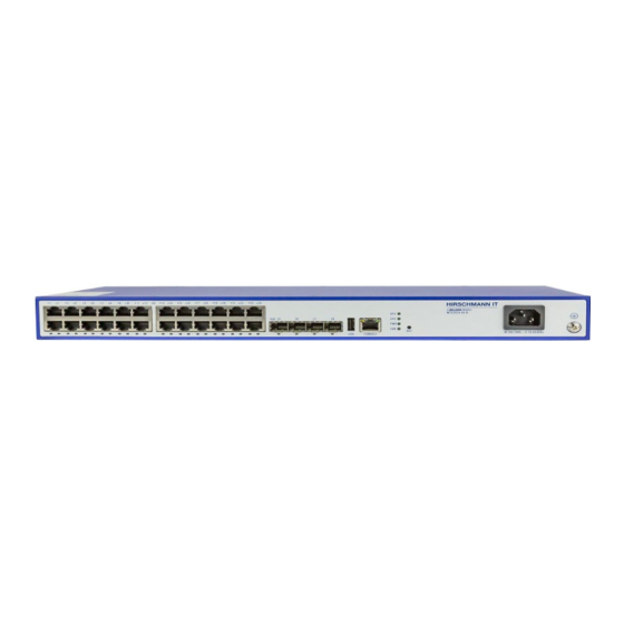
Device views 1.3.1 MTS2624-4X-B Figure 1: Front view Gigabit electrical Interface status LED Gigabit electrical Interface 10 Gigabit optical Interface USB Interface Console port Device status LED Reset button (press and hold for 5 seconds to restart the machine) AC power socket Grounding screw Installation MTS2600/2700/2800 Release 02 06/2023... -
Page 25: Mts2648-6X-B
1.3.2 MTS2648-6X-B Figure 2: Front view Gigabit electrical Interface status LED Gigabit electrical Interface 10 Gigabit optical Interface Console port USB Interface Device status LED Figure 3: Rear view AC power socket Grounding screw Installation MTS2600/2700/2800 Release 02 06/2023... -
Page 26: Mts2724-4X-Fp-S
1.3.3 MTS2724-4X-FP-S Figure 4: Front view Gigabit electrical Interface Status LED Gigabit electrical Interface (with PoE function) 10 Gigabit optical Interface USB Interface Console port Device status LED Reset button (press and hold for 5 seconds to restart the machine) Figure 5: Rear view AC power socket AC power socket... -
Page 27: Mts2724-6X-Mp-E
1.3.4 MTS2724-6X-MP-E Figure 6: Front view Gigabit electrical Interface status LED Gigabit electrical Interface (with PoE function) 10 Gigabit optical Interface USB Interface Console port Device status LED Figure 7: Rear view Interface card slot Modular power supply 1 Modular power supply 2 Grounding screw Installation MTS2600/2700/2800 Release 02 06/2023... -
Page 28: Mts2748-6X-Mp-E
1.3.5 MTS2748-6X-MP-E Figure 8: Front View Gigabit electrical Interface status LED Gigabit electrical Interface (with PoE function) 10 Gigabit optical Interface USB Interface Console port Device status LED Figure 9: Rear view Interface card slot Modular power supply 1 Modular power supply 2 Grounding screw Installation MTS2600/2700/2800 Release 02 06/2023... -
Page 29: Mts2824-4X-S
1.3.6 MTS2824-4X-S Figure 10: Front view Gigabit electrical Interface status LED Gigabit electrical Interface 10 Gigabit optical Interface USB Interface Console port Device status LED Reset button (press and hold for 5 seconds to restart the machine) Figure 11: Rear view AC power socket AC power socket Grounding screw... -
Page 30: Mts2824-6X-E
1.3.7 MTS2824-6X-E Figure 4: Front view USB Interface Console port Gigabit electrical Interface status LED Gigabit electrical Interface Air Inlet of the device 10 Gigabit optical Interface status LED 10 Gigabit optical Interface Device status LED Figure 53: Rear view Air outlet of the device AC power socket Grounding screw... -
Page 31: Mts2824F-4X-S
1.3.8 MTS2824F-4X-S Figure 64: Front view Air Inlet of the device Gigabit optical Interface status LED Gigabit optical Interface 10 Gigabit optical Interface USB Interface Console port Device status LED Reset button (press and hold for 5 seconds to restart the machine) Figure 75: Rear view AC power socket AC power socket... -
Page 32: Mts2832Tf-4X-E
1.3.9 MTS2832TF-4X-E Figure 86: Front view Gigabit optical Interface status LED Gigabit optical Interface Gigabit electrical Interface status LED Gigabit electrical Interface 10 Gigabit optical Interface status LED 10 Gigabit optical Interface Console port USB Interface Device status LED Figure 97: Rear view AC power socket AC power socket Grounding screw... -
Page 33: 1.3.10 Mts2848-6X-E
1.3.10 MTS2848-6X-E Figure 108: Front view USB Interface Console port Gigabit electrical Interface status LED Gigabit electrical Interface Air Inlet of the device 10 Gigabit optical Interface status LED 10 Gigabit optical Interface Device status LED Figure 119: Rear view Air outlet of the device AC power socket Grounding screw... -
Page 34: 1.3.11 Mts2848-6X-S
1.3.11 MTS2848-6X-S Figure 20: Front view USB Interface Console port Gigabit electrical Interface status LED Gigabit electrical Interface Air Inlet of the device 10 Gigabit optical Interface status LED 10 Gigabit optical Interface Device status LED Figure 21: Rear view Air outlet of the device AC power socket Grounding screw... -
Page 35: Mts2848Tf-4X-E
1.3.12 MTS2848TF-4X-E Figure 12: Front view Gigabit electrical Interface status LED Gigabit electrical Interface Gigabit optical Interface status LED Gigabit optical Interface 10 Gigabit optical Interface Console port USB Interface Device status LED Figure 13: Rear view Interface card Slot Modular power supply 1 Modular power supply 2 Grounding screw... -
Page 36: 1.3.13 Power Module
1.3.13 Power module Figure 24: Front view Input status LED Output status LED Handle Air outlet of the device Power switch AC power socket Installation MTS2600/2700/2800 Release 02 06/2023... -
Page 37: 1.3.14 Media Module
1.3.14 Media module Figure 25: Front view 1 Anti-loosening screw 2 Device status LED 3 Gigabit ethernet port 4 Air-outlet of the device Installation MTS2600/2700/2800 Release 02 06/2023... -
Page 38: Power Supply
Power supply You may use the power module to supply voltage to the device. For information about connecting supply voltage: “Power module” on page 23 Installation MTS2600/2700/2800 Release 02 06/2023... -
Page 39: Ethernet Ports
Ethernet ports You can use fiber optic (F/O) to connect end devices and other network segments to the device and the media module ports. 1.5.1 1000 Mbit/s F/O port This port is an SFP slot. The port allows you to connect network components according to IEEE 802.3. This port supports: Full duplex ... -
Page 40: Poe(+) Support
The port allows you to manage the device and upload configuration through the following protocols: SNMP Telnet See “Command line interface user manual” for more information. The manual is available for download on the Internet: https://catalog.belden.com Installation MTS2600/2700/2800 Release 02 06/2023... -
Page 41: Display Elements
Display elements After the supply voltage is set up, the software starts and initializes the device. Afterwards, the device performs a self-test. During this process, various LEDs light up. 1.6.1 Device status These LEDs provide information about the conditions which affect the operation of the whole device. -
Page 42: Port Status
1.6.2 Port status These LEDs provide port information. Indicator Indicator Indicator Status type name color RJ45 Flashing: indicating data sending on serial port self-contained OFF: indicating no data sending on serial port. Serial port yellow LED indicator RJ45 Build-in Flashing: indicating data receiving on serial port green LED OFF: indicating no data receiving on serial port.. -
Page 43: Management Interfaces
Management interfaces 1.7.1 DC0 interface (external management) The serial interface is provided on RJ45 socket (DC0 interface), which can realize the local connection of external management station (VT100 terminal or PC with corresponding terminal emulation). This enables you to set up a connection to the Command Line Interface CLI and to the System Monitor. -
Page 44: Installation
Installation These devices are developed for use in commercial environments. At the time of delivery, the equipment is ready for operation. Perform the following work steps to install and configure the device: Checking the package contents Installing the power module (optional) ... -
Page 45: Installing And Grounding The Device
Installing and grounding the device Perform the following work steps: Installing the device in the switch cabinet Installing the device on a vertical flat surface Grounding the device 2.3.1 Installing the device in a switch cabinet WARNING ELECTRIC SHOCK Install this device solely in a switch cabinet or in an operating site with restricted access, to which maintenance staff have exclusive access. - Page 46 Note: When the device is operated in an environment with continuous vibration load greater than 0.7 g, it must be fixed to the switch cabinet with the 2 fixed mounting brackets at the front and rear of the device. Additional mounting brackets are provided as accessories. “Accessories”...
- Page 47 Figure 28: Installing the device in a switch cabinet Installation MTS2600/2700/2800 Release 02 06/2023...
-
Page 48: Installing The Device On A Vertical Flat Surface
2.3.2 Installing the device on a vertical flat surface WARNING FIRE RISK In case of vertical installation, install the device in a fireproof enclosure. Failure to follow this instruction can result in death, serious injury, or device damage. Perform the following work steps: ... -
Page 49: Grounding The Device
2.3.3 Grounding the device WARNING ELECTRIC SHOCK Ground the device before connecting any other cables. Failure to follow this instruction can result in death, serious injury, or device damage. The device has the connection of the protective grounding wire. The device is grounded by the grounding screw and the power socket. Perform the following work steps: ... -
Page 50: Installing The Sfp Transceiver (Optional)
Installing the SFP transceiver (optional) Prerequisite: Exclusively use Hirschmann IT SFP transceivers. “Accessories” on the page Perform the following work steps: Take the SFP transceiver out of the transport packaging. Remove the protection cap from the SFP transceiver. See Figure ... -
Page 51: Operating The Device
Operating the device Perform the following work step: Connect the power supply cable, see Figure Enable the power supply. Figure 17: Connect the power supply Connecting data cables Note the following general recommendations for data cable connections in an environment with high electrical interference levels: ... -
Page 52: Filling Out The Inscription Label
Filling out the inscription label The information field for the MAC address helps you identify your device. Installation MTS2600/2700/2800 Release 02 06/2023... -
Page 53: Making Basic Settings
Making basic settings Note: Configuring 2 or more devices with the same IP address may lead to the network’s failure to function as expected. Install and maintain a program, to assign a unique IP address to each device in the network. Enter the IP parameters when you install the device for the first time. -
Page 54: Monitoring The Ambient Air Temperature
Monitoring the ambient air temperature Operate the device below the specified maximum ambient air temperature exclusively. ”General technical data” on page 59 The ambient air temperature is the temperature of the air at a distance of 5 cm (2 in) from the device. It depends on the installation conditions of the device, for example, the distance from other devices or other objects, and the output of neighboring devices. -
Page 55: Maintenance And Service
You find information and software downloads on the Hirschmann IT product pages on the Internet https://catalog.belden.com. Depending on the degree of pollution in the operating environment, check at regular intervals that the ventilation slots in the device are not obstructed. -
Page 56: Disassembly
Disassembly Removing the power module (optional) Perform the following work steps: Pull the power module out of the power module slot. Blank the power module slot on the device using the cover plate. Removing the media module Perform the following work steps: ... -
Page 57: Removing The Sfp Transceiver (Optional)
Removing the SFP transceiver (optional) Perform the following work steps: Release the lock and pull the SFP transceiver out of the device slot. Figure Figure 18: Releasing the lock Use a protective cover to blank the SFP transceiver. Figure Figure 36: Installing the Protective Cover Installation MTS2600/2700/2800... -
Page 58: Removing The Device
Removing the device WARNING ELECTRIC SHOCK Please disconnect all other cables before disconnecting the ground wire. Failure to follow these instructions can result in death, serious injury, or device damage. Perform the following work steps: Disconnect the data cables. ... -
Page 59: Technical Data
Technical data General technical data Basic device Dimensions “Dimension drawings” on page 61 W × H × D Weight MTS2624-4X-B 2.8 kg (6.17 lb) MTS2648-6X-B 6 kg (13.22 lb) MTS2724-4X-FP-S 5.5 kg (12.12 lb) MTS2724-6X-MP-E 6 kg (13.22 lb) MTS2748-6X-MP-E 6 kg (13.22 lb) MTS2832TF-4X-E... - Page 60 Power module Size “Dimension drawings” on page 73 Weight MTM2700-PSU120 0.9 kg (1.98 lb) MTM2700-PSU500 1.2 kg (2.64 lb) MTM2700-PSU880 1.4 kg (3.09 lb) MTM2800-PSU120 0.9 kg (1.98 lb) Installation of the Tightening torque 0.4 Nm … 0.6 Nm (3.5 lb-in … 5.2 lb-in) power module Installation of the Tightening torque...
-
Page 61: Dimension Drawings
Dimension drawings Basic device MTS2624-4X-B Installation MTS2600/2700/2800 Release 02 06/2023... - Page 62 MTS2648-6X-B Installation MTS2600/2700/2800 Release 02 06/2023...
- Page 63 MTS2724-4X-FP-S Installation MTS2600/2700/2800 Release 02 06/2023...
- Page 64 MTS2724-6X-MP-E Installation MTS2600/2700/2800 Release 02 06/2023...
- Page 65 MTS2748-6X-MP-E Installation MTS2600/2700/2800 Release 02 06/2023...
- Page 66 MTS2832TF-4X-E Installation MTS2600/2700/2800 Release 02 06/2023...
- Page 67 MTS2824F-4X-S Installation MTS2600/2700/2800 Release 02 06/2023...
- Page 68 MTS2824-4X-S Installation MTS2600/2700/2800 Release 02 06/2023...
- Page 69 MTS2848-6X-S Installation MTS2600/2700/2800 Release 02 06/2023...
- Page 70 MTS2824-6X-E Installation MTS2600/2700/2800 Release 02 06/2023...
- Page 71 MTS2848-6X-E Installation MTS2600/2700/2800 Release 02 06/2023...
- Page 72 MTS2848TF-4X-E Installation MTS2600/2700/2800 Release 02 06/2023...
- Page 73 Power module MTM2700-PSU120 Installation MTS2600/2700/2800 Release 02 06/2023...
- Page 74 MTM2700-PSU500 Installation MTS2600/2700/2800 Release 02 06/2023...
- Page 75 MTM2700-PSU880 Installation MTS2600/2700/2800 Release 02 06/2023...
- Page 76 MTM2800-PSU120 Installation MTS2600/2700/2800 Release 02 06/2023...
- Page 77 Media module MTM2700-2X Installation MTS2600/2700/2800 Release 02 06/2023...
- Page 78 MTM2800-2X Installation MTS2600/2700/2800 Release 02 06/2023...
-
Page 79: Electromagnetic Compatibility (Emc)
Electromagnetic compatibility (EMC) EMC interference Standard emission application EN 55032 Class A DNV GL Guide — FCC 47 CFR Part 15 Class A EN 61000-6-4 Fulfilled EN 55032 AC/DC Power Line Class A DNV GL Guide AC/DC Power Line — FCC 47 CFR Part 15 AC/DC Power Line Class A... - Page 80 EMC immunity Standard application Electromagnetic field EN 61000-4-3 80 MHz ... 1000 MHz 10 V/m 1000 MHz ... 6000 MHz 3 V/m IEEE 1613 80 MHz ...1000 MHz — Fast transient (burst) EN 61000-4-4 AC/DC Power Line ±2 kV IEEE C37.90.1 EN 61000-4-4 Data cable ±1 kV...
-
Page 81: Immunity
EMC immunity Standard application Damped vibration - AC/DC Power Line EN 61000-4-12 Cable / ground — IEEE C37.90.1 EN 61000-4-12 Cable / cable — IEEE C37.90.1 Damped oscillation - data cable EN 61000-4-12 Cable / ground — IEEE C37.90.1 EN 61000-4-12 Cable / cable —... -
Page 82: Network Range
Network range Note: The line length specified for the transceiver applies to the corresponding fiber data (fiber attenuation and BLP/dispersion). Product code Wave Optical BLPc/disper MTS-SFP-1G-.. Mode F/O cable length example length attenuation sion Full Duplex -TX/RJ45... TX/RJ45 100 m Negotiation -SX/LC... - Page 83 Power consumption/power output Name Maximum Power output power consumption Basic device MTS2624-4X-B 26 W 91 Btu (IT)/h MTS2648-6X-B 75 W 256 Btu (IT)/h MTS2724-4X-FP-S 29 W 101.5 Btu (IT)/h MTS2724-6X-MP-E 34 W 119 Btu (IT)/h MTS2748-6X-MP-E 46 W 161 Btu (IT)/h MTS2832TF-4X-E 60 W 210 Btu (IT)/h...
- Page 84 Scope of delivery, order number, and accessories Delivery item Quantity Articles Device Safety and general information sheet Bracket Order number MTS2624-4X-B 942 999-847 MTS2648-6X-B 942 999-839 MTS2748-6X-MP-E 942 999-831 MTS2724-6X-MP-E 942 999-832 MTS2700-PU880 942 999-837 MTM2700-PSU500 942 999-833 MTM2700-PSU120 942 999-834 MTS2724-4X-FP-S...
- Page 85 MTS-SFP-1G-BIDI-TypeB-LX/LC 942 999-861 MTS-SFP-1G-LX+/LC-1550 942 999-862 10G SFP module Order number MTS-SFP-10G-SR/LC 942 999-851 MTS-SFP-10G-LR/LC 942 999-852 MTS-SFP-10G-ER/LC 942 999-853 MTS-SFP-10G-TX/RJ45 942 999-867 You may access more information about certificates here: https://catalog.belden.com Installation MTS2600/2700/2800 Release 02 06/2023...
- Page 86 Underlying technical standards Name FCC 47CFR Part 15 Code of Federal Regulations IEC 60825-1 Safety of Laser Products EN 55032 Electromagnetic compatibility of multimedia equipment. Emission Requirements EN 55035 Electromagnetic compatibility of multimedia equipment. Immunity Requirements EN 62368-1 Information technology equipment - Safety - Part 1: General requirements EN 61000-3-2 Electromagnetic compatibility (EMC) - Part 3-2: Threshold -...
- Page 87 Hirschmann IT directly. A list of local telephone numbers and email addresses for technical support directly from Hirschmann IT is available at, https://hirschmann-it-support.belden.com This site also includes a free of charge knowledge base and a software download section. Installation MTS2600/2700/2800...
- Page 88 Installation MTS2600/2700/2800 Release 02 06/2023...
Need help?
Do you have a question about the MAMMUTHUS MTM2800-PSU120 and is the answer not in the manual?
Questions and answers