
Related Manuals for Belden Hirschmann MICE MS20


Summary of Contents for Belden Hirschmann MICE MS20
- Page 1 User Manual Installation Industrial ETHERNET Switch MICE MS20/MS30 MICE MS20 MICE MS30 Installation MS20/MS30 Technical Support Release 13 09/2019 https://hirschmann-support.belden.com...
- Page 2 The naming of copyrighted trademarks in this manual, even when not specially indicated, should not be taken to mean that these names may be considered as free in the sense of the trademark and tradename protection law and hence that they may be freely used by anyone. ©...
-
Page 3: Table Of Contents
Contents Safety instructions About this Manual Legend Description General device description Device name and product code Description of the device variants 1.3.1 Number of ports and connections 1.3.2 Media modules 1.3.3 Digital I/O Module MM24 1.3.4 MB20 extender module 1.3.5 SFP Transceiver Ethernet ports 1.4.1 10/100/1000 Mbit/s twisted pair port 1.4.2 10/100 Mbit/s twisted pair port... - Page 4 Adjusting the DIP switch settings on the MM20-A8A89999SAHH media module Connecting the MM22-T1T1T1T1 PoE media module Terminal block for supply voltage and signal contact 2.9.1 Supply voltage 2.9.2 Signal contacts 2.10 Connecting the terminal blocks, start-up procedure 2.10.1 Terminal blocks on MS20/MS30-...A... and MS20/ MS30-...C...
-
Page 5: Safety Instructions
Safety instructions WARNING UNCONTROLLED MACHINE ACTIONS To avoid uncontrolled machine actions caused by data loss, configure all the data transmission devices individually. Before you start any machine which is controlled via data transmission, be sure to complete the configuration of all data transmission devices. Failure to follow these instructions can result in death, serious injury, or equipment damage. - Page 6 Note: Observe the control drawing (document number 000160011DNR) on the following pages. Relevant for Europe for devices installed in explosive gas atmospheres according to ATEX directive 2014/34/EU: Make sure that the device has the following label: II 3G (... followed by additional specifications). Note: Observe the control drawing (document number 000160011DNR) on the following pages.
- Page 7 Zone 2: Explosive Atmosphere Ordinary Location, or Class I, Division 2, Non-Hazardous Area, Groups A, B, C, D non-explosive atmosphere Hazardous Location WARNING! The USB connection and the V.24 Interface connection are for temporary MS20/30 switch basic module with voltage range type “C” connection only, for maintenance use.
- Page 8 Ordinary Location, Zone 2: Explosive Non-Hazardous Area, Atmosphere non-explosive atmosphere or Class I Division 2 Groups A, B, C, D Hazardous Location WARNING! The USB connection and the V.24 Interface connection are for temporary MS20/30 switch basic module with voltage range type “A” connection only, for maintenance use.
- Page 9 For Use in explosive atmospheres under the European directive 2019/34/EU: Applied Standards: EN 60079-0: 2012 + A11: 2013 EN 60079-15: 2010 EN 60079-11: 2012 The Use in Hazardous Locations with explosive atmospheres is only allowed for MS20 or MS30 model No´s.
- Page 10 For Use in Hazardous Locations Class I Division 2 Groups A, B, C, D: Applied standard: ANSI/ISA 12.12.01-2011. Only allowed for MS20 or MS30 model No´s. which are individually labelled “FOR USE IN HAZARDOUS LOCATIONS” Nonincendive field wiring circuits must be wired in accordance with the National Electrical Code (NEC), NFPA 70, article 501.
- Page 11 IECEx – Certification Scheme for Explosive Atmospheres Relevant for MS20/MS30 series devices installed in explosive gas atmospheres according to IECEx: Observe the “Conditions for safe use for Industrial Ethernet RAIL Switch MS20 and MS30 devices 943-435-999 according to the IECEx Certification Scheme”...
- Page 12 Zone 2: Explosive Atmosphere Ordinary Location, Non-Hazardous Area, non-explosive atmosphere WARNING! The USB connection and the V.24 Interface connection are for temporary MS20/30 switch basic module with voltage range type “C” connection only, for maintenance use. Do not use, connect or disconnect unless the area is known to be non-hazardous.
- Page 13 Ordinary Location, Zone 2: Explosive Atmosphere Non-Hazardous Area, non-explosive atmosphere WARNING! The USB connection and the V.24 Interface connection are for temporary MS20/30 switch basic module with voltage range type “A” connection only, for maintenance use. Do not use, connect or disconnect unless the area is known to be non-hazardous.
- Page 14 For Use in explosive atmospheres under the IECEx Scheme: Applied Standards: IEC 60079-0:2011 + Corr. 1:2012 + Corr. 2:2013 IEC 60079-15:2010 The Use in Hazardous Locations with explosive atmospheres is only allowed for MS20 or MS30 model No´s. which are individually labelled “Ex nA IIC T4 Gc”...
- Page 15 Shielded ground The shielded ground wire of the twisted pairs cables is connected to the front panel as a conductor. Beware of possible short circuits when connecting a cable section with conductive shield braiding. Device casing WARNING ELECTRIC SHOCK Never insert sharp objects (small screwdrivers, wires, etc.) into the inside of the device.
- Page 16 Keep the ventilation slits free to ensure good air circulation. Make sure there is at least 3.94 inches (10 cm) of space in front of the ventilation slits of the housing. The device must be installed in the vertical position (see figure ...
- Page 17 General safety instructions You operate this device with electricity. Improper usage of the device entails the risk of physical injury or significant property damage. Before connecting any cable, read this document, and the safety instructions and warnings. See “Supply voltage” on page 5. General safety instructions ...
- Page 18 In accordance with the above-named EU directive(s), the EU conformity declaration will be available to the relevant authorities at the following address: Hirschmann Automation and Control GmbH Stuttgarter Str. 45-51 72654 Neckartenzlingen Deutschland www.hirschmann.com The product can be used in living areas (living area, place of business, small business) and in industrial areas.
-
Page 19: About This Manual
About this Manual The “Installation” user manual contains a device description, safety instructions, a description of the display, and the other information that you need to install the device. The following manuals are available as PDF files on the CD/DVD supplied: ... -
Page 20: Legend
Legend The symbols used in this manual have the following meanings: Listing Work step Subheading Installation MS20/MS30 Release 13 09/2019... -
Page 21: Description
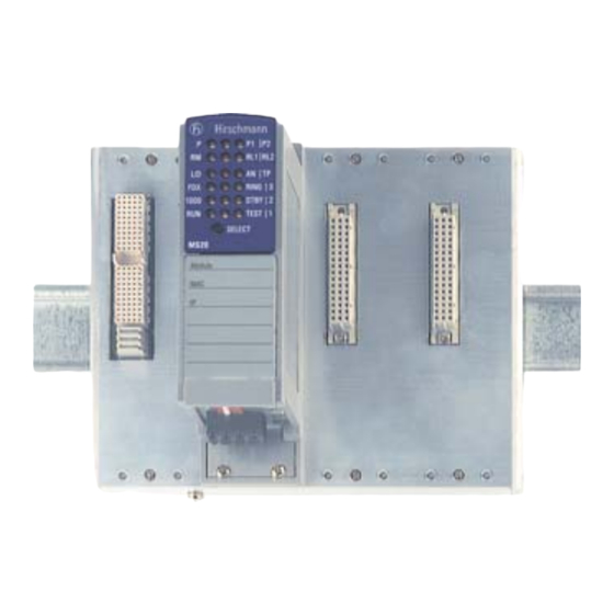
Description General device description MS20 MS30 Figure 1: MICE basic module equipped with media modules 1 - basic module 2 - media module 3 - slot for media module You can choose from between a wide range of variants. You have the option to set up your device individually based on different criteria: ... - Page 22 There are convenient options for managing the device. Administer your devices via: a Web browser Telnet network management software (e.g. Industrial HiVision) a V.24 interface (locally on the device) The devices provide you with a large range of functions, which the manuals for the operating software inform you about.
-
Page 23: Device Name And Product Code
You have numerous options of combining the device characteristics. You can determine the possible combinations using the configurator which is available in the Belden E-Catalog (www.e-catalog.beldensolutions.com) on the web page of the device. Position Characteristic... -
Page 24: Description Of The Device Variants
Description of the device variants The industrial ETHERNET series MICE (Modular Industrial Communication Equipment) consists of a basic switch module and the media modules. These devices can be managed. A basic module contains all the functions of this industrial Switch, with the exception of the interfaces to the LAN that is connected. -
Page 25: Number Of Ports And Connections
1.3.1 Number of ports and connections Device versions with 10/100 Mbit/s ports MS20-0800..., MS20-1600..., MS20-2400... Depending on the variant, the MS20 basic modules provide you with the following number of slots for media modules and the following maximum number of connectable network segments: Basic module Number of slots for Max. - Page 26 Figure 3: Interfaces of the MS20-... and MS30-... on the bottom of the device 1 - Terminal block (power 2) 2 - DIP switch 3 - Terminal block (power 1) 4 - USB port 5 - V.24 port 6 - MICE MS20/30 switch basic module with 18 V DC ... 60 V DC voltage range 7 - Terminal block (power 2) 8 - Terminal block (power 1)
- Page 27 Figure 4: Connections of the MS20-.../MS30-...E on the bottom of the device 1 - Terminal block 6-pin for power and signal contact 2 - DIP switch 3 - USB port 4 - V.24 port 5 - MICE MS20/30-...E... basic module with voltage range 18 V DC ...
- Page 28 Device variants with 1000 Mbit/s and 10/100 Mbit/s ports MS30-0802..., MS30-1602..., MS30-2402... Depending on the variant, the MS30 basic modules provide you with the following number of slots for media modules and the following maximum number of connectable network segments: Basic module Number of Number of Max.
-
Page 29: Media Modules
1.3.2 Media modules The MICE media modules form the interface of the device to the LAN. They can be attached in the Basic module MS20-... Basic module MS30-... They differ with regard to the number of interfaces and the media type. The different interfaces of the media modules provide you with the following interface-specific functions: ... - Page 30 MM2 media modules MM2 media modules TP ports 10/ F/O port F/O port F/O port F/O port Module type 100 Mbit/s multi-mode multi-mode single- single- 10 Mbit/s 100 Mbit/s mode 1300 mode 1550 nm, 100 nm, 100 Mbit/s Mbit/s MM2 - 4TX1 (- EEC) 4, RJ45 –...
- Page 31 MM3 media modules MM3 media modules TP ports 10/ F/O port F/O port F/O port F/O port Module type 100 Mbit/s multi-mode multi-mode single- single- 10 Mbit/s 100 Mbit/s mode 1300 mode 1550 nm, 100 nm, 100 Mbit/s Mbit/s MM3-4TX5 4, M12 –...
- Page 32 MM22-T1T1T1T1 PoE media module The MM22-T1T1T1T1 PoE media module (deeper module design) supports Power over ETHERNET (PoE) according to IEEE 802.3af. It allows the connection and remote supply of IP telephones (Voice over IP), webcams, sensors, printer servers and WLAN access points via 10BASE- T/100BASE-TX, for example.
- Page 33 Figure 8: Port assignment 1 - Port 1 (twisted pair) 2 - Port 2 (twisted pair) 3 - Port 3 (twisted pair) 4 - Port 4 (twisted pair) 1* - Port 1* (SFP slot, can be used as alternative to port 1) 2* - Port 2* (SFP slot, can be used as alternative to port 2) 3* - Port 3* (SFP slot, can be used as alternative to port 3) 4* - Port 4* (SFP slot, can be used as alternative to port 4)
-
Page 34: Digital I/O Module Mm24
1.3.3 Digital I/O Module MM24 The Digital I/O Module MM24 allows the control of different actuators of the system via 4 digital inputs and outputs. For further information, see the user manual MICE digital I/O module MM24. 1.3.4 MB20 extender module The MB20 extender module allows you to add 2 slots for media modules to the MS20-1600/MS30-1602 basic modules. -
Page 35: Ethernet Ports
Ethernet ports You can connect end devices and other segments to the device ports using twisted pair cables or optical fibers (F/O). You find information on pin assigments for making patch cables here: “Pin assignments” on page 37 1.4.1 10/100/1000 Mbit/s twisted pair port The 10/100/1000 Mbit/s twisted pair port offers you the ability to connect network components according to the IEEE 802.3 10BASE-T/100BASE-TX/ 1000BASE-T standard. -
Page 36: 10/100 Mbit/S Twisted Pair Port
1.4.2 10/100 Mbit/s twisted pair port This port is an RJ45 socket. The 10/100 Mbit/s twisted pair port offers you the ability to connect network components according to the IEEE 802.3 10BASE-T/100BASE-TX standard. This port supports: Autonegotiation Autopolarity ... -
Page 37: 100 Mbit/S F/O Port
1.4.5 100 Mbit/s F/O port This port is an MTRJ, ST, or DSC socket. The 100 Mbit/s F/O port offers you the ability to connect network components according to the IEEE 802.3 100BASE-FX standard. This port supports: Full or half duplex mode Default setting: Full duplex 1.4.6 Pin assignments... -
Page 38: Aui Port
M12 8-pin (X-coded) 10/100 Mbit/s 1000 Mbit/s BI_DB+ Negative V RX− BI_DB− Negative V BI_DA+ Positive V TX− BI_DA− Positive V — BI_DC+ — — BI_DC− — — BI_DD− — — BI_DD+ — AUI port The housing of the Sub-D plug is electrically isolated from the lower panel of the device. -
Page 39: Display Elements
9 - Pin 9: Output CI-B 10 - Pin 10: Input DO-B 11 - Pin 11: Shielding DO 12 - Pin 12: Output DI-B 13 - Pin 13: Voltage 12 V 14 - Pin 14: Shielding 12 V 15 - Pin 15: Not contacted Connect the ports of the media modules plugged into the basic module as required in order to set up your industrial Ethernet or expand your existing network. -
Page 40: Device Status
1.6.1 Device status These LEDs provide information about conditions which affect the operation of the whole device. P – Power (green LED) Glowing green Internal supply voltage present. Not glowing Internal supply voltage is too low. P1 – Power 1 (green LED) Glowing green Supply voltage 1 is present. -
Page 41: Display Status
1.6.2 Display status Every media module has one LED per port. The meaning of this port status LED depends on the setting on the basic module. You define the display meaning with the "SELECT" button on the basic module. Press the button for approx. 2 seconds to switch the meaning of the display. -
Page 42: Port Status
1.6.3 Port status These LED's display port-related information. You set the content of the information with the button on the basic module (see on page 41 “Display status”). 1 to 4 – data, link status (green/yellow LED) Not glowing For MM20-A8A89999SAHH (AUI): No valid connection. No DTE voltage at the port. -
Page 43: Installation
Installation The devices have been developed for practical application in a harsh industrial environment. Hirschmann supplies the device ready for operation. Perform the following steps to install and configure the device: Checking the package contents Installing media modules ... -
Page 44: Installing Media Modules
Installing media modules On delivery, the device is ready for operation. You can install and remove media modules during running operation. To attach a media module, first remove the protective cap on the plug. Plug the media module onto the plug. ... - Page 45 Figure 13: Labels for basic modules and media modules 1 - MICE basic module 2 - Lable for the name of the module 3 - Lable for MAC address of the device 4 - Lable for IP address of the device 5 - Lable for other entries on your demand 6 - MICE media module 7 - Lable for the name of the media module...
-
Page 46: Installing An Sfp Transceiver (Optional)
Installing an SFP transceiver (optional) Use only Hirschmann SFP transceivers which are suitable for usage with the device. See “Accessories” on page 77. Proceed as follows: Remove the protection cap from the SFP transceiver. Push the transceiver with the lock closed into the slot until it latches in. Adjusting the DIP switch settings on the basic module (4-pin DIP switch) The 4-pin DIP switch on the bottom panel of the basic module provides you... - Page 47 “Ring-Port” switch MICE device Ring ports for the HIPER-Ring Position MS20 Module 1/Port 1 and Module 1/Port 2 MS20 Module 1/Port 1 and Module 2/Port 1 MS30 Module 1/Port 1 and Module 1/Port 2 MS30 Module 2/Port 1 and Module 2/Port 2 Table 5: Selecting ring ports for the HIPER-Ring Switch...
-
Page 48: Basic Module (3-Pin Dip Switch)
Adjusting the DIP switch settings on the MS20/MS30-...E... basic module (3-pin DIP switch) The 3-pin DIP switch on the bottom panel of the basic module gives you the following options: DIP switch Function State on delivery RM (redundancy When the HIPER-Ring function is OFF position (RM function manager) switched on, you can switch the RM... -
Page 49: Adjusting The Dip Switch Settings On The Mm20-A8A89999Sahh Media Module
OFF ON Figure 15: 3-pin DIP switch on the MICE basic module MS20/MS30-...E... 1 - Switch 1, position ON, Function: Redundancy Manager (RM) 2 - Switch 2, position ON, Function: Mod. 1 Port 1 & Mod. 2 Port 1 3 - Switch 3, position ON, Function: Stand-by 4 - Switch 1, position OFF, Function: - 5 - Switch 2, position OFF, Function: Ring Port: Mod. - Page 50 The twisted-pair cables at ports 1 to 4 are supplied with PoE voltage via the spare pairs (pins 4 & 5 and 7 & 8 of the RJ45 sockets). Note: Only use the Hirschmann RPS60/48V EEC power supply unit to supply the PoE voltage.
-
Page 51: Terminal Block For Supply Voltage And Signal Contact
Terminal block for supply voltage and signal contact The supply voltage and the signal contacts are connected via a 4-pin terminal block and a redundant 4-pin terminal block with a snap lock. 2.9.1 Supply voltage The supply voltage can be connected redundantly. Both inputs are uncoupled. -
Page 52: Connecting The Terminal Blocks, Start-Up Procedure
2.10 Connecting the terminal blocks, start-up procedure Pull the terminal block off the device and connect the voltage supply lines and the signal lines. 2.10.1 Terminal blocks on MS20/MS30-...A... and MS20/ MS30-...C... Products with voltage range A or C (product code position 15—see table have two 4-pin terminal blocks. -
Page 53: Terminal Block On Ms20/Ms30
2.10.2 Terminal block on MS20/MS30-...E... Products with voltage range E (product code position 15 – see table 1 on page 23) have one 6-pin terminal block. +24 V (P1) Relay +24 V (P2) Figure 17: Pin assignment of the 6-pin terminal block 1 - Pin 1 = +24V (P1) 2 - Pin 2 = Relay 3 - Pin 3 = 0 V... -
Page 54: Installing And Grounding The Device
2.11 Installing and grounding the device 2.11.1 Installing the device onto the DIN rail Verify that there is at least 4 in (10 cm) of space above and below the device. The overall shield of a connected shielded twisted pair cable is connected to the ground connector on the front panel as a conductor. -
Page 55: Grounding The Device
2.11.2 Grounding the device The lower panel of the device casing is grounded via the DIN rail and optionally by means of the separate ground screw. See figure 2 on page 25. 2.12 Connecting data cables 2.12.1 Twisted Pair ports In general, adhere to the following recommendations for data cable connections in environments with high electrical interference levels: ... -
Page 56: Assembly Of The Mb20 Extender Module
2.13 Assembly of the MB20 extender module The MB20 extender module allows you to expand the MS20-1600 and MS30-1602 basic module with two sockets for media modules. You can install the MB20 extender module in running operation. On the right side of the basic module, loosen the screws at the top and bottom (1-3 revolutions). -
Page 57: Making Basic Settings
Making basic settings The IP parameters must be entered when the device is installed for the first time. The device provides 6 options for configuring IP addresses: Entry via V.24 connection Entry using the HiDiscovery protocol via the application HiDiscovery or Industrial HiVision ... - Page 58 V.24 interface (external management) A serial interface is provided on the RJ11 socket (V.24 interface) for the local connection of an external management station (VT100 terminal or PC with appropriate terminal emulation) or an AutoConfiguration Adapter ACA11. This enables you to set up a connection to the Command Line Interface (CLI) and to the system monitor.
-
Page 59: Maintenance And Service
Maintenance and service When designing this device, Hirschmann largely avoided using high-wear parts. The parts subject to wear and tear are dimensioned to last longer than the lifetime of the product when it is operated normally. Operate this device according to the specifications. ... -
Page 60: Disassembly
Disassembly Removing the device Proceed as follows: Disconnect the data cables. Disable the supply voltage. Disconnect the terminal blocks. Disconnect the grounding. To remove the device from the DIN rail, press the device downwards and pull it out from under the DIN rail. -
Page 61: Removing An Sfp Transceiver (Optional)
Removing an SFP transceiver (optional) Pull the SFP transceiver out of the slot by means of the opened lock. Close the SFP transceiver with the protective cap. Installation MS20/MS30 Release 13 09/2019... -
Page 62: Technical Data
Technical data General technical data Dimensions MS20-0800... 125 mm × 133 mm × 100 mm (140 mm W × H × D MS30-0802... 163 mm × 133 mm × 100 mm (140 mm MS20-1600... 202 mm × 133 mm × 100 mm (140 mm MS30-1602... - Page 63 Dimension drawings 1.14 5.24 0.16 0.83 0.16 1.14 0.83 5.24 0.16 0.16 1.14 0.83 5.24 0.16 Figure 20: Dimensions of base module MS20 variants and extender module Installation MS20/MS30 Release 13 09/2019...
- Page 64 1.14 0.83 0.16 0.16 5.24 1.14 0.83 5.24 0.16 0.16 1.14 0.83 5.24 0.16 Figure 21: Dimensions of base module MS30 variants and extender module Installation MS20/MS30 Release 13 09/2019...
- Page 65 5.35 inch 2.87 4.53 MM... 24 V MM... 48 V Figure 22: Dimensions of media modules Installation MS20/MS30 Release 13 09/2019...
- Page 66 EMC and immunity EMC interference Standard Marine Railway Sub-station emission applications applications applications applications (trackside) Radiated emission EN 55032 Class A Class A Class A Class A GL Guidelines — EMC 1 — — FCC 47 CFR Part 15 Class A Class A Class A...
- Page 67 EMC interference Standard Marine Railway Sub-station immunity applications applications applications applications (trackside) Electrostatic discharge EN 61000-4-2 Contact discharge ± 4 kV ± 6 kV ± 6 kV ± 8 kV IEEE C37.90.3 EN 61000-4-2 Air discharge ± 8 kV ± 8 kV ±...
- Page 68 EMC interference Standard Marine Railway Sub-station immunity applications applications applications applications (trackside) Damped vibration – DC supply connection EN 61000-4-12 line/ground — — — 2.5 kV IEEE C37.90.1 EN 61000-4-12 line/line — — — 1 kV IEEE C37.90.1 Damped oscillation - data line EN 61000-4-12 line/ground —...
- Page 69 Stability Standard Marine Railway Sub-station applications applications applications applications (trackside) IEC 60068-2-6, test Fc Vibration — 2 Hz ... 13.2 Hz — — with 0.04 in. (1 mm) amplitude — — — 2 Hz ... 9 Hz with 0.12 in. (3 mm) amplitude 5 Hz ...
- Page 70 Network range Note: The line lengths specified for the transceivers apply for the respective fiber data (fiber attenuation and BLP/dispersion). AU port Length of an AUI cable max. 50 m Table 10: AUI port 10/100/1000 Mbit/s twisted pair port Length of a twisted pair segment max.
- Page 71 Product Wave Fiber System Example Fiber BLP/ code length attenua- for F/O line attenua- dispersion M-FAST- tion length tion SFP-... -MM/LC... MM 1310 nm 50/125 µm 0-8 dB 0-5 km 1.0 dB/km 800 MHz×km -MM/LC... MM 1310 nm 62.5/125 µm 0-11 dB 0-4 km 1.0 dB/km 500 MHz×km...
- Page 72 Product Wave Wave Fiber System Example Fiber Dispersion code length length attenua- for F/O attenua- M-SFP- tion line tion BIDI... length Type A SM 1310 nm 1550 nm 9/125 µm 0-11 dB 0-20 km 0.4 dB/km 3.5 ps/(nm×km) LX/LC Type B SM 1550 nm 1310 nm 9/125 µm 0-11 dB 0-20 km 0.25 dB/km 19 ps/(nm×km) LX/LC Type A...
- Page 73 Media modules: Power consumption, Power output, operating temperature surrounding air, order numbers Module Power Power output Operating Order consump- temperature number tion (ambient air temperature) MM2 media modules: MM2-4TX1 0,8 W 2,8 Btu (IT)/h 0 °C ... +60 °C 943 722-101 MM2-4TX1-EEC 0,8 W...
- Page 74 Module Power Power output Operating Order consump- temperature number tion (ambient air temperature) MM20-P9P9T1T1SAHH 5,2 W 17,8 Btu (IT)/h 0 °C ... +60 °C - “ - MM22-T1T1T1T1... - “ - - “ - - internal operating voltage 0.8 W 2.8 Btu (IT)/h - external PoE voltage - no PD...
- Page 75 Position Characteristic Charac- Property teristic value 6 ... 7 1st port (medium/ Twisted Pair (TX) / RJ45 connector) Twisted Pair (TX) / M12 Multimode FX DSC (100 Mbit/s) Multimode FX MTRJ (100 Mbit/s) Multimode FX ST (100 Mbit/s) Singlemode FX DSC (100 Mbit/s) Singlemode FX ST (100 Mbit/s) Singlemode Long Haul FX DSC (100 Mbit/s) Singlemode Long Haul FX DSC 200km...
- Page 76 Interfaces MICE MS20-..., MS30-... V.24 Port: external management, AutoConfiguration Adapter ACA11 2 terminal blocks 4-pin, each 1 × signal contact, max. 1 A, 24 V each 1 × power supply USB: ACA21-USB MICE MS20-...E..., MS30-...E... V.24 Port: external management, AutoConfiguration Adapter ACA11 2 terminal blocks 4-pin, each 1 ×...
- Page 77 Accessories Note that products recommended as accessories may have different characteristics to those of the device, which may limit the application range of the overall system. For example, if you add an accessory with IP 20 to a device with IP 65, the IP of the overall system is reduced to 20. Designation Order number Fast Ethernet SFP transceiver...
- Page 78 Other accessories Order number AutoConfiguration Adapter ACA11-EEC 943 751-002 AutoConfiguration Adapter ACA21-USB (EEC) 943 271-003 Terminal cable 943 301-001 4-pin terminal block (50 pcs.) 943 845-004 6-pin terminal block (50 pcs.) 943 845-006 Rail Power Supply RPS 30 943 662-003 Rail Power Supply RPS 80 EEC 943 662-080 Rail Power Supply RPS 120 EEC (CC)
- Page 79 Underlying technical standards Name EN 50121-4 Railway applications – EMC – Emission and immunity of the signalling and telecommunications apparatus (Rail Trackside) EN 50155 Declaration (Railway) EN 55032 Information technology equipment – Radio disturbance characteristics – Limits and methods of measurement IEC/EN 60079-15 Explosive atmospheres –...
- Page 80 RFC 768 RFC 1769 SNTP RFC 783 TFTP RFC 1907 MIB2 RFC 791 RFC 1945 HTTP/1.0 RFC 792 ICMP RFC 2131 DHCP RFC 793 RFC 2132 DHCP Options RFC 826 RFC 2236 IGMPv2 RFC 951 BOOTP RFC 2239 MAU-MIB RFC 1112 IGMPv1 RFC 3411 SNMP Framework...
-
Page 81: A Further Support
A list of local telephone numbers and email addresses for technical support directly from Hirschmann is available at https:// hirschmann-support.belden.com. This site also includes a free of charge knowledge base and a software download section. Hirschmann Competence Center The Hirschmann Competence Center is ahead of its competitors on three counts with its complete range of innovative services: ...
Need help?
Do you have a question about the Hirschmann MICE MS20 and is the answer not in the manual?
Questions and answers