Table of Contents
Advertisement
Quick Links
Download this manual
See also:
User Manual
User Manual
Installation
Industrial Ethernet Workgroup Switch
MACH104-PoEP Full Gigabit Family
x y
1
MACH104
FAULT
USB
V.24
FAULT
RM
Sb
P
2
MACH104-16TX-PoEP+2X...
MACH104-16TX-PoEP+2X-R...
MACH104-16TX-PoEP+2X-E...
x y
1
MACH104
FAULT
USB
V.24
FAULT
RM
Sb
P
2
MACH104-16TX-PoEP...
MACH104-16TX-PoEP-R...
MACH104-16TX-PoEP-E...
Installation MACH104-PoEP
Release 06 11/2013
3
5
7
9
11
6
8
10
12
4
3
5
7
9
11
6
8
10
12
4
13
15
17
19
21
14
16
18
20
13
15
17
19
14
16
18
20
https://hirschmann-support.belden.eu.com
22
Technical support
Advertisement
Table of Contents

Related Manuals for Belden Hirschmann MACH104-PoEP Series


Summary of Contents for Belden Hirschmann MACH104-PoEP Series
-
Page 1: User Manual
User Manual Installation Industrial Ethernet Workgroup Switch MACH104-PoEP Full Gigabit Family MACH104 FAULT V.24 FAULT MACH104-16TX-PoEP+2X... MACH104-16TX-PoEP+2X-R... MACH104-16TX-PoEP+2X-E... MACH104 FAULT V.24 FAULT MACH104-16TX-PoEP... MACH104-16TX-PoEP-R... MACH104-16TX-PoEP-E... Installation MACH104-PoEP Technical support Release 06 11/2013 https://hirschmann-support.belden.eu.com... - Page 2 The naming of copyrighted trademarks in this manual, even when not specially indicated, should not be taken to mean that these names may be considered as free in the sense of the trademark and tradename protection law and hence that they may be freely used by anyone. ©...
-
Page 3: Table Of Contents
Contents Safety instructions About this manual Legend Description General device description Device name and product code Device variants available Device views 1.4.1 Front view 1.4.2 Rear view Supply voltage 1.5.1 MACH104-16TX-PoEP... MACH104-16TX-PoEP+2X... 1.5.2 MACH104-16TX-PoEP-R... MACH104-16TX-PoEP+2X-R... 1.5.3 MACH104-16TX-PoEP-E... MACH104-16TX-PoEP+2X-E... Ethernet ports 1.6.1 10/100/1000 Mbit/s twisted pair port 1.6.2 100 Mbit/s F/O port 1.6.3 1000 Mbit/s F/O port... - Page 4 Installation Unpacking and checking the content of the package Installing SFP/XFP transceivers (optional) MACH104-16TX-PoEP-E..., MACH104-16TX-PoEP+2X-E...: Wiring and assembling the operating voltage Wiring and assembling the signal contact Installing the device and grounding 2.5.1 Selecting the assembly location 2.5.2 Mounting on a flat surface 2.5.3 Mounting in a switch cabinet 2.5.4 Mounting on the wall 2.5.5 Grounding the device...
-
Page 5: Safety Instructions
Safety instructions Certified usage Only use the device for application cases that are described in the Hirschmann product information, including this manual. Only operate the device according to the technical specifications. Supply voltage The supply voltage is electrically isolated from the housing. ... - Page 6 Shielding ground The shielding ground of the connectable twisted pair lines is connected to the protective conductor connection via the front panel. Beware of possible short circuits when connecting a cable section with conductive shielding braiding. Housing Only technicians authorized by the manufacturer are permitted to open the housing.
-
Page 7: General Safety Instructions
General safety instructions This device is operated by electricity. You must follow precisely the prescribed safety requirements for the voltage connections in this document. See “Supply voltage” on page 5. Non-observance of these safety instructions can cause material damage and/or injuries. - Page 8 Device variant Directive MACH104-16TX-PoEP... 2011/65/EU (RoHS) MACH104-16TX-PoEP+2X... Directive of the European Parliament and of the Council on MACH104-16TX-PoEP-R... the restriction of the use of certain hazardous substances in MACH104-16TX-PoEP+2X-R... electrical and electronic equipment. MACH104-16TX-PoEP-E... 2004/108/EC (EMC) MACH104-16TX-PoEP+2X-E... Directive of the European Parliament and the council for standardizing the regulations of member states with regard to electromagnetic compatibility.
- Page 9 Appropriate testing has established that this device fulfills the requirements of a class A digital device in line with part 15 of the FCC regulations. These requirements are designed to provide sufficient protection against interference when the device is being used in a business environment. The device creates and uses high frequencies and can also radiate high frequencies, and if it is not installed and used in accordance with this operating manual, it can cause radio transmission interference.
-
Page 10: About This Manual
About this manual The “Installation” user manual contains a device description, safety instructions, a description of the display, and the other information that you need to install the device. The following manuals are available as PDF files on the CD/DVD supplied: ... -
Page 11: Description
Description General device description The MACH104-PoEP family provides you with a range of device variants. The MACH104-PoEP devices are designed for the special requirements of industrial automation. They meet the relevant industry standards, provide very high operational reliability, even under extreme conditions, and also long-term reliability and flexibility. -
Page 12: Device Name And Product Code
Device name and product code The device name corresponds to the product code. The product code is made up of characteristics with defined positions. The characteristic values stand for specific product properties. Item Product Characteristi Description characteristic c value 1 ... 17 Basic properties MACH104- Industrial Ethernet Workgroup Switch with:... -
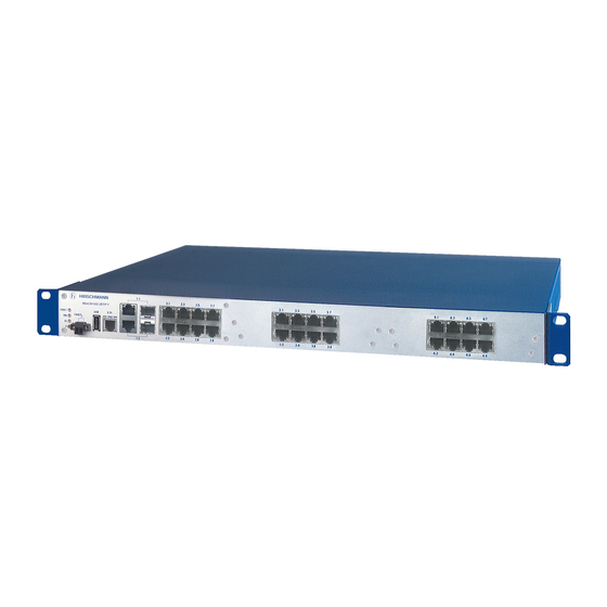
Page 13: Device Views
Device views 1.4.1 Front view MACH104 FAULT V.24 FAULT LED display Device Status elements Signal contact USB interface V.24 interface Ports 1 to 4 1000-Mbit/s Combo Ports Ports 5 to 12 1000-Mbit/s Twisted-Pair Ports with PoE+ Ports 13 to 20 1000-Mbit/s Twisted-Pair Ports with PoE+ Ports 21, 22 10-Gbit/s F/O ports... -
Page 14: Rear View
1.4.2 Rear view Non-heating Connecting the supply voltage appliance socket Table 4: Rear view of device variants: MACH104-16TX-PoEP... MACH104-16TX-PoEP+2X... Non-heating Connecting the supply voltage appliance socket Supply voltage 2 Non-heating Connecting the supply voltage appliance socket Supply voltage 1 Table 5: Rear view of device variants: MACH104-16TX-PoEP-R... -
Page 15: Mach104-16Tx-Poep
1.5.1 MACH104-16TX-PoEP... MACH104-16TX-PoEP+2X... For the supply voltage, the following applies: A power module providing the PoE voltage and the internal supply voltage is integrated in the device. Supply voltage is connected via a non-heating appliance socket. The input voltage is electrically isolated from the housing. 1.5.2 MACH104-16TX-PoEP-R... -
Page 16: 100 Mbit/S F/O Port
The 10/100/1000 Mbit/s twisted pair port offers you the ability to connect network components according to the IEEE 802.3 10BASE-T/100BASE- TX/1000BASE-T standard. This port supports: Autonegotiation Autopolarity Autocrossing (if autonegotiation is activated) 1000 Mbit/s full duplex ... -
Page 17: 10-Gbit/S F/O Port
1000 Mbit/s F/O ports enable the connection of terminal devices or independent network segments according to the IEEE 802.3 1000BASE- SX/1000BASE-LX standard. These ports support: Autonegotiation Full duplex mode Delivery state: autonegotiation activated 1.6.4 10-Gbit/s F/O port This port is an XFP slot. The 10 Gbit/s F/O port allows you to connect network components according to the IEEE 802.3ae 10GBASE-SR/LR standard. -
Page 18: Combo Ports
The following applies to PoE ports: The PoE voltage is supplied via the wire pairs transmitting the signal (phantom voltage). The individual ports (joint PoE voltage) are not electrically insulated from each other. Maximum power available to PoE terminal devices: 240 W Note: We recommend to distribute the PoE power equally between the two port groups (ports 5 to 12 and ports 13 to 20). -
Page 19: Display Elements
SFP is the acronym for Small Form-factor Pluggable which is also commonly known as mini-GBIC (GigaBit Interface Converter). Both Fast Ethernet SFP transceivers and Gigabit Ethernet SFP transceivers are available for your device. XFP transceivers are slightly larger than SFP transceivers. They support 10- Gigabit Ethernet only. -
Page 20: Port State
The following table applies to all device variants: Display Color Activity Meaning Stand-by None Stand-by mode not enabled Green Lights up Standby mode enabled FAULT Signal None The signal contact is closed - it is not contact reporting any detected errors. Lights up The signal contact is open - it is reporting a detected error. -
Page 21: Management Interfaces
The following table applies to all other ports: Display Color Activity Meaning left LED Link status None The device detects an invalid or missing connection. Green Lights up The device detects a valid connection. Flashes 1 time a period The port is switched to stand-by. Flashes 3 times a period The port is disabled. -
Page 22: Usb Interface
Note: You will find the order number for the terminal cable, which is ordered separately, in the Technical Data chapter (see on page 35 “Technical data”). 1.8.2 USB interface The USB socket provides an interface for the local connection of an AutoConfiguration Adapter. -
Page 23: Installation
Installation On delivery, the device is ready for operation. The following procedure has been proven to be successful for the assembly of the device: Unpacking and checking the content of the package Installing SFP/XFP transceivers (optional) MACH104-16TX-PoEP-E..., MACH104-16TX-PoEP+2X-E...: Wiring and assembling the operating voltage ... -
Page 24: Mach104-16Tx-Poep+2X-E
Installing SFP/XFP transceivers (optional) Note: You will find further information under “SFP/XFP transceiver” on page Note: Only use Hirschmann SFP/XFP transceivers. Before attaching an SFP or XFP transceiver, first remove the protective cap of the SFP/XFP transceiver. Push the SFP/XFP transceiver with the lock closed into the socket until it latches audibly in place. -
Page 25: Wiring And Assembling The Signal Contact
WARNING FIRE HAZARD Install an input fuse with a maximum rating of 10 A, characteristic B, into the supply line to the voltage input. Use conductors with a minimum cross-section of 1 mm for the supply line to the voltage input. Non-adherence to these instructions can lead to death, serious physical injury or material damage. -
Page 26: Installing The Device And Grounding
WARNING ELECTRIC SHOCK Never insert sharp objects (small screwdrivers, wires, etc.) into the connection terminals for the signal lines, and do not touch the terminals! Non-adherence to these instructions can lead to death, serious physical injury or material damage. For the signal contact to be connected, make sure the following requirements are met: ... -
Page 27: Mounting On A Flat Surface
Note: The shielding ground of the connectable industrial twisted pair lines is connected to the front panel as a conductor. 2.5.2 Mounting on a flat surface Before operating the device on a flat surface, such as a table, fasten the housing feet supplied at a distance of 2 cm from the corners of the bottom of the device. -
Page 28: Mounting On The Wall
Y LED LS/D A 6.1 Figure 5: Assembly in a switch cabinet with sliding/mounting rails 1 - MACH104-PoEP device 2 - sliding/mounting rail 3 - 19“ switch cabinet MACH104 FAULT V.24 FAULT Figure 6: Mounting the MACH104-PoEP in the 19" cabinet ... -
Page 29: Grounding The Device
You can obtain additional brackets as accessories (see on page 41 “Accessories”). Fasten the device by screwing the brackets to the wall. Figure 7: Vertical mounting on the wall Note: The shielding ground of the connectable industrial twisted pair lines is connected to the front panel as a conductor. -
Page 30: Connecting Network Cables
WARNING ELECTRIC SHOCK This applies to the following device variants only: MACH104-16TX-PoEP-E... MACH104-16TX-PoEP+2X-E... Ground the device before connecting the power supply. Disconnect the grounding last. Exclusively connect SELV circuits with the voltage restrictions in accordance with IEC/EN 60950-1 to the supply voltage connections. Failure to follow these instructions can result in death, serious injury, or equipment damage. -
Page 31: Basic Set-Up
Basic set-up WARNING UNINTENTIONAL OPERATION IN DEVICE Two or more devices configured with the same IP address can cause unpredictable operation of your network. Install and maintain a process that assigns a unique IP address to every device in the network. Failure to follow these instructions can result in death, serious injury, or equipment damage. - Page 32 Stand-by coupling switched off (DIP switch RM and Stand-by: ON) Port 3 = control port, port 4 = coupling port for redundant ring coupling Rapid Spanning Tree: on Installation MACH104-PoEP Release 06 11/2013...
-
Page 33: Maintenance And Service
Maintenance and service When designing this device, Hirschmann largely avoided using wear parts. The parts subject to wear and tear are dimensioned to last longer than the lifetime of the product when it is operated normally. Operate this device according to the specifications (see on page 35 “Technical data”). -
Page 34: Deinstallation
Deinstallation Removing the device To detach the device from the switch cabinet or the wall, remove the screws from the brackets on the device. MACH104 FAULT V.24 FAULT Figure 8: Disassembling the device Deinstalling the SFP/XFP transceivers Pull the SFP/XFP transceiver out of the socket using the opened lock. ... -
Page 35: Technical Data
Technical data General technical data Dimensions See “Dimension drawings” on page 37. Weight MACH104-16TX-PoEP... 4.6 kg MACH104-16TX-PoEP+2X... MACH104-16TX-PoEP-R... 5.2 kg MACH104-16TX-PoEP+2X- R... MACH104-16TX-PoEP-E... 4.4 kg MACH104-16TX-PoEP+2X- E... Operating voltage MACH104-16TX-PoEP... Rated voltage range AC MACH104-16TX-PoEP+2X... 100 V ... 240 V, 50 Hz ... 60 Hz MACH104-16TX-PoEP-R... - Page 36 PoE power Maximum number of Powered 8 × Powered Device (PD) class 4 (30 W) Devices (PDs) 16 × Powered Device (PD) class 0 (15.4 W) Power failure MACH104-16TX-PoEP... > 20 ms bypass MACH104-16TX-PoEP+2X... MACH104-16TX-PoEP-R... MACH104-16TX-PoEP+2X- R... MACH104-16TX-PoEP-E... > 10 ms MACH104-16TX-PoEP+2X- E...
-
Page 37: Dimension Drawings
Dimension drawings 462,6 18.21 0.13 inch 19,3 19,3 0.76 17.48 0.76 EMC and immunity EMC interference immunity IEC/EN 61000-4-2 Electrostatic discharge Contact discharge 6 kV Air discharge 8 kV IEC/EN 61000-4-3 Electromagnetic field 80 MHz ... 3000 MHz 20 V/m IEC/EN 61000-4-4 Fast transients (burst) - Page 38 EMC interference immunity IEC/EN 61000-4-5 Voltage surges This applies to the following device variants only: MACH104-16TX-PoEP-E... MACH104-16TX-PoEP+2X-E... Power line, line / line 0.5 kV Power line, line / ground 1 kV Data line 1 kV This applies to the following device variants only: ...
- Page 39 Product Wave Fiber System Example Fiber code length attenuation for F/O line attenuatio dispersion M-SFP-... length -SX/LC... MM 850 nm 50/125 µm 0-7.5 dB 0-550 m 3.0 dB/km 400 MHz×km -SX/LC... MM 850 nm 62.5/125 0-7.5 dB 0-275 m 3.2 dB/km 200 MHz×km µm -MX/LC...
-
Page 40: Order Numbers
Product Wave Wave Fiber System Example Fiber Dispersion code length length attenuation for F/O attenuati M-SFP- line BIDI... length Type A SM 1310 nm 1550 nm 9/125 0-11 dB 0-20 km 0.4 dB/km 3.5 LX/LC µm ps/(nm×km) Type B SM 1550 nm 1310 nm 9/125 0-11 dB 0-20 km 0.25 19 ps/(nm×km) -
Page 41: Scope Of Delivery
Scope of delivery Device Scope of delivery MACH104-16TX-PoEP... Device MACH104-16TX-PoEP+2X... Terminal block 1 × 2-pin for signal contact 2 × Brackets with fastening screws (pre- mounted) Housing feet, stick-on Power cord 1 × Euro version CD/DVD with manual Installation user manual MACH104-16TX-PoEP-R... - Page 42 Name Order number 2-pin terminal block (50 units) 943 845-010 Bracket for fastening the housing 943 943-001 Long bracket (+ 50 mm) for fastening the housing 943 943-101 (additional) Network management software Industrial HiVision 943 156-xxx OPC Server software HiOPC 943 055-001 10-Gigabit Ethernet XFP transceiver Order number...
- Page 43 Underlying norms and standards Name EN 61000-6-2 Electromagnetic compatibility (EMC) – Part 6-2: Generic standards – Immunity for industrial environments EN 55022 Information technology equipment – Radio disturbance characteristics – Limits and methods of measurement FCC 47 CFR Part 15 Code of Federal Regulations EN 60950-1 Information technology equipment –...
-
Page 44: A Further Support
Contact our support at https://hirschmann-support.belden.eu.com You can contact us in the EMEA region at Tel.: +49 (0)1805 14-1538 E-mail: hac.support@belden.com in the America region at Tel.: +1 (717) 217-2270 E-mail: inet-support.us@belden.com in the Asia-Pacific region at ... - Page 45 Installation MACH104-PoEP Release 06 11/2013...
- Page 46 Installation MACH104-PoEP Release 06 11/2013...
- Page 47 Installation MACH104-PoEP Release 06 11/2013...
Need help?
Do you have a question about the Hirschmann MACH104-PoEP Series and is the answer not in the manual?
Questions and answers