
Subscribe to Our Youtube Channel
Related Manuals for Belden Hirschmann MICE MS20


Summary of Contents for Belden Hirschmann MICE MS20
- Page 1 User Manual Installation Industrial ETHERNET Switch MICE MS20/MS30 MICE MS20 MICE MS30 Installation MS20/MS30 Technical support Release 14 03/2023 https://hirschmann-support.belden.com...
- Page 2 The naming of copyrighted trademarks in this manual, even when not specially indicated, should not be taken to mean that these names may be considered as free in the sense of the trademark and tradename protection law and hence that they may be freely used by anyone. ©...
-
Page 3: Table Of Contents
Contents Important information Safety instructions About this Manual Description General device description Device name and product code Description of the device variants 1.3.1 Number of ports and connections 1.3.2 Media modules 1.3.3 Digital I/O Module MM24 1.3.4 MB20 extender module 1.3.5 SFP Transceiver Ethernet ports 1.4.1 10/100/1000 Mbit/s twisted pair port... - Page 4 Adjusting the DIP switch settings on the basic module (4-pin DIP switch) Adjusting the DIP switch settings on the MS20/MS30-...E... basic module (3-pin DIP switch) Adjusting the DIP switch settings on the MM20-A8A89999SAHH media module Connecting the MM22-T1T1T1T1 PoE media module Terminal block for supply voltage and signal contact 2.9.1 Supply voltage 2.9.2 Signal contacts...
-
Page 5: Important Information
Important information Note: Read these instructions carefully, and familiarize yourself with the device before trying to install, operate, or maintain it. The following notes may appear throughout this documentation or on the device. These notes warn of potential hazards or call attention to information that clarifies or simplifies a procedure. - Page 6 NOTICE NOTICE provides information about procedures that do not involve the risk of injury. Installation MS20/MS30 Release 14 03/2023...
-
Page 7: Safety Instructions
Safety instructions WARNING UNCONTROLLED MACHINE ACTIONS To avoid uncontrolled machine actions caused by data loss, configure all the data transmission devices individually. Before you start any machine which is controlled via data transmission, be sure to complete the configuration of all data transmission devices. Failure to follow these instructions can result in death, serious injury, or equipment damage. - Page 8 Relevant for North America: The device may only be connected to a Class 2 supply voltage that fulfills the requirements of the National Electrical Code, Table 11(b). If the voltage is being supplied redundantly (two different voltage sources), the combined supply voltages must fulfill the requirements of the National Electrical Code, Table 11(b).
- Page 9 Ordinary Location, Class I, Division 2, Non-Hazardous Area, Groups A, B, C, D non-explosive atmosphere Hazardous Location WARNING! The USB connection and the V.24 Interface connection are for temporary MS20/30 switch basic module connection only, for maintenance use. Do not with voltage range type “C”...
- Page 10 Ordinary Location, Non-Hazardous Area, Class I Division 2 non-explosive atmosphere Groups A, B, C, D Hazardous Location WARNING! The USB connection and the V.24 Interface connection are for temporary MS20/30 switch basic module connection only, for maintenance use. Do not with voltage range type “A”...
- Page 11 For use in Hazardous Locations Class I, Division 2, Groups A, B, C, D: Applied standard: ANSI/ISA 12.12.01-2012 CSA C22.2 No. 213-M1987 Only allowed for MS20 or MS30 model No´s. which are individually labelled “FOR USE IN HAZARDOUS LOCATIONS” Non-incendive field wiring circuits must be wired in accordance with the National Electrical Code (NEC), NFPA 70, article 501.
- Page 12 ATEX directive 2014/34/EU – specific regulations for safe operation The following applies to MICE devices and modules for use in hazardous locations: List of standards: EN IEC 60079-0:2018 EN 60079-7:2015 + A1:2018 EN IEC 60079-15:2019 Make sure that the device has the following label: For device type MSxx: II 3G Ex ec nC IIC T4 Gc DEKRA 13ATEX0019 X...
- Page 13 WARNING! The USB connection and the V.24 interface connection are for temporary connection only during maintenance. Do NOT use, connect or disconnect unless the area is known to be non-hazardous. Connection or disconnection in an explosive atmosphere could result in an explosion.
- Page 14 Connectors shall be connected or disconnected exclusively in dead- voltage state. If a relay output (signal contact) is used, the current must be limited to 100 mA resistive load. WARNING! The USB connection and the V.24 interface connection are for temporary connection only during maintenance.
- Page 15 In potentially explosive atmospheres, only use MSxx units that have not previously been operated in other applications at ambient temperatures higher than +45 °C (+113 °F). Make provisions to prevent transient disturbances from exceeding 119 V at the voltage inputs. ...
- Page 16 CAUTION OVERHEATING OF THE DEVICE Verify that all ventilation slots are clear when installing the device. Avoid touching the device while it is operating. Failure to follow these instructions can result in minor injury or equipment damage. Only technicians authorized by the manufacturer are permitted to open the casing.
- Page 17 Only operate the device at the specified ambient temperature (temperature of the ambient air at a distance of up to 2 inches (5 cm) from the device) and at the specified relative humidity. See “General technical data” on page 67. ...
- Page 18 Strain relief Note: If the strain relief is insufficient, there is a potential risk of torsion, contact problems and creeping interruptions. Relieve the connection points of cables and lines from mechanical stress. Design strain reliefs in such a way that they help prevent any mechanical damage to cables, wires or conductors caused by external influences or their own weight.
- Page 19 CE marking The labeled devices comply with the regulations contained in the following European directive(s): 2011/65/EU and 2015/863/EU (RoHS) Directive of the European Parliament and of the Council on the restriction of the use of certain hazardous substances in electrical and electronic equipment.
- Page 20 13. The UKCA conformity declaration will be available to the relevant authorities at the following address: Belden UK Ltd. 1 The Technology Centre, Station Road Framlingham, IP13 9EZ, United Kingdom You find the UKCA conformity declaration as PDF file for downloading on the Internet at: https://www.doc.hirschmann.com/certificates.html...
- Page 21 47 CFR § 2.1077 Compliance Information MS20/MS30 MMxx, MB20 U.S. Contact Information Belden – St. Louis 1 N. Brentwood Blvd. 15th Floor St. Louis, Missouri 63105, United States Phone: 314.854.8000 This device complies with part 15 of the FCC Rules. Operation is subject...
-
Page 22: About This Manual
About this Manual The “Installation” user manual contains a device description, safety instructions, a description of the display, and the other information that you need to install the device. The following manuals are available as PDF files for download on the Internet https://www.doc.hirschmann.com/ ... -
Page 23: Key
The symbols used in this manual have the following meanings: Listing Work step Subheading Installation MS20/MS30 Release 14 03/2023... -
Page 24: Description
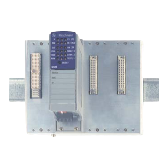
Description General device description MS20 MS30 Figure 1: MICE basic module equipped with media modules 1 - basic module 2 - media module 3 - slot for media module You can choose from a wide range of variants. You have the option to set up your device individually based on different criteria: ... - Page 25 Network management software (for example Industrial HiVision) V.24 interface (locally on the device) The device provides you with a large range of functions, which the manuals for the operating software inform you about. You can download these manuals as PDF files from the Internet at: https://www.doc.hirschmann.com The Hirschmann network components help you ensure continuous communication across all levels of the company.
-
Page 26: Device Name And Product Code
The characteristic values stand for specific product properties. You have numerous options of combining the device characteristics. You can determine the possible combinations using the configurator which is available in the Belden Online Catalog https://catalog.belden.com on the web page of the device. -
Page 27: Description Of The Device Variants
Description of the device variants The industrial ETHERNET series MICE (Modular Industrial Communication Equipment) consists of a basic switch module and the media modules. These devices can be managed. A basic module contains all the functions of this industrial Switch, with the exception of the interfaces to the LAN that is connected. -
Page 28: Number Of Ports And Connections
1.3.1 Number of ports and connections Device versions with 10/100 Mbit/s ports MS20-0800..., MS20-1600..., MS20-2400... Depending on the variant, the MS20 basic modules provide you with the following number of slots for media modules and the following maximum number of connectable network segments: Basic module Number of slots for Max. - Page 29 Figure 3: Interfaces of the MS20-... and MS30-... on the bottom side of the device 1 - Terminal block (Power 2) 2 - DIP switch 3 - Terminal block(Power 1) 4 - USB port 5 - V.24 port 6 - MICE MS20/30 switch basic module with 18 V DC ... 60 V DC voltage range 7 - Terminal block(Power 2) 8 - Terminal block(Power 1)
- Page 30 Figure 4: Interfaces of the MS20-.../MS30-...E... on the bottom side of the device 1 - Terminal block, 6-Pin, for power and signal contact 2 - DIP switch 3 - USB port 4 - V.24 port 5 - MICE MS20/30-...E... switch basic module with 18 V DC ... 60 V DC voltage range / 6-pin Installation MS20/MS30 Release 14 03/2023...
- Page 31 Device variants with 1000 Mbit/s and 10/100 Mbit/s ports MS30-0802..., MS30-1602..., MS30-2402... Depending on the variant, the MS30 basic modules provide you with the following number of slots for media modules and the following maximum number of connectable network segments: Basic module Number of Number of Max.
-
Page 32: Media Modules
1.3.2 Media modules The MICE media modules form the interface of the device to the LAN. They can be attached to Basic module MS20-... Basic module MS30-... They differ with regard to the number of interfaces and the media type. The different interfaces of the media modules provide you with the following interface-specific functions: ... - Page 33 MM2 media modules MM2 media modules TP ports F/O port F/O port F/O port F/O port Module type 10/100 Mbit/ multi-mode multi-mode single- single- 10 Mbit/s 100 Mbit/s mode mode 1300 nm, 1550 nm, 100 Mbit/s 100 Mbit/s MM2 - 4TX1 (- EEC) 4, RJ45 –...
- Page 34 MM3 media modules MM3 media modules TP ports F/O port F/O port F/O port F/O port Module type multi-mode multi-mode single- single- 100 Mbit/s 10 Mbit/s 100 Mbit/s mode mode 1300 nm, 1550 nm, 100 Mbit/s 100 Mbit/s MM3-4TX5 4, M12 –...
- Page 35 MM22-T1T1T1T1 PoE media module The MM22-T1T1T1T1 PoE media module (deeper module design) supports Power over ETHERNET (PoE) according to IEEE 802.3af. It allows the connection and remote supply of IP telephones (Voice over IP), webcams, sensors, printer servers and WLAN access points via 10BASE- T/100BASE-TX, for example.
-
Page 36: Digital I/O Module Mm24
Figure 8: Port assignment 1 - Port 1 (Twisted pair) 2 - Port 2 (Twisted pair) 3 - Port 3 (Twisted pair) 4 - Port 4 (Twisted pair) 1* - Port 1* (SFP slot, can be used as alternative to Port 1) 2* - Port 2* (SFP slot, can be used as alternative to Port 2) 3* - Port 3* (SFP slot, can be used as alternative to Port 3) 4* - Port 4* (SFP slot, can be used as alternative to Port 4) -
Page 37: Sfp Transceiver
1.3.5 SFP Transceiver With the insertion of the SFP transceivers into the SFP slots, F/O ports are available to you. SFP transceivers allow you to use optical interfaces on your device (Fast Ethernet and Gigabit Ethernet SFP transceivers). See “Accessories” on page 86. SFP stands for Small Form-factor Pluggable and is also referred to as mini- GBIC (GigaBit Interface Converter). -
Page 38: 10/100 Mbit/S Poe Port
This port supports: Autonegotiation Autopolarity Autocrossing (if autonegotiation is activated) 100 Mbit/s half-duplex mode, 100 Mbit/s full duplex mode 10 Mbit/s half-duplex mode, 10 Mbit/s full duplex mode Default setting: Autonegotiation activated except for the HIPER-Ring ports: 100 Mbit/s, full duplex. -
Page 39: Pin Assignments
1.4.6 Pin assignments RJ45 10/100 Mbit/s 1000 Mbit/s MDI mode BI_DA+ Positive V TX− BI_DA− Positive V BI_DB+ Negative V — BI_DC+ Positive V — BI_DC− Positive V RX− BI_DB− Negative V — BI_DD+ Negative V — BI_DD− Negative V MDI-X mode BI_DB+ Negative V... -
Page 40: Aui Port
AUI port The housing of the Sub-D plug is electrically isolated from the lower panel of the device. The AUI (Attachment Unit Interface) port offers you the opportunity to connect a device via an AUI cable according to IEEE 802.3. This port supports: ... -
Page 41: Display Elements
Display elements After establishing the operating voltage, the software starts and initializes itself. Afterwards, the device performs a self-test. During this process, various LEDs light up. The process lasts around 60 seconds. Figure 11: Display elements on MS20/MS30 1 - Device status 2 - Display status 3 - Port status Installation MS20/MS30... -
Page 42: Device Status
1.6.1 Device Status This LEDs provide information about conditions that affect the operation of the whole device. P – Power (green LED) Lights up green Internal supply voltage is on. None Internal supply voltage is too low. P1 – Power 1 (green LED) Lights up green Supply voltage 1 is on. -
Page 43: Display Status
If the manual setting is active on the signal contact, then the error display is independent of the setting of the signal contact. 1.6.2 Display status Every media module has 1 LED per port. The meaning of this port status LED depends on the setting on the basic module. -
Page 44: Port Status
2 – PoE status (green/yellow LED) Lights up green The port LEDs of the media modules display the Power over ETHERNET status. None - No PoE port or PoE disabled (PoE status “disabled”). - PoE status “fault”. 3 (green LED) Service LED 1.6.3 Port status... - Page 45 PoE status (green/yellow LED) None No PoE port or PoE disabled; PoE status “fault”. Lights up yellow PoE port searching for terminal device (PD); PoE status “searching”. Lights up PoE port supplying terminal device (PD); PoE status “Delivering Power”. 1 ... 4 – LED TEST (green/yellow LED) None LED defective Flashing green/yellow...
-
Page 46: Installation
Installation The devices have been developed for practical application in a harsh industrial environment. Hirschmann supplies the device ready for operation. Perform the following steps to install and configure the device: Checking the package contents Installing media modules ... -
Page 47: Installing Media Modules
Installing media modules On delivery, the device is ready for operation. You can install and remove media modules during running operation. To attach a media module, first remove the protective cap on the plug. Plug the media module onto the plug. ... - Page 48 Figure 13: Labels for basic modules and media modules 1 - MICE basic module 2 - Label for the name of the module 3 - Label for MAC address of the device 4 - Label for IP address of the device 5 - Label for other entries on your demand 6 - MICE media module 7 - Label for the name of the media module...
-
Page 49: Installing An Sfp Transceiver (Optional)
Installing an SFP transceiver (optional) Prerequisites: Exclusively use Hirschmann SFP transceivers. See “Accessories” on page 86. Figure 14: Installing SFP transceivers: Installation sequence Perform the following work steps: Take the SFP transceiver out of the transport packaging (1). Remove the protection cap from the SFP transceiver (2). ... - Page 50 DIP switch Function Delivery state SW Configuration / OFF: Give the software configuration OFF position (SW configuration DIP Configuration precedence over the DIP switch position. has precedence) In this case, the other switch positions are meaningless. a. You use the “RM” and “Stand-by” switches on the 4-pin DIP switch to switch the following functions on and off (see table 6) b.
-
Page 51: Adjusting The Dip Switch Settings On The Ms20/Ms30
OFF ON Figure 15: 4-pin DIP switch on the MICE basic module MS20-.../MS30-... 1 – Switch 1, function: Redundancy Manager (RM) 2 – Switch 2, function: ring port 3 – Switch 3, function: stand-by 4 – Switch 4, function: Configuration 5 –... - Page 52 c. The "Ringport" switch on the 3-pin DIP switch enables you to select the ring ports for the HIPER-Ring (see table 5) Switch "Ring port" MICE device Ring ports for the HIPER-Ring MS20 Module 1/ port 1 and module 1/ port 2 MS20 Module 1/ port 1 and module 2 / port 1 MS30...
-
Page 53: Adjusting The Dip Switch Settings On The Mm20-A8A89999Sahh Media Module
Adjusting the DIP switch settings on the MM20-A8A89999SAHH media module With the 3-pin DIP switch in the bottom panel of the MM20-A8A89999SAHH media module, you enter settings for the SQE test function and for monitoring the DTE voltage. Note: Before starting operation, check whether the device in question operates the transceiver with or without an SQE test. -
Page 54: Terminal Block For Supply Voltage And Signal Contact
Note: The RPS60/48V EEC power supply unit does not fulfill the requirements according to Germanischer Lloyd, criterion EMC1, relating to conducted emissions on the 230 V AC side. If this requirement must be fulfilled, connect a corresponding power supply unit that fulfills both this requirement and the basic requirements. -
Page 55: Supply Voltage
For more information on the supply with DC voltage power, refer to chapter “Supply voltage” on page 2.9.1 Supply voltage The supply voltage can be connected redundantly. Both inputs are uncoupled. There is no distributed load. With redundant supply, the power supply unit with the higher output voltage supplies the device on its own. - Page 56 2.10.1 Terminal blocks on MS20/MS30-...A... and MS20/ MS30-...C... Products with voltage range A or C (product code position 15—see table have two 4-pin terminal blocks. Note: The maximum accaptable wire size for the terminal blocks is 2.5 mm (0.004 in ) or AWG 12.
-
Page 57: Terminal Blocks On Ms20/Ms30
2.10.2 Terminal block on MS20/MS30-...E... Products with voltage range E (product code position 15 – see table 1 on page 26) have one 6-pin terminal block. +24 V (P1) Relay +24 V (P2) Figure 18: Pin assignment of the 6-pin terminal block 1 - Pin 1 = +24 V (P1) 2 - Pin 2 = Relay 3 - Pin 3 = 0 V... -
Page 58: Installing And Grounding The Device
2.11 Installing and grounding the device 2.11.1 Installing the device onto the DIN rail Verify that there is at least 4 in (10 cm) of space above and below the device. The overall shield of a connected shielded twisted pair cable is connected to the grounding connector on the front panel as a conductor. -
Page 59: Grounding The Device
2.11.2 Grounding the device The lower panel of the device casing is grounded via the DIN rail and optionally by means of the separate ground screw. See figure 2 on page 28. 2.12 Connecting data cables 2.12.1 Twisted Pair ports Note the following general recommendations for data cable connections in environments with high electrical interference levels: ... -
Page 60: Optical Fiber Ports
2.12.2 Optical fiber ports Verify that you connect LH ports only with LH ports, SX ports only with SX ports, and LX ports only with LX ports. Connect the data cables according to your requirements. 2.13 Assembly of the MB20 extender module The MB20 extender module allows you to expand the MS20-1600 and MS30-1602 basic module with two sockets for media modules. -
Page 61: Making Basic Settings
Making basic settings The IP parameters must be entered when the device is installed for the first time. The device provides the following options for configuring the IP addresses: V.24 interface (Command Line Interface) BOOTP DHCP DHCP Option 82 ... - Page 62 USB interface The USB socket has an interface for the local connection of an AutoConfiguration AdapterACA 21-USB. It is used for saving/loading the configuration and for updating the software. Contact number Signal name - Data + Data Ground V.24 interface (external management) ...
-
Page 63: First Login (Password Change)
Log on to the device again with your new password. Note: If you lost your password, then use the System Monitor to reset the password. For further information see: https://hirschmann-support.belden.com/en/kb/required-password-change- new-procedure-for-first-time-login Installation MS20/MS30 Release 14 03/2023... -
Page 64: Maintenance And Service
Maintenance and service When designing this device, Hirschmann largely avoided using high-wear parts. The parts subject to wear and tear are dimensioned to last longer than the lifetime of the product when it is operated normally. Operate this device according to the specifications. ... -
Page 65: Disassembly
Disassembly Removing the device Perform the following work steps: Disconnect the data cables. Disable the supply voltage. Disconnect the terminal blocks. Disconnect the grounding. To remove the device from the DIN rail, press the device downwards and pull it out from under the DIN rail. -
Page 66: Removing An Sfp Transceiver (Optional)
Removing an SFP transceiver (optional) Figure 21: De-installing SFP transceivers: De-installation sequence Perform the following work steps: Open the locking mechanism of the SFP transceiver (1). Pull the SFP transceiver out of the slot via the open locking mechanism (2). -
Page 67: Technical Data
Technical data General technical data Dimensions MS20-0800... 125 mm × 133 mm × 100 mm (4.92 in × 5.24 in × W × H × D 3.94 in) or 125 mm × 133 mm × 140 mm (4.92 in × 5.24 in × 5.51 in MS30-0802... - Page 68 Signal contact Switching current max. 1 A (ambient air temperature ≤ +60 °C (+140 °F)) max. 100 mA (ambient air temperature +60 °C ... +70 °C (+140 °F ... +158 °F)) resistive load as per ATEX, UKEX or IECEx: See notes in chapter “ATEX directive 2014/34/EU –...
- Page 69 Dimension drawings 1.14 5.24 0.16 0.83 0.16 1.14 0.83 5.24 0.16 0.16 1.14 0.83 5.24 0.16 Figure 22: Dimensions of base module MS20 variants and extender module Installation MS20/MS30 Release 14 03/2023...
- Page 70 1.14 0.83 0.16 0.16 5.24 1.14 0.83 0.16 5.24 0.16 1.14 0.83 5.24 0.16 Figure 23: Dimensions of base module MS30 variants and extender module Installation MS20/MS30 Release 14 03/2023...
- Page 71 5.35 inch 2.87 4.53 MM... 24 V MM... 48 V Figure 24: Dimensions of media modules Installation MS20/MS30 Release 14 03/2023...
- Page 72 EMC and immunity EMC interference Standard Marine Railway Sub-station emission applications applications applications applications (trackside) Radiated emission EN 55032 Class A Class A Class A Class A DNV GL Guidelines — EMC 1 — — FCC 47 CFR Part 15 Class A Class A Class A...
- Page 73 EMC interference Standard Marine Railway Sub-station immunity applications applications applications applications (trackside) EN 61000-4-3 80 MHz ... 3000 MHz max. 10 V/m max. 10 V/m max. 20 V/m max. 10 V/m IEEE 1613 80 MHz ... 1000 MHz — — —...
- Page 74 EMC interference Standard Marine Railway Sub-station immunity applications applications applications applications (trackside) Damped oscillation – DC supply connection EN 61000-4-12 line/ground — — — 2.5 kV IEEE C37.90.1 EN 61000-4-12 line/line — — — 1 kV IEEE C37.90.1 Damped oscillation – data line EN 61000-4-12 line/ground —...
- Page 75 Immunity Standard Marine Railway Sub-station applications applications applications applications (trackside) IEC 60068-2-6, test Fc Vibration — 2 Hz ... 13.2 Hz — — with 1 mm (0.04 in) amplitude — — — 2 Hz ... 9 Hz with 3 mm (0.11 in) amplitude 5 Hz ...
- Page 76 Network range Note: The line lengths specified for the transceivers apply for the respective fiber data (fiber attenuation and Bandwidth Length Product (BLP)/ Dispersion). AU port Length of an AUI cable max. 50 m Table 10: AUI port 10/100/1000 Mbit/s twisted pair port Length of a twisted pair segment max.
- Page 77 Product Wave length Fiber System Example for F/O Fiber attenuation BLP/Dispersion code attenuation cable length 1300 nm 9/125 µm 0 dB ... 16 dB 0 km ... 30 km 0.4 dB/km 3.5 ps/(nm×km) (0 mi ... 18.64 mi) 1550 nm 9/125 µm 7 dB ...
- Page 78 Product code Wave length Fiber System attenuation Example for F/O Fiber attenuation BLP/Dispersion M-FAST-SFP-... cable length -LH/LC... 1550 nm 9/125 µm 10 dB ... 29 dB 47 km ... 104 km 0.25 dB/km 19 ps/(nm×km) (29.20 mi ... 64.62 mi) -LH/LC...
- Page 79 Product code Wave length Fiber System Example for F/O Fiber attenuation /Dispersion M-SFP-... attenuation cable length -LX+/LC... 1310 nm 9/125 µm 5 dB ... 20 dB 14 km ... 42 km 0.4 dB/km 3.5 ps/(nm×km) (8.70 mi ... 26.10 mi) -LH/LC...
- Page 80 Product code Wave length Wave length Fiber System Example for F/O Fiber attenuation Dispersion M-SFP-BIDI... attenuation cable length Type A LH/LC EEC LH 1490 nm 1590 nm 9/125 µm 5 dB ... 24 dB 23 km ... 80 km 0.25 dB/km 19 ps/(nm×km) (14.29 mi ...
- Page 81 Basic modules: Power consumption/power output, supply voltage Note: For the extended temperature range, use suitable modules and transceivers. You will identify these components by the “EEC” name extension or the open variant product code “E” (postion 15). Basic module Power consumption Power output Supply voltage MS20-0800...A...
- Page 82 Module Power Power output Operating Order consumpti temperature of the number ambient air MM3-2AUI 3.4 W 11.6 Btu (IT)/h 0 °C ... +60 °C 943 840-101 (+32 °F ... +140 °F) MM3-4FLM4 5.0 W 17.1 Btu (IT)/h 0 °C ... +60 °C 943 760-101 (+32 °F ...
- Page 83 Module Power Power output Operating Order consumpti temperature of the number ambient air MM20-... 0 TX-/4 FX ports 6.8 W 23.2 Btu (IT)/h see table see table MM20-A8A89999... 3.4 W 11.6 Btu (IT)/h see table see table MM20-F4F4F4F4... 5.0 W 17.1 Btu (IT)/h see table see table...
- Page 84 Example: Product code MM30-O7O7O7O7... = media module 1000 Mbit/ s with four Gigabit Ethernet combo ports (4 SFP ports or alternatively 4 TP ports RJ45). This example corresponds to the MM4-4TX/SFP module with the order number 943 010-001. Position Characteristic Charact Property eristic...
- Page 85 Position Characteristic Charact Property eristic value Approvals CE, UL 508, ISA 12.12.01 Class I Division 2 CE, UL 508, ISA 12.12.01 Class I Division 2, GL, ATEX Zone 2 CE, UL 508, GL, EN 50121-4 CE, UL 508, ISA 12.12.01 Class I Division 2, GL, IEC 61850-3, IEEE 1613,EN 50121-4 CE, UL 508, GL, IEC 61850-3, IEEE 1613, EN 50121-4...
- Page 86 Accessories Note that products recommended as accessories may have different characteristics to those of the device, which may limit the application range of the overall system. For example, if you add an accessory with IP20 to a device with IP65, the degree of protection of the overall system is reduced to IP20.
- Page 87 Other accessories Order number ML-MS3 labels 943 768-001 Network management software Industrial HiVision 943 156-xxx OPC server software HiOPC 943 055-001 Underlying technical standards Name EN 50121-4 Railway applications – EMC – Emission and immunity of the signaling and telecommunications apparatus (Rail Trackside) EN 50155 Declaration (Railway) EN 55032...
- Page 88 RFC 768 RFC 1769 SNTP RFC 783 TFTP RFC 1907 MIB2 RFC 791 RFC 1945 HTTP/1.0 RFC 792 ICMP RFC 2131 DHCP RFC 793 RFC 2132 DHCP Options RFC 826 RFC 2236 IGMPv2 RFC 951 BOOTP RFC 2239 MAU-MIB RFC 1112 IGMPv1 RFC 3411 SNMP Framework...
-
Page 89: A Further Support
You find the addresses of our partners on the Internet at http://www.hirschmann.com. A list of local telephone numbers and email addresses for technical support directly from Hirschmann is available at https://hirschmann-support.belden.com. This site also includes a free of charge knowledge base and a software download section. Customer Innovation Center...
Need help?
Do you have a question about the Hirschmann MICE MS20 and is the answer not in the manual?
Questions and answers