Advertisement
Quick Links
User Manual
Installation
MAMMUTHUS Core-layer Switch – MTS8010-Chassis
MAMMUTHUS Power Module – MTM8000-PSU800
MAMMUTHUS Engine Module – MTM8000-Engine
MAMMUTHUS Fan Module – MTM8010-FAN
MAMMUTHUS
MAMMUTHUS
Install MAMMUTHUS switch
Issued in December, 2020
Medium Module
Blank cover
– MTM8000-XXXX
– MTM8000-XXXXCover
https://hirschmann-it.support.belden.com
Technical support
Advertisement

Related Manuals for Belden HIRSCHMANN IT MAMMUTHUS MTS8010-Chassis


Summary of Contents for Belden HIRSCHMANN IT MAMMUTHUS MTS8010-Chassis
- Page 1 MAMMUTHUS Core-layer Switch – MTS8010-Chassis MAMMUTHUS Power Module – MTM8000-PSU800 MAMMUTHUS Engine Module – MTM8000-Engine MAMMUTHUS Fan Module – MTM8010-FAN MAMMUTHUS Medium Module – MTM8000-XXXX MAMMUTHUS Blank cover – MTM8000-XXXXCover Install MAMMUTHUS switch Technical support Issued in December, 2020 https://hirschmann-it.support.belden.com...
- Page 2 The performance characteristics described herein shall be binding only upon the express consent of the parties at the time of signing the contract. This paper is produced by Belden within its capacity. Belden reserves the right to change the contents of this manual without prior notice. Belden does not guarantee the correctness or accuracy of the information in this manual.
- Page 3 Contents Safety Guideline ........................6 About this manual ......................13 Legend ..........................14 Description ........................15 General device description ................15 Device name and product code ............... 22 1.2.1 Basic device ..................... 22 1.2.2 Power module ..................22 1.2.3 Engine module ..................22 1.2.4 Fan module ....................
- Page 4 1.5.6 10GBase-SR/LR/ER SFP+ optical interface attribute ......32 1.5.7 40GBase-SR4/LR4 QSFP+ optical interface attribute ......32 1.5.8 USB interface attribute ................33 1.5.9 SD interface attribute ................33 1.5.10 POE interface attribute ................33 Display unit ......................35 1.6.1 Device status ................... 35 1.6.2 Port status ....................
- Page 5 Technical data ......................51 General technical data ..................51 Dimensional Drawing ..................53 EMC and interference immunity ............... 56 Network range ....................59 Power consumption/power output ..............59 Delivery item, order number and accessories ............60 Basic technical criteria ....................62 A More support ........................
- Page 6 Confirm that there is no component to be repaired in the device. In case of the device damage or fault, it is required to cut off the power supply and return the device to Belden for inspection. Qualification requirements for the operators ...
- Page 7 hazards, so as to reduce the risks on themselves and other persons. The qualified personnel shall receive regular training. Correct use The device is only used for the intended use in the catalog and technical description. It is only allowed to use external units and components as recommended and allowed by the manufacturer, to operate the device.
- Page 8 The diameter of the power line in the voltage input end of the power supply must be at least 0.75 mm (North America: AWG18). The cross section area of the earthing conductor is equal to or more than the cross section area of the power line. The power cable applicable for voltage, current and physical load shall be used.
- Page 9 Special conditions for safe use Measures will be taken to prevent the instantaneous interference exceeding 140% of the rated voltage in the voltage input end. Shielded earthing The shielded earthing module of the twisted-pair cables is used as the conductor for connection to the front panel.
- Page 10 Device enclosure Only the technician authorized by the manufacturer can be allowed to open the enclosure. Keep the air vent unblocked, to ensure good air circulation. Ensure that there will be he space of at least 3.94-inch (10cm) in front of the air vent of the enclosure.
- Page 11 Hirschmann Automation and Control GmbH Stuttgarter Str. 45-51 72654 Neckartenzlingen Germany www.belden.com Warning! This is Category A device, which might interfere with the living area. In this case, the operator might be required to take proper measures. Warning! When Ethernet cable is used in the industrial environment, it must be shielded.
- Page 12 LED or laser component LED or laser component conforming to IEC 60825-1 (2014): Category 1 laser product Category 1 LED product FCC notes: This device conforms to Part 15 of FCC Rules. When operating the device, it is required to meet the following two conditions: (1) this device will not have any harmful interference;...
- Page 13 About this manual This "installation" user manual consists of device description, safety guideline, display description and other information required for device installation. Install MAMMUTHUS switch Issued in December, 2020...
- Page 14 Legend The symbols used in this Manual have the following meanings: • • Itemized list Work steps Subtitle Install MAMMUTHUS switch Issued in December, 2020...
- Page 15 Description General device description MTS8010 switch uses the main control and exchange separation technology leading in the industry. The whole machine can provide the deployment capability of at most 448 10G interfaces or 128 40G high-density ports. Provide multiple physical resource virtualization technologies, such as 1:N, N:1, raise the SDN compatible machine concept for the first time, and realize the integration of SDN deployment with the functions of common switch.
- Page 16 Power module You can choose 1 to 4 power modules with the same input voltage: Power module is supplied as the accessory. Refer to "Order Number" on Page 21. Engine module Engine module is the most important and necessary board card in MTS8010 switch, and serves as the control center of the device.
- Page 17 1:1 backup. Engine module is supplied as the accessory. Refer to "Order Number" on Page 21. Fan module Provide 2 fan slots for the rear panel of the switch and use at least 2 fan modules. Fan module is supplied as the accessory. Refer to "Order Number"...
- Page 18 MTM8000-16X4Q-S MTM8000-16X-S Install MAMMUTHUS switch Issued in December, 2020...
- Page 19 MTM8000-24T24F2X-S MTM8000-48F2X-S MTM8000-48T2X-S MTM8000-48TP2X-S Install MAMMUTHUS switch Issued in December, 2020...
- Page 20 MTM8000-52X-A MTM8000-SF-16F16X-S MTM8000-SF-24F8X-S Install MAMMUTHUS switch Issued in December, 2020...
- Page 21 MTM8000-SF-A MTM8000-SF-S The front panel of the switch has provided multiple types of different interface patterns available for the user choice, to meet the demands in various application scenarios. Medium module is supplied as the accessory. Refer to "Order Number" on Page 21. Install MAMMUTHUS switch Issued in December, 2020...
- Page 22 Device name and product code The device name corresponds to the product code. 1.2.1 Basic device Order Product code Description number 942999791 MTS8010-Chassis The rack-type 40G core-layer switch, 4 × power module slots, 2 × engine module slots, 10 × medium module slots, 2 ×...
- Page 23 MTM8010-FAN Fan module is mandatory for MTS8010 942999797 switch, and supports hot plugging. Each MTS8010 switch has 2 fan slots, and two 2 fan modules must be installed to guarantee normal operation of the system. 1.2.5 Medium module Order Product code Description number MTS8010 medium module;...
- Page 24 Hybrid card, standard switch fabric MTM8000-SF- 942999796 with 16 × 100M/1000M SFP slots, 16F16X-S 16 × 1/10G SFP+ slots 1.2.6 Blank cover Order Product code Description number MTM8000- Blank cover of the medium module 942999815 ModuleCover of the switch MTM8000- Blank cover of the engine module of 942999816 EngineCover...
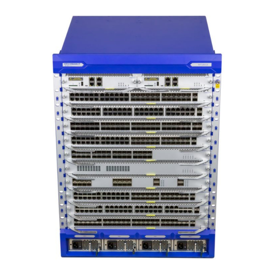
- Page 25 Device view 1.3.1 MTS8010-Chassis Front view Slot 0 and 1 of engine module Slot 0 of medium module Slot 1 of medium module Slot 2 of medium module Slot 3 of medium module Slot 4 of medium module Slot 5 of medium module Slot 6 of medium module Slot 7 of medium module Slot 8 of medium module...
- Page 26 Anti-static bracelet socket Handle of the machine case Rear view Slot 0 of fan module Slot 1 of fan module Air outlet Grounding stud Upper cabinet screw hole Install MAMMUTHUS switch Issued in December, 2020...
- Page 27 1.3.2 Power module AC power socket Power switch Anti-stripping slider for power line Power module unlocking button Power handle Power status indicator 1.3.3 Engine module Anti-loosening screw Board card puller SD card slot Install MAMMUTHUS switch Issued in December, 2020...
- Page 28 USB interface Function port Board card label slot Function status indicator Reset button 1.3.4 Fan module Install the handle Fan status indicator Air outlet of the fan Fan label Anti-loosening screw 1.3.5 Medium module Install MAMMUTHUS switch Issued in December, 2020...
- Page 29 Printed circuit board Anti-loosening screw Board card puller Function port Board card label slot Status indicator 1.3.6 Blank cover Schematics of Blank cover of the engine module Schematics of the Blank cover of the medium module Install MAMMUTHUS switch Issued in December, 2020...
- Page 30 Schematics of Blank cover of the power module Power supply You may use the power module to supply voltage for the device: See "Power Module" on Page 21 for the information related to the connecting power voltage. Install MAMMUTHUS switch Issued in December, 2020...
- Page 31 Device port attribute You may use twisted-pair cable or optical fiber (F/O) to connect the terminal devices and other network segments to this device and medium module port. 1.5.1 Console port attribute Attribute Description Interface standard Asynchronous EIA/TIA-232 Connector type RJ45 Baud rate 9600- 115200 (default as...
- Page 32 1.5.4 10GBase-T RJ45 electric interface attribute Attribute Description Interface standard IEEE 802.3an、IEEE802.3ab 、IEEE802.3u Connector type RJ45 Working mode 10Gbps (full duplex) 1000Mbps (half duplex/full duplex) Auto-negotiation Maximum transmission 100m distance Connected cable Cat. 6e and above shielded twisted pairs (S/FTP) 1.5.5 1000Base-X SFP optical interface attribute Attribute...
- Page 33 Attribute Description Working mode 40Gbps full duplex Support QSFP+ interface Support 40GBase-SR4/LR4 Connected cable Single mode optical fiber of multimode optical fiber 1.5.8 USB interface attribute Attribute Description Interface standard USB2.0 Interface type USB Type A Working mode 1.5Mbps, 12Mbps and 480Mbps Host, supporting hot plugging and controlled (command mode) hot...
- Page 34 Attribute Description 1000base-T. Cable For more information, see "User Manual for Command Line Interface". You can download this manual from Hirschmann IT product page: https://hirschmann-it.support.belden.com Install MAMMUTHUS switch Issued in December, 2020...
- Page 35 Display unit After the setting of the power voltage, the software will automatically start and be initialized. Then the device will start the self-check. During this course, the LED indicator will be ON. 1.6.1 Device status These LEDs provide the condition information influencing the operation of the whole device.
- Page 36 1.6.2 Port status These LEDs provide the related information of the ports. Category of Name of Color of Status the indicator indicator indicator Flash: indicates that there is data sent out of the serial RJ45 self- port supplied with OFF: indicates that there is no data sent out of the yellow LED serial port Serial port...
- Page 37 Category of Name of Color of Status the indicator indicator indicator If the port LED indicator 3 is ON, then every interface indicator indicates that the status of the third (3rd) 10GE interface in this interface. If the port LED indicator 4 is ON, then every interface indicator indicates that the status of the fourth (4th) 10GE interface in this interface.
- Page 38 Management interface 1.7.1 DC0 interface (external management) The serial interface is provided on RJ45 socket (DC0 interface), to realize the local connection of external management station (VT100 terminal or PC with corresponding terminal simulation), thus allowing you to build the connection with the command line interface CLI and system monitor.
- Page 39 Installation These devices are developed for the use in the commercial environment. At the time of delivery, the devices are ready for being put into operation. Execute the following steps to install and configure the device: Unpacking and inspection ...
- Page 40 Device installation and earthing You may use the following options to install the device: Installation in the switch cabinet Installation on the vertical and flat surface Warning Electric shock Such devices are only installed in the switch cabinet or in the restricted operation field, and can be accessed only by the maintenance personnel.
- Page 41 hot. Measure the depth of 19" cabinet, to facilitate easy insertion of all connection circuits. Install MAMMUTHUS switch Issued in December, 2020...
- Page 42 Operate in the following steps: Assemble the sliding or mounting guide rail into 19" switch cabinet according to the regulations of the manufacturer. The device is installed on the guide rail of the switch cabinet. Tighten the bracket onto the switch cabinet with the screws, to fix the device.
- Page 43 Insert SFP transceiver into the slot, till it is locked. Install MAMMUTHUS switch Issued in December, 2020...
- Page 44 Operate the device Operate in the following steps: Fix the connector on the device by the screws. You may check the tightening torque stipulated in "General Technical Data" on Page 50. Enable the power voltage. Connecting the data cable In the environment with high electrical interference, notice the following general suggestions related to the data cable connection: ...
- Page 45 Carry out the basic setting Note: Configuring two or more devices with the same PI address might cause the network to be incapable of expected operation. Install and maintain one program to distribute a unique IP address for every device in the network. When installing the device for the first time, input IP parameters.
- Page 46 Monitor the ambient air temperature Operate this device below the designated maximum ambient air temperature. Refer to "General Technical Data" in Page 50. The ambient air temperature is the air temperature 2 inch (5cm) from the device, depending on the installation conditions of the device, for example, the distance between such device and other device or other object, and the output of the adjacent device and so on.
- Page 47 You can log in Hirschmann IT product page: https://hirschmann-it.support.belden.com to check the information and download the software. Regularly check whether the ventilation channel in the device is blocked according to the contamination degree in the operating environment.
- Page 48 Remove Remove the power module Operate in the following steps: Wear the anti-static bracelet, and confirm that the anti-static bracelet can be reliably earthed. Turn off the power switch. Unlock the power cable, and unplug the power line. ...
- Page 49 Seal the SFP transceiver with protective cover. Remove engine or medium module Operate in the following steps: Untighten the screws on the front panel of the engine or medium module. Press the locking lever outward to release the locking of the engine or medium module (steps 1 and 2).
- Page 50 untighten the screws on the bracket of the device. Install MAMMUTHUS switch Issued in December, 2020...
- Page 51 Technical data General technical data Basic devices Refer to "Dimensional Drawing" on Page Size 32.48kg (machine Weight frame) Rated voltage 100 VAC ... 240 Power supply range ,50 Hz ... 60 Hz Maximum AWG12 (2.5 mm conductor diameter Device earthing Tightening torque 3.5~6.1 lb-in Protective earthing...
- Page 52 Engine module Refer to "Dimensional Drawing" on Page 52 Size Weight MTM8000-Engine 1.48Kg Installation Tightening torque 3.5~5.2 lb-in (0.4~0.6 Nm) power module Installation of the Tightening torque 3.5~5.2 lb-in (0.4~0.6 Nm) cover plate Fan module Refer to "Dimensional Drawing" on Page 52 Size 2.60Kg Weight...
- Page 53 Dimensional Drawing Basic devices Install MAMMUTHUS switch Issued in December, 2020...
- Page 54 Power module Engine module Install MAMMUTHUS switch Issued in December, 2020...
- Page 55 Fan module Install MAMMUTHUS switch Issued in December, 2020...
- Page 56 Medium module EMC and interference immunity EMC interference emission Standard application EN 55032 Class A DNV GL guideline — FCC 47 CFR Part 15 Class A EN 61000-6-4 Compliance EN 55032 AC/DC power line Class A DNV GL guideline AC/DC power line —...
- Page 57 EMC interference immunity Standard application Electromagnetic field EN 61000-4-3 80 MHz ... 1000 MHz 10 V/m 1000 MHz ... 6000 MHz 3 V/m IEEE 1613 80 MHz ... 1000 MHz — Fast transient (burst) EN 61000-4-4 AC/DC power line ±2 kV IEEE C37.90.1 EN 61000-4-4 Data line...
- Page 58 EMC interference immunity Standard application Damped vibration – AC/DC power line EN 61000-4-12 Line/Earth — IEEE C37.90.1 EN 61000-4-12 Line/Line — IEEE C37.90.1 Damped vibration - Data line EN 61000-4-12 Line/Earth — IEEE C37.90.1 EN 61000-4-12 Line/Line — Pulsed magnetic field EN 61000-4-9 —...
- Page 59 Network range Note: the line length specified for the transceiver applies to the related optical fiber data (optical fiber attenuation and BLP/dispersion). Product code Optical fiber BLPc/dispersio Mode Wavelength F/O cable length example MTS-SFP-10G-... attenuation -SR/LC... 850 nm 300 m (> 5.1 dB link budget at 3.0 dB/km 850nm ) -LR/LC...
- Page 60 Delivery item, order number and accessories Delivery item Quantity Article Device General Safety Guideline Bracket Order number MAMMUTHUS switch MTS8010-Chassis 942 999 791 MAMMUTHUS power module MTM8000-PSU800 942 999 803 MAMMUTHUS fan module MTM8010-FAN 942 999 797 MAMMUTHUS engine module MTM8000-Engine 942 999 802 MAMMUTHUS medium module...
- Page 61 MTS-SFP-10G-ER/LC 942 999 853 MTS-SFP-10G-TX/RJ45 942 999 867 40G SFP module Order number MTS-SFP-40G-SR/LC 942999863 MTS-SFP-40G-LR/LC 942999864 a. You may find more information about the certificate on the Hirschmann IT product webpage (https://hirschmann-it.support.belden.com). Install MAMMUTHUS switch Issued in December, 2020...
- Page 62 Basic technical criteria Name FCC 47CFR Part 15 Code of Federal Regulations IEC 60825-1 Laser product safety EN 55032 Electromagnetic compatibility of multimedia equipment - Emission requirements EN 62368-1 Information technology equipment - Safety - Part 1: General requirements EN 61000-3-2 Electromagnetic compatibility (EMC) –...
- Page 63 The equipment usually meets the technical standard mentioned in the latest version. Only when the device enclosure is attached with the certification mark, can it mean that the device has passed the specific standard certification. Install MAMMUTHUS switch Issued in December, 2020...
- Page 64 A More support Technical problems In case of any technical problem, contact your local Hirschmann IT distributor or Belden. You may search the addresses of our partners from the website: https://hirschmann-it.support.belden.com. For the local telephone number and email list of Hirschmann IT direct technical support, visit: https://hirschmann-it.support.belden.com。...
- Page 65 Install MAMMUTHUS switch Issued in December, 2020...
Need help?
Do you have a question about the HIRSCHMANN IT MAMMUTHUS MTS8010-Chassis and is the answer not in the manual?
Questions and answers