Table of Contents
Advertisement
Quick Links
Advertisement
Table of Contents

Related Manuals for Belden HIRSCHMANN MAMMUTHUS MTS2948X6Q-A


Summary of Contents for Belden HIRSCHMANN MAMMUTHUS MTS2948X6Q-A
- Page 1 User Manual Installation MAMMUTHUS CORE LAYER SWITCH – MTS2948X- 6Q-A MAMMUTHUS POWER MODULE– MTM290-PSU250 MAMMUTHUS FAN MODULE – MTM2900-FAN Installation MAMMUTHUS Technical Support https://hirschmann-it-support.belden.com Release 02 08/2023...
- Page 2 The performance features described here are binding only if they have been expressly agreed when the contract was made. This document was produced by Belden according to the best of the company's knowledge. Belden reserves the right to change the contents of this document without prior notice. Belden can give no guarantee in respect of the correctness or accuracy of the information in this document.
-
Page 3: Table Of Contents
Contents Important information ..............6 Safety instructions ............... 8 About this manual ............... 14 Key ....................15 Description ..............16 General device description ...................... 16 Device name and product code ....................18 1.2.1 Basic device ......................... 18 1.2.2 Power module ......................18 1.2.3 Fan module ........................ - Page 4 Installation ..............30 Checking the package contents ....................30 Installing the power module (optional) ..................30 2.2.1 Installing the power module ..................30 Installing and grounding the device ..................32 2.3.1 Installing the device in the switch cabinet ..............32 2.3.2 Installing the device on a vertical flat surface ...............
- Page 5 Underlying technical standards ........59 Further support ............... 60 Installation MAMMUTHUS Release 02 08/2023...
-
Page 6: Important Information
Important information Note: Read these instructions carefully, and familiarize yourself with the device before trying to install, operate, or maintain it. The following notes may appear throughout this documentation or on the device. These notes warn of potential hazards or call attention to information that clarifies or simplifies a procedure. Symbol explanation ... - Page 7 NOTICE NOTICE provides information about procedures that do not involve the risk of injury. Installation MAMMUTHUS Release 02 08/2023...
-
Page 8: Safety Instructions
Safety instructions WARNING UNCONTROLLED MACHINE ACTIONS To avoid uncontrolled machine actions caused by data loss, configure all the data transmission devices individually. Before you start any machine which is controlled via data transmission, be sure to complete the configuration of all data transmission devices. Failure to follow this instruction can result in death, serious injury, or device damage. - Page 9 Verify serial number of delivered products to make sure it is unified with a hardcopy serial number list provided by the manufacturer. If it is necessary, please contact Belden representative to obtain a softcopy serial number list from the manufacturer for double check.
- Page 10 Requirements for connecting the supply voltage Before connecting the supply voltage, always verify that the requirements listed are complied with. The following requirements apply without restrictions: All variants All of the following requirements are complied with: The supply voltage corresponds to the voltage specified on the type plate of the device.
- Page 11 ESD guide The modules are equipped with electrostatic sensitive components. If the connection is touched, these sensitive components can be damaged or their service life shortened due to electric field or charge balance effects. You may find information about electrostatic hazard components in DIN EN 61340-5-1 (2007-08) and DIN EN 61340-5-2 (2007-08).
- Page 12 Germany You find the EU conformity declaration as PDF file for downloading on the Internet at: https://catalog.belden.com Warning! This is a class A device. This device can cause interference in living areas, and in this case the operator may be required to take appropriate measures.
- Page 13 Supplier's Declaration of Conformity 47 CFR § 2.1077 Compliance Information MAMMUTHUS U.S. Contact Information Belden – St. Louis 1 N. Brentwood Blvd. 15th Floor St. Louis, Missouri 63105, United States Phone: 314.854.8000 This device complies with part 15 of the FCC rules.
-
Page 14: About This Manual
Documentation mentioned in the “User Manual Installation” that is not supplied with your device as a printout can be found as PDF files for downloading on the Internet at: https://catalog.belden.com Installation MAMMUTHUS Release 02 08/2023... -
Page 15: Key
The symbols used in this manual have the following meanings: Listing Work step Subheading Installation MAMMUTHUS Release 02 08/2023... -
Page 16: Description
Description General device description MTS2900 switch provides excellent port density and switching performance, with enhanced L2 / L3 feature set. It can support data center level network and provides high flexibility configuration options and Open Flow support. It can be used as a core switch, combined with MTS2600\MTS2700\MTS2800 to form a compact data network solution. - Page 17 Power module You can choose 1 or 2 power modules with the same input voltage. Power modules are provided as accessories. See “Order number” on page Fan module The rear panel of the switch provides 4 fan slots, equipped with standard 4 fan modules.
-
Page 18: Device Name And Product Code
Device name and product code The device name corresponds to the product code. 1.2.1 Basic device Order number Product code Description 942999824 MTS2948X-6Q-A 1 × rack-mounted 10 Gbit/s core layer switch; 48 × 1/10 Gbit/s SFP+ slot; 6 × 40 Gbit/s QSFP+ slot; 2 ×... -
Page 19: Device Views
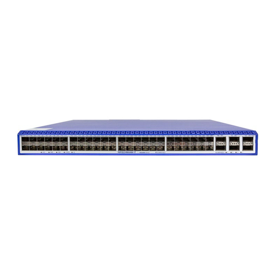
Device views 1.3.1 MTS2948X-6Q-A Figure 1: Front view of the Basic Device Port Status LED (1/10 Gbit/s optical port) The device status LEDs from left to right are as follows: SYS: System indicator PWR: Power indicator FAN: Fan indicator STACK: Stack indicator ID: ID indicator Port status LED (40 Gbit/s optical port) BREAK OUT indicator... - Page 20 Figure 2: Rear view of the Basic Device DC0 interface CONSOLE port Micro USB (CONSOLE port ) CONSOLE port USB interface The device status LEDs from top to bottom are as follows: SYS: System indicator FAN: Fan indicator STACK: Stack indicator USB: USB indicator ID: ID indicator Reset button (press and hold for 5 seconds to restart the machine)
-
Page 21: Power Module
1.3.2 Power module Figure 3 Rear View of the Power Module : Air outlet of the Power Module Handle Power status LED AC power socket Fixed card buckle Installation MAMMUTHUS Release 02 08/2023... -
Page 22: Fan Module
1.3.3 Fan module Figure 4: Rear View of the Fan Module Air outlet of the Fan Module Fixed card buckle Installation MAMMUTHUS Release 02 08/2023... -
Page 23: Power Supply
Power supply You may use the power module to supply voltage to the device. For information about connecting supply voltage, see “Power module” on page Installation MAMMUTHUS Release 02 08/2023... -
Page 24: Ethernet Ports
Ethernet ports You can use fiber optic (F/O) to connect end devices and other network segments to the device and the media module ports. 1.5.1 1/10 Gbit/s F/O port This port is an SFP+ slot. The port allows you to connect network components according to IEEE 802.3. This port supports: Full duplex ... -
Page 25: Out-Of-Band Management Port
The port allows you to manage the device and upload configuration through the following protocols: SNMP Telnet See “Command line interface user manual” for more information. The manual is available for download on the Internet: https://catalog.belden.com Installation MAMMUTHUS Release 02 08/2023... -
Page 26: Display Elements
Display elements After the supply voltage is set up, the Software starts and initializes the device. Afterwards, the device performs a self-test. During this process, various LEDs light up. 1.6.1 Device state These LEDs provide information about the conditions which affect the operation of the whole device. - Page 27 LEDs on the rear panel of the device Indicator Indicator Indicator type Status name color Quick flashing (flashing 5 times per second): indicating hardware starts to work after power on. System Status Slow flashing (flashing 1 time per 2 seconds): Green indicating the system is working normally.
-
Page 28: Port Status
1.6.2 Port Status These LEDs provides port information. Indicator type Indicator Indicator color Status name Serial port RJ45 self- Flashing: indicating data sending in serial port. indicator contained OFF: indicating no data sending in serial port. yellow LED RJ45 build-in Flashing: indicating data receiving in serial port. -
Page 29: Management Interfaces
Management interfaces 1.7.1 DC0 interface (external management) The serial interface is provided on RJ45 socket (DC0 interface), which can realize the local connection of external management station (VT100 terminal or PC with corresponding terminal emulation). This enables you to set up a connection to the CLI (Command Line Interface) and to the System Monitor. -
Page 30: Installation
Installation These devices have been developed for practical application in a harsh industrial environments. On delivery, the equipment is ready for operation. Perform the following work steps to install and configure the device: Checking the package contents Installing the power module (optional) ... - Page 31 Figure 5: Installing the power module Installation MAMMUTHUS Release 02 08/2023...
-
Page 32: Installing And Grounding The Device
Installing and grounding the device Perform the following work steps: Installing the device This device offers the following two installation options: Option 1: Installing the device in the switch cabinet. In this way, the device is placed horizontally. Refer to 2.3.1 Installing the device in the switch cabinet. - Page 33 Prerequisites: Install the device in a 19" switch cabinet by means of the slide or mounting rails. It improves the stability of the device in an environment affected by vibrations. For more information about the slide or mounting rails and how to install them, please contact the switch cabinet manufacturer.
- Page 34 Rear support brackets are provided as delivery items with the device. See “Delivery items” on the page 57. You can choose to install the brackets either on the rear posts or on the front posts based on the installation environment, such as the depth of the cabinet.
- Page 35 Attach the 2 rack ears at the front of the device to the posts of the switch cabinet using 4 mounting screws. Figure 9: Installed device on a 19" switch cabinet with the rear support brackets installed on the rear post Installation MAMMUTHUS Release 02 08/2023...
-
Page 36: Installing The Device On A Vertical Flat Surface
2.3.2 Installing the device on a vertical flat surface WARNING FIRE RISK In case of vertical installation, install the device in the fireproof enclosure. Failure to follow this instruction can result in death, serious injury, or device damage. Perform the following work steps: ... -
Page 37: Grounding The Device
2.3.3 Grounding the device WARNING ELECTRIC SHOCK Ground the device before connecting any other cables. Failure to follow this instruction can result in death, serious injury, or device damage. The device has the connection of the protective grounding wire. The device is grounded by the grounding screw and the power socket. Perform the following work steps: ... -
Page 38: Installing An Sfp Transceiver (Optional)
Installing an SFP transceiver (optional) Prerequisite: Exclusively use Hirschmann IT SFP transceivers. See “Accessories” on the page 57. Perform the following work steps: Take the SFP transceiver out of the transport packaging, refer to Figure 12 below. Remove the protection cap from the SFP transceiver, refer to Figure 13 below. -
Page 39: Operating The Device
Operating the device Perform the following work step: Connect the power supply cable, refer to Figure 15 below. Enable the power supply. Figure 15: Connect the power supply Connecting data cables Note the following general recommendations for data cable connections in environments with high electrical interference levels: Keep the length of the data cables as short as possible. -
Page 40: Filling Out The Inscription Label
Filling out the inscription label The information field for the MAC address helps you identify your device. Installation MAMMUTHUS Release 02 08/2023... -
Page 41: Making Basic Settings
Making basic settings Note: 2 or more devices configured with the same IP address can cause the network’s failure to function as expected. Install and maintain a process that assigns a unique IP address to each device in the network. The IP parameters must be entered when the device is installed for the first time. -
Page 42: Monitoring The Ambient Air Temperature
Monitoring the ambient air temperature Operate the device below the specified maximum ambient air temperature exclusively. See “General technical data” on page 47. The ambient air temperature is the temperature of the air at a distance of 5 cm (2 in) from the device. -
Page 43: Maintenance And Service
Check regularly whether there is an updated version of the software that provides you with additional benefits. You find information and software downloads on the Hirschmann IT product pages on Internet (https://catalog.belden.com/). Depending on the degree of pollution in the operating environment, check at ... -
Page 44: Disassembly
Disassembly Removing the power module Perform the following work steps: Pull the power module out of the power module slot. Blank the power module slot on the device using the cover plate. Removing the fan module Perform the following work steps: ... -
Page 45: Removing An Sfp Transceiver
Removing an SFP transceiver Perform the following work steps: Release the lock and pull the SFP transceiver out of the device slot. Figure 16: Releasing the lock Use a protective cover to blank the SFP transceiver. Figure 17: Installing the Protective Cover Installation MAMMUTHUS Release 02 08/2023... -
Page 46: Removing The Device
Removing the device WARNING ELECTRIC SHOCK Please disconnect all other cables before disconnecting the ground wire. Failure to follow these instructions can result in death, serious injury, or device damage. Perform the following work steps: Disconnect the data cables. ... -
Page 47: Technical Data
Technical data General technical data Basic device Dimensions See “Dimension drawings” on the page 49. W × H × D Weight 10.8 kg (23.8 lb) Power supply Rated voltage range 192 V AC ... 240 V AC , 50 Hz … 60 Hz Maximum conductor diameter AWG12 (2.5 mm) Back-up fuse... - Page 48 Fan module Size See “Dimension drawings” on page 51. Weight MTM2900-FAN 0.2 kg (0.4 lb) Install fan module Tightening torque 0.2 Nm … 0.3 Nm (2.0 lb-in … 3.1 lb- Mount cover plate Tightening torque 0.2 … 0.3 Nm (2.0 lb-in … 3.1 lb-in) Installation MAMMUTHUS Release 02 08/2023...
-
Page 49: Dimension Drawings
Dimension drawings Basic Device Installation MAMMUTHUS Release 02 08/2023... - Page 50 Power module Installation MAMMUTHUS Release 02 08/2023...
- Page 51 Fan module Installation MAMMUTHUS Release 02 08/2023...
-
Page 52: Emc And Immunity
EMC and immunity EMC interference emission Standard application EN 55032 Class A DNV GL Guide — FCC 47 CFR Part 15 Class A EN 61000-6-4 Fulfilled EN 55032 AC/DC Power Line Class A DNV GL Guide AC/DC Power Line — FCC 47 CFR Part 15 AC/DC Power Line Class A... - Page 53 EMC interference immunity Standard application Electromagnetic field EN 61000-4-3 80 MHz ... 1000 MHz 10 V/m 1000 MHz ... 6000 MHz 3 V/m IEEE 1613 80 MHz ... 1000 MHz — Fast transient (burst) EN 61000-4-4 AC/DC Power Line ±2 kV IEEE C37.90.1 EN 61000-4-4 Data cable...
- Page 54 EMC interference immunity Standard application Damped vibration - AC/DC Power Line EN 61000-4-12 Line / ground — IEEE C37.90.1 EN 61000-4-12 Line / Line — IEEE C37.90.1 Damped oscillation - data cable EN 61000-4-12 Line / ground — IEEE C37.90.1 EN 61000-4-12 Line / Line —...
-
Page 55: Network Range
Network range Note: The line lengths specified for the transceivers apply for the respective fiber data (fiber attenuation and Bandwidth Length Product (BLP)/Dispersion). Product code Mode Wave F/O cable length example Optical BLPc/ MTS-SFP-10G- length attenuation dispersion -SR/LC... 850 nm 300 m (>... - Page 56 Name Maximum power consumption Power output 1G SFP+ MTS-SFP-1G-BIDI-TypeA-LX/LC 3.5 Btu (IT)/h < < MTS-SFP-1G-BIDI-TypeB-LX/LC 3.5 Btu (IT)/h < < MTS-SFP-1G-LH+/LC 3.5 Btu (IT)/h < < MTS-SFP-1G-LH/LC 3.5 Btu (IT)/h < < MTS-SFP-1G-LX+/LC 3.5 Btu (IT)/h < < MTS-SFP-1G-LX+/LC-1550 3.5 Btu (IT)/h <...
-
Page 57: Scope Of Delivery, Order Number, And Accessories
Scope of delivery, order number, and accessories Delivery items Quantity Articles 1× Device 1× General safety guidelines 2× Rack ear 2× Rear support bracket Order number MAMMUTHUS SWITCH 942 999-824 MAMMUTHUS POWER MODULE 942 999-822 MAMMUTHUS FAN MODULE 942 999-823 Accessories ... - Page 58 MTS-SFP-10G-TX/RJ45 942 999-867 40G SFP module Order number MTS-SFP-40G-SR/LC 942 999-863 MTS-SFP-40G-LR/LC 942 999-864 You may access more information about certificates here: https://catalog.belden.com/ Installation MAMMUTHUS Release 02 08/2023...
- Page 59 Underlying technical standards Name Description FCC 47CFR Part 15 Code of Federal Regulations IEC 60825-1 Safety of Laser Products EN 55032 Electromagnetic compatibility multimedia equipment. Emission Requirements EN 55035 Electromagnetic compatibility multimedia equipment. Immunity Requirements EN 62368-1 Information technology equipment - Safety - Part 1: General requirements EN 61000-3-2 Electromagnetic compatibility (EMC) - Part 3-2: Threshold - Threshold for harmonic current (equipment input current ≤16 A per phase)
- Page 60 For technical questions, please contact any Hirschmann IT dealer in your area or Hirschmann IT directly You find the addresses of our partners on the Internet at https://catalog.belden.com/ A list of local telephone numbers and email addresses for technical support directly from Hirschmann IT is available at https://catalog.belden.com/...
- Page 61 Installation MAMMUTHUS Release 02 08/2023...
Need help?
Do you have a question about the HIRSCHMANN MAMMUTHUS MTS2948X6Q-A and is the answer not in the manual?
Questions and answers