Table of Contents
Advertisement
Quick Links
Advertisement
Table of Contents

Related Manuals for Belden Hirschmann MACH102 Series


Summary of Contents for Belden Hirschmann MACH102 Series
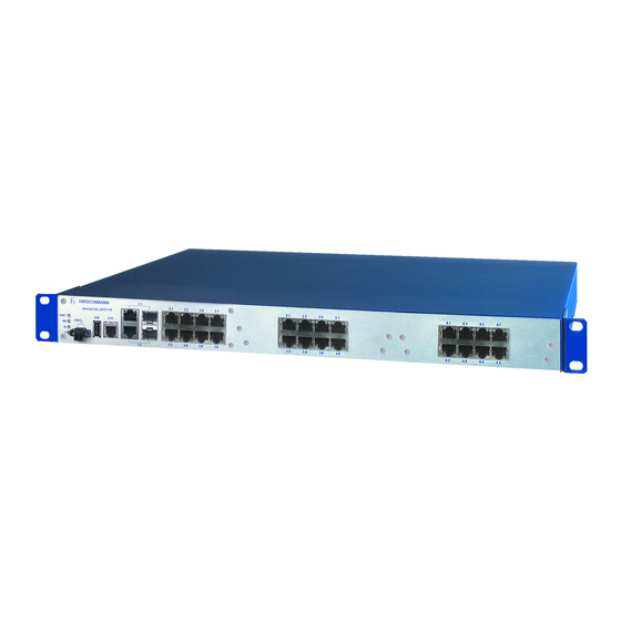
- Page 1 User Manual Installation Industrial ETHERNET Workgroup Switch MACH102 Family MACH102-8TP-F MACH102-24TP-F MACH102-8TP + M1-8TP-RJ45 + M1-8MM-SXC MACH102-8TP + M1-8SM-SXC + M1-8SFP Installation MACH102 Technical support Release 07 12/2020 https://hirschmann-support.belden.com...
- Page 2 The naming of copyrighted trademarks in this manual, even when not specially indicated, should not be taken to mean that these names may be considered as free in the sense of the trademark and tradename protection law and hence that they may be freely used by anyone. ©...
-
Page 3: Table Of Contents
Contents Important information Safety instructions About this manual Description General device description Description of the device variants 1.2.1 MACH102 basic devices 1.2.2 MACH102 media modules 1.2.3 SFP modules USB interface V.24 interface (external management) Assembly and start-up Installing the device 2.1.1 Checking the package contents 2.1.2 Installing media modules 2.1.3 Installing an SFP transceiver (optional) - Page 4 Removing a media module Removing the device Monitoring the ambient air temperature Maintenance and service Technical data General technical data 7.1.1 Basic device 7.1.2 Media modules Power supply 7.2.1 Basic device 7.2.2 Media modules Signal contact Interfaces Climatic conditions during operation Climatic conditions during storage Dimension drawings EMC and immunity...
-
Page 5: Important Information
Important information Note: Read these instructions carefully, and familiarize yourself with the device before trying to install, operate, or maintain it. The following notes may appear throughout this documentation or on the device. These notes warn of potential hazards or call attention to information that clarifies or simplifies a procedure. - Page 6 NOTICE NOTE provides information about procedures that do not involve the risk of injury. Installation MACH102 Release 07 12/2020...
-
Page 7: Safety Instructions
Safety instructions WARNING UNCONTROLLED MACHINE ACTIONS To avoid uncontrolled machine actions caused by data loss, configure all the data transmission devices individually. Before you start any machine which is controlled via data transmission, be sure to complete the configuration of all data transmission devices. Failure to follow these instructions can result in death, serious injury, or equipment damage. - Page 8 Certified usage Use the product only for the application cases described in the Hirschmann product information, including this manual. Operate the product only according to the technical specifications. See “General technical data” on page 49. Connect to the product only components suitable for the requirements of the specific application case.
- Page 9 Requirements for connecting the supply voltage Device variant Prerequisites: All variants All of the following requirements are complied with: The supply voltage corresponds to the voltage specified on the type plate of the device. The power supply conforms to overvoltage category I or II. ...
- Page 10 ESD Guidelines Media modules are equipped with electrostatically sensitive components. These can be destroyed by the effect of an electric field or by charge equalization when touching the printed circuit board or the contacts, or their lifetime can be affected. Media modules are therefore delivered packed in a conductive ESD protection bag.
- Page 11 Installation site requirements Operate the device at the specified ambient temperature (temperature of the ambient air at a distance of 2 in (5 cm) from the device) and at the specified relative humidity exclusively. When you are selecting the installation location, make sure you observe the climatic threshold values specified in the technical data.
- Page 12 Connecting data cables Note the following general recommendations for data cable connections in environments with high electrical interference levels: Keep the length of the data cables as short as possible. Use optical data cables for the data transmission between the buildings.
- Page 13 CE marking The labeled devices comply with the regulations contained in the following European directive(s): 2014/30/EU (EMC) Directive of the European Parliament and of the Council on the harmonisation of the laws of the Member States relating to electromagnetic compatibility. 2011/65/EU and 2015/863/EU (RoHS) Directive of the European Parliament and of the Council on the restriction of the use of certain hazardous substances in electrical and electronic...
- Page 14 47 CFR § 2.1077 Compliance Information MACH102 MACH102-Module U.S. Contact Information Belden – St. Louis 1 N. Brentwood Blvd. 15th Floor St. Louis, Missouri 63105, United States Phone: 314.854.8000 This device complies with part 15 of the FCC Rules. Operation is subject...
-
Page 15: About This Manual
About this manual The “Installation” user manual contains a device description, safety instructions, a description of the display, and the other information that you need to install the device. Documentation mentioned in the “User Manual Installation” that is not supplied with your device as a printout can be found as PDF files for downloading on the Internet at: https://www.doc.hirschmann.com Installation MACH102... -
Page 16: Key
The symbols used in this manual have the following meanings: Listing Work step Subheading Installation MACH102 Release 07 12/2020... -
Page 17: Description
Description General device description The MACH102 devices are managed workgroup switches with up to 24 Fast Ethernet ports and 2 Gigabit Ethernet ports. They consist of a basic device – and depending on the device variant – up to 2 pluggable media modules. They allow you to construct switched industrial Ethernet networks that conform to the IEEE 802.3 and 802.3u standards using copper wires or optical fibers in a bus or ring topology. -
Page 18: Description Of The Device Variants
If desired and depending on the device variant, the power can be supplied redundantly. The basic device has the following mounting options: Horizontal mounting in a 19" rack Horizontal mounting on a flat surface Vertical mounting on a flat surface ... - Page 19 Modular MACH102 basic devices Note: The MACH102-8TP, and MACH102-8TP-R devices from the Industrial Ethernet family MACH102 are modular switches. The devices consist of a basic switch device and, depending on the device variant, pluggable media modules for additional ports. Up to 2 pluggable media modules each provide an additional 8 Fast Ethernet interfaces.
- Page 20 Gigabit ETHERNET Fast ETHERNET FE Fast ETHERNET FE ports 9 ... 24 GE ports 1, 2 ports 1 ... 8 2 slots for optional media modules (Combo ports) 100/1000 Mbit/s F/ 8 × Twisted pair TX, 8 × Twisted pair TX, RJ45, 10/100 Mbit/s or O, SFP slots RJ45, 10/100 Mbit/s 8 ×...
-
Page 21: Mach102 Media Modules
MACH102-24TP-F, MACH102-24TP-FR 2 × Gigabit ETHERNET Combo ports 24 × Fast ETHERNET ports MACH102-24TP-FR: Power supply is designed redundantly. 2.5 2.7 3.5 3.7 4.5 4.7 1.1 1.1 V.24 StandBy R1 R2 FAULT MACH 1000 1.2 1.2 2.2 2.4 2.6 2.8 3.2 3.4... - Page 22 The modules are can be used in Basic device MACH102-8TP Basic device MACH102-8TP-R The media modules are hot-plug-compatible. This means that you have the option to replace modules with modules of the same kind during operation. Note: If you are replacing media modules, for example removing a TX media module and plugging in an FX media module in its place, the MACH102 device performs a warm start.
- Page 23 Media module M1-8TP-RJ45 The media module M1-8TP-RJ45 has 8 × 10/100 Mbit ports for connecting end devices or network segments according to the standards IEEE 802.3 100BASE-TX / IEEE 802.3 10 BASE-T. These ports support autonegotiation and autopolarity. The ports are RJ45 sockets.
- Page 24 M1-8TP-RJ45 PoE Disconnect the PoE power supply before removing the module ! Vor Entfernen des Moduls PoE- Spannungsversorgung trennen ! U: 48VDC I: 6A r _ + Figure 7: Media module M1-8TP-RJ45 PoE Note: Only trained service personnel are authorized to plug the M1-8TP-RJ45 PoE media module into the basic device or remove from the basic device.
-
Page 25: Sfp Modules
Media module M1-8SFP The M1-8MM-SC media module has 8 FX ports for connecting end devices or network segments in compliance with the IEEE 802.3u 100BASE-FX Multimode/Singlemode/Longhaul standard. The optical ports are configured in 100 Mbit/s full duplex (FDX) and support FEFI. These ports are SFP slots and are designed for the M-FAST SFP-... -
Page 26: Interface (External Management)
V.24 interface (external management) A serial interface is provided on the RJ11 socket (V.24 interface) for the local connection of an external management station (VT100 terminal or PC with corresponding terminal emulation). This enables you to set up a connection to the Command Line Interface (CLI) and to the system monitor. -
Page 27: Assembly And Start-Up
Assembly and start-up The device was developed for practical application in a harsh industrial environment. On delivery, the device is ready for operation. The following procedure has been proven to be successful for the assembly of the device: “Checking the package contents” ... -
Page 28: Installing An Sfp Transceiver (Optional)
Figure 12: MACH102 device equipped with media modules 1 - media module 1 2 - media module 2 To attach a media module, first remove the 2 screws on the protective cover of the media module slot and remove the protective cover. ... -
Page 29: Signal Contact "Fault
2.1.4 Signal contact “FAULT” Figure 14: MACH102 device, front view 1 - Signal contact Connect the signal contact via a 2-pin terminal block with screw lock. The signal contact (“FAULT“, pin assignment of terminal block figure 15) is used to monitor the device function, and thus supports remote diagnostics. -
Page 30: Installing The Device And Grounding
Note: Observe the electrical threshold values for the signal contact (see on page 50 “Signal contact”). Note: Relevant for North America: The tightening torque of the terminal block screws is 3 lb in. (0.34 Nm). Mount the terminal block for the signal contact on the front of the device using the screw lock. - Page 31 For more information on sliding/mounting rails and how to install them, please contact your switch cabinet manufacturer. The devices are designed to be mounted in a 19" switch cabinet. Ensure adequate ventilation. If necessary, install an additional fan in the switch cabinet to prevent the device from overheating.
- Page 32 CAUTION OVERHEATING OF THE DEVICE When installing the device, make sure any ventilation slots remain free. Maintain a clearance of at least 3.94 in (10 cm). Failure to follow these instructions can result in injury or equipment damage. Note: When operating the device in an environment with strong vibrations, you have the option to additionally fasten the device to the switch cabinet using 2 holding brackets on the back of the device.
- Page 33 Mounting on the wall CAUTION OVERHEATING OF THE DEVICE When installing the device, make sure any ventilation slots remain free. Maintain a clearance of at least 3.94 in (10 cm). Failure to follow these instructions can result in injury or equipment damage.
-
Page 34: Supply Voltage
2.1.6 Supply voltage WARNING ELECTRIC SHOCK Connect only a supply voltage that corresponds to the type plate of your device. Failure to follow these instructions can result in death, serious injury, or equipment damage. The input voltage range of the MACH102 basic devices is designed as 100 V AC ... - Page 35 Figure 20: Connections of the MACH102-8TP-R, MACH102-8TP-FR and MACH102-24TP-FR at the rear side of the device 1 - MACH102-8TP-R, MACH102-8TP-FR or MACH102-24TP-FR device 2 - Redundant power supply 100 V AC ... 240 V AC 3 - Standard power supply 100 V AC ... 240 V AC Note: With non-redundant supply of the mains voltage, the device reports a power failure.
- Page 36 WARNING FIRE HAZARD Disconnect the PoE voltage supply before removing the M1-8TP-RJ45 PoE media module. Non-adherence to these instructions can lead to death, serious physical injury or material damage. The PoE power is supplied via the wire pairs transmitting the signal (phantom voltage).
-
Page 37: Operating The Device
Figure 21: Connecting the supply voltage via the 3-pin terminal block 1 - Fastening screw for functional earth 2 - Fastening screw for supply voltage: - 3 - Fastening screw for supply voltage: + 4 - Connection for functional earth 5 - Connection for supply voltage: - 6 - Connection for supply voltage: + Note: Relevant for North America:... - Page 38 Use shielded data cables for gigabit transmission via copper cables, for example SF/UTP cables according to ISO/IEC 11801. Exclusively use shielded data cables to meet EMC requirements according to EN 50121- 4 and marine applications. Connect the data cables according to your requirements. See “Description of the device variants”...
- Page 39 The PoE power is supplied via the wire pairs transmitting the signal (phantom voltage). The individual ports (joint PoE voltage) are not electrically insulated from each other. The pin assignment corresponds to MDI-X. Function PoE voltage Receive path Minus terminal Receive path Minus terminal Transmission path Plus terminal...
-
Page 40: Support Of Poe
This port supports: Full or half duplex mode Default setting: Full duplex Note: Verify that the LH ports are connected only with LH ports, SM ports only with SM ports, and MM ports only with MM ports. 1000 Mbit/s F/O port ... - Page 41 V.24 StandBy R1 R2 FAULT MACH 1000 Figure 23: MACH102 display elements 1 - Display elements for the device status 2 - Display elements for the port status 3 - Display elements for the port status, media module 1 4 - Display elements for the port status, media module 2 Device state ...
- Page 42 If the manual setting is active on the signal contact “FAULT”, then the error display is independent of the setting of the signal contact. Port status These LEDs display port-related information. LS - Data, Link Status (1 green/yellow LED or 1 green and 1 yellow LED) Not glowing No valid connection.
-
Page 43: Making Basic Settings
Making basic settings Note: 2 or more devices configured with the same IP address can cause unpredictable operation of your network. Install and maintain a process that assigns a unique IP address to every device in the network. The IP parameters must be entered when the device is installed for the first time. -
Page 44: First Login (Password Change)
Log on to the device again with your new password. Note: If you lost your password, then use the System Monitor to reset the password. For further information see: https://hirschmann-support.belden.com/en/kb/required-password-change- new-procedure-for-first-time-login Installation MACH102 Release 07 12/2020... -
Page 45: Disassembly
Disassembly Removing an SFP transceiver (optional) Figure 24: De-installing SFP transceivers: De-installation sequence Proceed as follows: Open the locking mechanism of the SFP transceiver (1). Pull the SFP transceiver out of the slot via the open locking mechanism (2). ... -
Page 46: Removing The Device
Removing the device WARNING ELECTRIC SHOCK Disconnect the grounding only after disconnecting all other cables. Failure to follow these instructions can result in death, serious injury, or equipment damage. Proceed as follows: Disconnect the data cables. Disable the supply voltage. ... -
Page 47: Monitoring The Ambient Air Temperature
Monitoring the ambient air temperature Operate the device below the specified maximum ambient air temperature exclusively. See “General technical data” on page 49. The ambient air temperature is the temperature of the air at a distance of 2 in (5 cm) from the device. It depends on the installation conditions of the device, for example the distance from other devices or other objects, and the output of neighboring devices. -
Page 48: Maintenance And Service
Maintenance and service When designing this device, Hirschmann largely avoided using high-wear parts. The parts subject to wear and tear are dimensioned to last longer than the lifetime of the product when it is operated normally. Operate this device according to the specifications. ... -
Page 49: Technical Data
Technical data General technical data 7.1.1 Basic device Dimensions See “Dimension drawings” on page 52. Weight MACH102-8TP 7.94 lb (3600 g) MACH102-8TP-R 8.49 lb (3850 g) MACH102-8TP-F 7.94 lb (3600 g) MACH102-8TP-FR 8.49 lb (3850 g) MACH102-24TP-F 8.49 lb (3850 g) MACH102-24TP-FR 9.05 lb (4100 g) Pollution degree... -
Page 50: Media Modules
7.2.2 Media modules M1-8TP-RJ45 PoE Rated voltage range Type 1 PD, SELV/ES1 48 V DC Voltage range including maximum 45 V DC ... 57 V DC tolerances Rated power 2.5 A Rated voltage range Type 2 PD, SELV/ES1 54 V DC Voltage range including maximum 51 V DC ... -
Page 51: Climatic Conditions During Operation
MACH102-24TP-F 2 × Combo ports (alternatively 100/1000-Mbit/s F/O slot or 10/100/ MACH102-24TP-FR 1000 Mbit/s RJ45 port) 24 × 10/100 Mbit/s twisted pair, RJ45 socket Media modules M1-8TP-RJ45 8 × 100 Mbit/s twisted pair, RJ45 socket M1-8TP-RJ45 PoE 8 × 100 Mbit/s twisted pair PoE, RJ45 socket M1-8MM-SC 8 ×... -
Page 52: Dimension Drawings
Dimension drawings 2.1 2.3 2.5 2.7 V.24 2.2 2.4 2.6 2.8 465,9 18.34 482,6 Installation MACH102 Release 07 12/2020... -
Page 53: Emc And Immunity
EMC and immunity EMC interference immunity EN 61000-4-2 Electrostatic discharge Contact discharge 6 kV Air discharge 8 kV EN 61000-4-3 Electromagnetic field 80 MHz ... 3000 MHz max. 20 V/m EN 61000-4-4 Fast transients (burst) - Power line 2 kV - Data line 4 kV EN 61000-4-5... -
Page 54: Network Range
Network range Note: The line lengths specified for the transceivers apply for the respective fiber data (fiber attenuation and Bandwidth Length Product (BLP)/ Dispersion). 7.9.1 10/100/1000 Mbit/s twisted pair port 10/100/1000 Mbit/s twisted pair port Length of a twisted pair segment max. -
Page 55: Gigabit Ethernet Sfp Transceiver
c. With ultra-low-loss optical fiber. 7.9.3 Gigabit Ethernet SFP transceiver Product code Mode Wave length Fiber System Example for F/O line Fiber attenuation BLP/dispersion attenuation length M-SFP-SX/LC... 850 nm 50/125 µm 0 dB ... 7.5 dB 0 mi ... 0.34 mi 3.0 dB/km 400 MHz×km (0 km ... - Page 56 Product code Mode Wave length Fiber System Example for F/O line Fiber attenuation BLP/dispersion attenuation length M-SFP-LH+/LC EEC LH 1550 nm 9/125 µm 13 dB ... 32 dB 38.52 mi ... 72.07 mi 0.25 dB/km 19 ps/(nm×km) (62 km ... 116 km) M-SFP-LH+/LC EEC LH 1550 nm 9/125 µm...
-
Page 57: Power Consumption/Power Output, Temperature Range And Order Numbers
7.10 Power consumption/power output, temperature range and order numbers MACH102 Family Description Basic devices MACH102-8TP Basic device MACH102 family with 2 × Gigabit Ethernet combo port, 8 × Fast Ethernet TX, 2 sockets for media modules for up to 16 additional ports MACH102-8TP-R Basic device MACH102 family with 2 ×... -
Page 58: Scope Of Delivery
MACH102 Family power power Operating Order Device/module consumpti output temperature number (ambient air temperature) M1-8TP-RJ45 PoE 1.2 W 4.1 Btu (IT)/h +32 °F ... +122 °F 942 028-001 - external PoE voltage: (0 °C ... +50 °C) No PD M1-8TP-RJ45 PoE 2 W + PDs 6.9 Btu (IT)/h +32 °F ... -
Page 59: Underlying Technical Standards
Name Order number HiVision Network Management software 943 471-100 Network management software Industrial HiVision 943 156-xxx ELWIKA 5012 PG7 connector 933 175-100 (5-pin M12 socket for power supply and signal contact) 3-pin terminal block Low Voltage Interlock (50 pcs.) 943 845-011 Fast ETHERNET SFP modules: M-FAST SFP-MM / LC 943 865-001... - Page 60 RFC 768 RFC 1769 SNTP RFC 783 TFTP RFC 1907 MIB2 RFC 791 RFC 1945 HTTP/1.0 RFC 792 ICMP RFC 2131 DHCP RFC 793 RFC 2132 DHCP Options RFC 826 RFC 2236 IGMPv2 RFC 951 BOOTP RFC 2239 MAU-MIB RFC 1112 IGMPv1 RFC 3411 SNMP Framework...
-
Page 61: A Further Support
A list of local telephone numbers and email addresses for technical support directly from Hirschmann is available at https:// hirschmann-support.belden.com. This site also includes a free of charge knowledge base and a software download section. Hirschmann Competence Center The Hirschmann Competence Center is ahead of its competitors on three counts with its complete range of innovative services: ...
Need help?
Do you have a question about the Hirschmann MACH102 Series and is the answer not in the manual?
Questions and answers