Table of Contents
Advertisement
Quick Links
Advertisement
Table of Contents

Related Manuals for Belden HIRSCHMANN IT MAMMUTHUS MTS2948X-6Q-A


Summary of Contents for Belden HIRSCHMANN IT MAMMUTHUS MTS2948X-6Q-A
- Page 1 User Manual Installation MAMMUTHUS CORE LAYER SWITCH – MTS2948X-6Q-A MAMMUTHUS POWER MODULE – MTM2900-PSU250 MAMMUTHUS FAN MODULE – MTM2900-FAN Installing MAMMUTHUS SWITCH Technical Support Published on 01 01/2020 https://hirschmann-it.support.belden.com...
- Page 2 The performance characteristics described herein shall be binding only upon the express consent of the parties at the time of signing the contract. This paper is produced by Belden within its capacity. Belden reserves the right to change the contents of this manual without prior notice. Belden does not guarantee the correctness or accuracy of the information in this manual.
-
Page 3: Table Of Contents
Contents Safety guidelines About the manual Figure 1 Description 1.1 General equipment description 1.2 Equipment name and product code 1.2.1 Basic device 1.2.2 Power module 1.2.3 Fan module 1.3 Equipment view 1.3.1 MTS2948X-6Q-A 1.3.2 Power module 1.3.3 Fan module 1.4 Power supply 1.5 Ethernet port 1.5.1 10 Gbit/s F/O port 1.5.2 40 Gbit/s F/O port... - Page 4 2.4 Install SFP transceiver (optional) 2.5 Operate equipment 2.6 Connect data cable 2.7 Fill in the Device Label 3 Make basic settings 4 Monitor ambient air temperature 5 Maintenance and repair 6 Remove 6.1 Remove power module 6.2 Remove fan module 6.3 Remove SFP transceiver 6.4 Remove device 7 Technical data...
-
Page 5: Safety Guidelines
Make sure there is no component to be repaired in the equipment. In case of any damage or failure to the equipment, switch off the power and return the equipment to Belden for inspection. Qualification requirements for operators Only qualified personnel are allowed to operate the equipment. - Page 6 Correct use Use the equipment only for the purposes specified in the catalog and technical instructions. Only external devices and components recommended and permitted by the manufacturer can be used to operate the equipment. The correct and safe operation of this product depends on the correct operation, storage, assembly and installation during transport, as well as careful operation and maintenance procedures.
- Page 7 Power cord diameter at the power supply voltage input shall be at least 1mm² (North America: AWG16). Supply with AC voltage: Power cord diameter at the power supply voltage input shall be at least 0.75 mm² (North America: AWG18). The cross section of the grounding conductor shall be the same as or larger than that of ...
- Page 8 Special conditions for safe use Install the basic equipment and modules in a suitable enclosure based on specific environmental conditions to provide at least IP54 protection according to the requirements of EN 60529. Take measures to prevent instantaneous interference from exceeding 140% of the rated voltage at the voltage input.
- Page 9 Equipment enclosure Only technicians authorized by the manufacturer are allowed to open the enclosure. Keep vents open to ensure good air circulation. Ensure a minimum of 3.94 inches (10 cm) of space in front of the enclosure vent. ...
- Page 10 EU directives: Hirschmann Automation and Control GmbH Stuttgarter Str. 45-51 72654 Neckartenzlingen Germany www.belden.com Warning! As Class A equipment, it may cause interference to the living area. In such case, the operator may need to take appropriate actions. Warning! When Ethernet cables are used in industrial environments, they must be shielded.
- Page 11 LED or Laser Component LED or Laser Component conformed to IEC 60825-1 (2014): Class 1 laser products Class 1 LED products FCC description: The equipment complies with Section 15 of FCC. The equipment shall be operated in line with the following two requirements: (1) the equipment causes no harmful interference;...
-
Page 12: About The Manual
About the manual This user manual about “Installation” contains equipment instructions, safety instructions, display instructions, and other information required for equipment installation. Installing MAMMUTHUS SWITCH Published on 01 01/2020... -
Page 13: Figure
Figure The symbols used in this manual have the following meanings: Item list Work step Subtitle Installing MAMMUTHUS SWITCH Published on 01 01/2020... -
Page 14: Description
Description General equipment description MTS2900 switch provides excellent port density and switching performance, with enhanced L2 / L3 feature set, which can support data center level network, and provides high flexibility configuration options and OpenFlow support. It can be used as a core switch, combined with MTS2600\MTS2700\MTS2800 to form a compact data network solution, or as a convergence switch, combined with MTS8003 to form a large network solution. - Page 15 Power module You may choose 1 or 2 power modules with the same input voltage: Power modules are provided as accessories. Please refer to “Order number” on Page 47. Fan module The rear panel of the switch provides 4 fan slots, equipped with standard 4 fan modules.
-
Page 16: Equipment Name And Product Code
Equipment name and product code The equipment name corresponds to the product code. 1.2.1 Basic device Order Product code Description number 942999824 MTS2948X-6Q-A 1U rack-mounted 10G core layer switch, 48 × 1/10G SFP + slot, 6 × 40G QSFP+ slot, 2 × modular PSU slot, 4 ×... -
Page 17: Equipment View
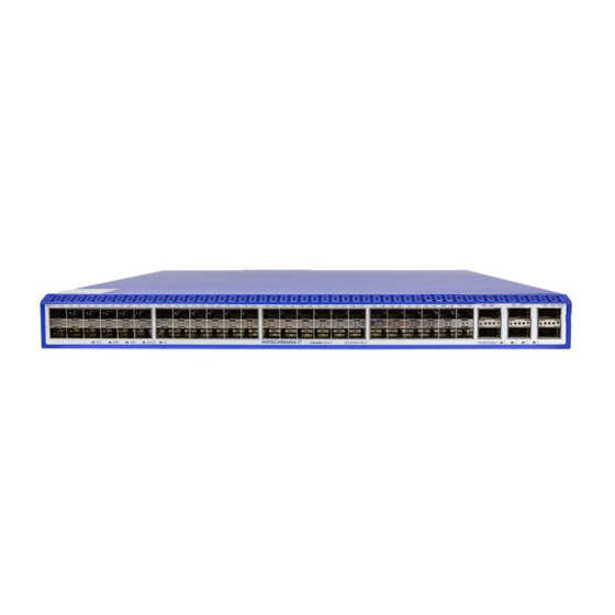
Equipment view 1.3.1 MTS2948X-6Q-A Front view Port Status LED (1 / 10G optical port) The equipment Status LEDs from left to right are as follows: SYS: System indicator PWR: Power indicator FAN: Fan indicator STACK: Stack indicator ID: ID indicator Port Status LED (40G optical port) BREAK OUT indicator 10 Gbit optical port (configurable to 1000Base-X) - Page 18 STACK: Stack indicator USB: USB indicator ID: ID indicator Reset button (press and hold for 5 seconds to restart the machine) Fan module slot (FAN1---FAN4) Modular power supply slot (PWR1, PWR2) Earthing terminal Installing MAMMUTHUS SWITCH Published on 01 01/2020...
-
Page 19: Power Module
1.3.2 Power module Installing MAMMUTHUS SWITCH Published on 01 01/2020... -
Page 20: Fan Module
1.3.3 Fan module Installing MAMMUTHUS SWITCH Published on 01 01/2020... -
Page 21: Power Supply
Power supply You may use the power module to supply voltage to the equipment: See the “Power module” on page 16 for information about connecting supply voltage. Installing MAMMUTHUS SWITCH Published on 01 01/2020... -
Page 22: Ethernet Port
Ethernet port You may use fiber optic (F/O) to connect terminal devices and other network segments to the equipment and the media module ports. 1.5.1 10 Gbit/s F/O port The port is an SFP + slot. The port allows you to connect network components according to IEEE 802.3. The port supports: Full duplex Delivery status... -
Page 23: Out-Of-Band Management Port
The port allows you to manage the equipment and upload configuration through the following protocols: SNMP SSH Telnet FTP See the “Command line interface user manual” for more information. You may download manual product page Hirschmann IT at https://Hirschmann-it.support.belden.com Installing MAMMUTHUS SWITCH Published on 01 01/2020... -
Page 24: Display Unit
Display unit After the power supply voltage is set, the software will start automatically and complete initialization. And then the equipment performs self-test. All LED indicators will come on in this process. 1.6.1 Equipment state These LEDs provide information about the conditions that affect the operation of the equipment. - Page 25 Indicator Indicator Indicator type Status name color Flashing: indicating stacking function is enabled, and the equipment is the main unit of the stacking system STACK indicator STACK Green ON: indicating stacking function is enabled, and the equipment is not the main unit of the stacking system OFF: indicating stacking function is not enabled Quick flashing (at frequency of 5Hz): used for site positioning, and for the operation and maintenance...
-
Page 26: Port Status
1.6.2 Port Status These LEDs provide port information. Indicator Indicator Indicator color Status type name Serial port RJ45 Flashing: indicating data sending in serial port indicator self-contained OFF: indicating no data sending in serial port yellow LED RJ45 build-in Flashing: indicating data receiving in serial port green LED OFF: indicating no data receiving in serial port 1000M... -
Page 27: Management Interface
Management interface 1.7.1 DC0 interface (external management) The serial interface is provided on RJ45 socket (DC0 interface), which can realize the local connection of external management station (VT100 terminal or PC with corresponding terminal simulation), and thus you are allowed to establish the connection to the command line interface CLI and the system monitor. -
Page 28: Installation
Installation These devices are developed for use in commercial environments. At the time of delivery, the equipment is ready for operation. Follow the following steps to install and configure the equipment: Unpack the box for inspection Install cover plate and power module (optional) ... -
Page 29: Install Equipment And Ground
Install equipment and ground You can install the equipment by the following options: Install the equipment in the switch cabinet Install the equipment on a vertical flat surface Warning Electric shock Such equipment can only be installed in switch cabinet or restricted operation place, and the equipment is accessible to maintenance personnel only. -
Page 30: Install Sfp Transceiver (Optional)
Follow the steps below: Install sliding or mounting rails in a 19 "switch cabinet as specified by the manufacturer. Place the equipment on the rail in the switch cabinet. Screw the mounting bracket to the switch cabinet to secure the equipment. - Page 31 Push the SFP transceiver into the slot until it is locked. Installing MAMMUTHUS SWITCH Published on 01 01/2020...
-
Page 32: Operate Equipment
Operate equipment Follow the steps below: Use screws to secure the connector to the equipment. You can refer to the specified tightening torque in the “General technical data” on page Enable the supply voltage. Connect data cable In environments with high electrical interference, note the following general recommendations for data cable connections: ... -
Page 33: Make Basic Settings
Make basic settings Note: Configuring two or more devices with the same IP address may lead to the network’s failure to function as expected. Install and maintain a program, to assign a unique IP address to each device in the network. IP parameters must be entered when the equipment is installed for the first time. -
Page 34: Monitor Ambient Air Temperature
Monitor ambient air temperature Please operate the equipment only below the specified maximum ambient air temperature. Please refer to “General technical data” on Page 38. The ambient air temperature is the air temperature at a distance of 2 inches (5 cm) from the equipment, specifically depending on the installation conditions of the equipment, for example, the distance of the equipment from other devices or other objects, and the output of adjacent equipment. -
Page 35: Maintenance And Repair
You may view the information and download software on the product page of Hirschmann IT at https://hirschmann-it.support.belden.com. Depending on the pollution level in the operating environment, regularly check whether the ventilation slot in the equipment is blocked. -
Page 36: Remove
Remove Remove power module Follow the steps below: Remove screws on the front panel of the power module. Pull the power module out of the slot. Seal the power module slot on the basic device with a cover plate. ... -
Page 37: Remove Sfp Transceiver
Remove SFP transceiver Follow the steps below: Unlock and pull the SFP transceiver out of the slot. Seal the SFP transceiver with a protective cover. Installing MAMMUTHUS SWITCH Published on 01 01/2020... -
Page 38: Remove Device
Remove device Warning Electric shock Please disconnect all other cables before disconnecting the ground wire. Failure to comply with these guidelines may result in death, serious injury or equipment damage. Follow the steps below: Disconnect the data cable. Disable the supply voltage. -
Page 39: Technical Data
Technical data General technical data Basic device Size Please refer to “Size diagram” on Page 40. Weight 10.8kg Power supply Rated voltage range 192 VAC ... 240 VAC ,50 Hz ... 60 Hz Maximum conductor AWG12 (2.5 mm2) diameter Equipment grounding Tighten torque 3.5~6.1 lb-in (0.4~0.7 Nm) - Page 40 Power module Size Please refer to “Size diagram” on Page 40. Weight MTM2900-PSU250 0.8Kg Installation Tighten torque 3.5~5.2 lb-in (0.4~0.6 Nm) power module Installation Tighten torque 3.5~5.2 lb-in (0.4~0.6 Nm) cover plate Power module Rated voltage range 192 VAC ... 240 VAC ,50 Hz ...
-
Page 41: Size Diagram
Size diagram Basic device Installing MAMMUTHUS SWITCH Published on 01 01/2020... - Page 42 Power module Installing MAMMUTHUS SWITCH Published on 01 01/2020...
- Page 43 Fan module Installing MAMMUTHUS SWITCH Published on 01 01/2020...
-
Page 44: Emc And Immunity
EMC and immunity EMC interference emission Standard application EN 55032 Class A DNV GL Guide — FCC 47 CFR Part 15 Class A EN 61000-6-4 Conformed EN 55032 AC/DC Power Line Class A DNV GL Guide AC/DC Power Line — FCC 47 CFR Part 15 AC/DC Power Line Class A... - Page 45 EMC immunity Standard application Electromagnetic field EN 61000-4-3 80 MHz ... 1000 MHz 10 V/m 1000 MHz ... 6000 MHz 3 V/m IEEE 1613 80 MHz ... 1000 MHz — Fast transient (burst) EN 61000-4-4 AC/DC Power Line ±2 kV IEEE C37.90.1 EN 61000-4-4 Data cable...
- Page 46 EMC immunity Standard application Damped vibration - AC/DC Power Line EN 61000-4-12 Cable / ground — IEEE C37.90.1 EN 61000-4-12 Cable / cable — IEEE C37.90.1 Damped oscillation - data cable EN 61000-4-12 Cable / ground — IEEE C37.90.1 EN 61000-4-12 Cable / cable —...
-
Page 47: Network Range
Network range Note: The line length specified for the transceiver applies to the corresponding fiber data (fiber attenuation and BLP/dispersion). Product code Mode Wave F/O cable length example Optical BLPc/disper MTS-SFP-10G-... length attenuatio sion -SR/LC... 850 nm 300 m (> 5.1 dB link budget at 3.0 dB/km 850nm ) -LR/LC... -
Page 48: Delivery Item, Order Number And Accessories
MTS-SFP-10G-ER/LC 942 999 853 MTS-SFP-10G-TX/RJ45 942 999 867 40G SFP module Order number MTS-SFP-40G-SR/LC 942999863 MTS-SFP-40G-LR/LC 942999864 a. You may access more information about certificates on the product page of Hirschmann IT https://hirschmann-it.support.belden.com Installing MAMMUTHUS SWITCH Published on 01 01/2020... -
Page 49: Basic Technical Standards
Basic technical standards Name FCC 47CFR Part 15 Code of Federal Regulations IEC 60825-1 Safety of Laser Products IEC/EN 61850-3 Communication networks and systems for power utility automation - Part 3: General requirements IEEE 1613 IEEE Environmental and Testing Requirements for Communications Networking Devices Installed in Electrical Power Substations IEEE 802.3 Ethernet... - Page 50 The equipment usually meets the technical standards set forth in the latest version. Only when the equipment shell has the certification mark, it means that the equipment is certified to a specific standard. Installing MAMMUTHUS SWITCH Published on 01 01/2020...
-
Page 51: A More Support
More support Technical issues If you have any technical question, please contact your local Hirschmann IT dealer or Belden directly. search partners’ addresses online https://hirschmann-it.support.belden.com. For the list of local telephone numbers and email addresses for you to get direct technical support from Hirschmann IT, please visit: https://hirschmann-it.support.belden.com. - Page 52 Installing MAMMUTHUS SWITCH Published on 01 01/2020...
Need help?
Do you have a question about the HIRSCHMANN IT MAMMUTHUS MTS2948X-6Q-A and is the answer not in the manual?
Questions and answers