
Subscribe to Our Youtube Channel
Related Manuals for Belden Hirschmann DRAGON MACH Series


Summary of Contents for Belden Hirschmann DRAGON MACH Series
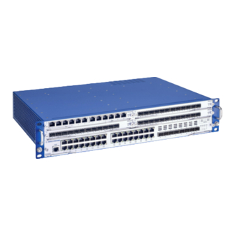
- Page 1 User Manual Installation Modular Industrial Gigabit Ethernet Backbone Switch DRAGON MACH Family Installation DRAGON MACH Family Technical support Release 04 02/2021 https://hirschmann-support.belden.com...
- Page 2 The naming of copyrighted trademarks in this manual, even when not specially indicated, should not be taken to mean that these names may be considered as free in the sense of the trademark and tradename protection law and hence that they may be freely used by anyone. ©...
-
Page 3: Table Of Contents
Contents Important information Safety instructions About this Manual Description General device description 1.1.1 Basic device 1.1.2 Media modules 1.1.3 Power supply unit module 1.1.4 Fan module Device views 1.2.1 Media modules 1.2.2 Power supply unit module 1.2.3 Fan module Power supply 1.3.1 Power supply modules 1.3.2 Media module D4K-10TP-PoE Signal contact... - Page 4 1.7.1 V.24 interface (external management) 1.7.2 USB interface 1.7.3 SD card interface Installation Checking the package contents Installing the SD card (optional) Installing a cover panel (optional) Installing a power supply module Installing a media module (optional) Mounting the fan module Installing and grounding the device Wiring and mounting the signal contact (optional) Connecting the supply voltage...
- Page 5 7.1.2 Power supply unit module 7.1.3 Fan module 7.1.4 Media modules Supply voltage 7.2.1 Power supply modules 7.2.2 Media module D4K-10TP-PoE Signal contact Power consumption/power output Climatic conditions during operation Climatic conditions during storage Dimension drawings 7.7.1 Basic device 7.7.2 Power supply unit module 7.7.3 Fan module 7.7.4 Media modules EMC and immunity...
- Page 6 Underlying technical standards Further support Installation DRAGON MACH Family Release 04 02/2021...
-
Page 7: Important Information
Important information Note: Read these instructions carefully, and familiarize yourself with the device before trying to install, operate, or maintain it. The following notes may appear throughout this documentation or on the device. These notes warn of potential hazards or call attention to information that clarifies or simplifies a procedure. - Page 8 NOTICE NOTE provides information about procedures that do not involve the risk of injury. Installation DRAGON MACH Family Release 04 02/2021...
-
Page 9: Safety Instructions
Safety instructions WARNING UNCONTROLLED MACHINE ACTIONS To avoid uncontrolled machine actions caused by data loss, configure all the data transmission devices individually. Before you start any machine which is controlled via data transmission, be sure to complete the configuration of all data transmission devices. Failure to follow these instructions can result in death, serious injury, or equipment damage. - Page 10 Installation site requirements Operate the device at the specified ambient temperature (temperature of the ambient air at a distance of 2 in (5 cm) from the device) and at the specified relative humidity exclusively. When you are selecting the installation location, make sure you observe the climatic threshold values specified in the technical data.
- Page 11 Device casing Only technicians authorized by the manufacturer are permitted to open the casing. Keep the ventilation slits free to ensure good air circulation. Make sure there is at least 3.94 in (10 cm) of space in front of the ventilation slits of the casing.
- Page 12 Grounding the device The device has 2 protective ground connections. The device is grounded via one of the two grounding nuts and in addition via the power supply connection (built-in non-heating device plug C14 according to IEC 60320-1). Ground the device before connecting any other cables. ...
- Page 13 Requirements for connecting the supply voltage Device variant Prerequisites: Basic device All of the following requirements are complied with: The supply voltage corresponds to the voltage specified on the type plate of the device. The power supply conforms to overvoltage category I or II. ...
- Page 14 CE marking The labeled devices comply with the regulations contained in the following European directive(s): 2011/65/EU and 2015/863/EU (RoHS) Directive of the European Parliament and of the Council on the restriction of the use of certain hazardous substances in electrical and electronic equipment.
- Page 15 DRAGON MACH4000 DRAGON MACH4500; D4K-AIR; D4K-PSU-300W-HV; D4K-12SFP; D4K-10TP-POE; D4K-12TP-RJ45 U.S. Contact Information Belden – St. Louis 1 N. Brentwood Blvd. 15th Floor St. Louis, Missouri 63105, United States Phone: 314.854.8000 This device complies with part 15 of the FCC Rules. Operation is subject...
-
Page 16: About This Manual
About this Manual The “Installation” user manual contains a device description, safety instructions, a description of the display, and the other information that you need to install the device. Documentation mentioned in the “User Manual Installation” that is not supplied with your device as a printout can be found as PDF files for downloading on the Internet at: https://www.doc.hirschmann.com Installation DRAGON MACH Family... -
Page 17: Key
The symbols used in this manual have the following meanings: Listing Work step Subheading Installation DRAGON MACH Family Release 04 02/2021... -
Page 18: Description
Certifications You have numerous options of combining the device characteristics. You can determine the possible combinations using the configurator which is available in the Belden Online Catalog https://catalog.belden.com on the web page of the device. Installation DRAGON MACH Family... -
Page 19: Media Modules
1.1.2 Media modules Figure 2: Media modules: Cover panel (1), D4K-12TP-RJ45 (2), D4K-12SFP (3), D4K-10TP-PoE (4) You have the option to supplement your basic device with up to 4 media modules. Each media module offers 12 additional Fast/Gigabit Ethernet ports or 10 Fast/Gigabit Ethernet ports with PoE. Seal unused slots with cover panels. -
Page 20: Fan Module
1.1.4 Fan module Figure 4: Fan module: D4K-AIR The basic device requires 1 fan module to dissipate heat. You obtain additional fan modules as accessories. See “Order numbers” on page 84. Installation DRAGON MACH Family Release 04 02/2021... -
Page 21: Device Views
Device views MACH4000 Front view Slot 1 Example: Media module D4K-12TP-RJ45 Slot 2 Example: Media module D4K-12SFP Slot 3 Example: Media module D4K-12TP-RJ45 Slot 4 Example: Cover panel for media module slot Mounting handle Screw with loss prevention Oblong hole LED display elements for device status Locking lever 4 ×... - Page 22 Rear view LED display elements for device status V.24 interface Connection for the signal contact PSU module Slot 1 Example: Cover panel for power supply module slot Screw with loss prevention Supply voltage connection PSU module Slot 2 Example: D4K-PSU-300W-HV LED display element PSU module status Slot for the SD card USB interface...
- Page 23 MACH4500 Front view Slot 1 Example: Media module D4K-12TP-RJ45 Slot 2 Example: Media module D4K-12SFP Slot 3 Example: Media module D4K-12TP-RJ45 Slot 4 Example: Cover panel for media module slot Mounting handle Screw with loss prevention Oblong hole LED display elements for device status Locking lever 8 ×...
-
Page 24: Media Modules
Rear view LED display elements for device status V.24 interface Connection for the signal contact PSU module Slot 1 Example: Cover panel for power supply module slot Screw with loss prevention Supply voltage connection PSU module Slot 2 Example: Power supply module D4K-PSU-300W-HV LED display element PSU module status Slot for the SD card USB interface... -
Page 25: Power Supply Unit Module
10 11 D4K-10TP-PoE 1 × 2-pin terminal block for the PoE supply voltage 2 ... 11 10 × RJ45 socket for 10/100/1000 Mbit/s PoE PD connections 1.2.2 Power supply unit module D4K-PSU-300W-HV LED display element PSU module status Safety catch for non-heating device cable connector (removable) Screw with loss prevention Built-in non-heating device plug (C14 plug according to IEC 60320-1) 1.2.3... -
Page 26: Power Supply
Power supply 1.3.1 Power supply modules You have the following options to supply your device with voltage: Figure 5: Power supply: PSU modules (rear side of device) Non-redundantly via 1 PSU module with built-in non-heating device plug (C14 plug according to IEC 60320-1) Installation DRAGON MACH Family Release 04 02/2021... - Page 27 Figure 6: Power supply: PSU modules (rear side of device) Redundantly via 2 PSU modules with built-in non-heating device plug (C14 plug according to IEC 60320-1) Installation DRAGON MACH Family Release 04 02/2021...
-
Page 28: Media Module D4K-10Tp-Poe
1.3.2 Media module D4K-10TP-PoE The media module D4K-10TP-PoE enables the supply of terminal devices with PoE voltage via twisted pair cable. To supply the module with PoE voltage you need an external power supply unit. Details about the power supply of the media module can be found in chapter “Supply voltage”... -
Page 29: Signal Contact
Signal contact 1 2 3 FAULT Figure 8: Signal contact: 3-pin terminal block with screw lock; position on the device (rear side of the device) Signal contact Normally closed contact Changeover contact Normally open contact The signal contact is a potential-free changeover contact. If the device is not connected to a power supply, the changeover contact (2) is connected to the normally closed contact (1) (see figure... -
Page 30: Ethernet Ports
Ethernet ports You can connect end devices and other segments to the device and media module ports using twisted pair cables or optical fibers (F/O). 1.5.1 10/100/1000 Mbit/s twisted pair port This port is an RJ45 socket. The 10/100/1000 Mbit/s twisted pair port allows you to connect network components according to the IEEE 802.3 10BASE-T/100BASE-TX/ 1000BASE-T standard. -
Page 31: 100/1000 Mbit/S F/O Port
1.5.2 100/1000 Mbit/s F/O port This port is an SFP slot. The 100/1000 Mbit/s F/O port allows you to connect network components according to the IEEE 802.3 100BASE-FX/1000BASE-SX/1000BASE-LX standard. This port supports: 1000 Mbit/s full duplex 100 Mbit/s half-duplex mode, 100 Mbit/s full duplex mode Delivery state: ... -
Page 32: Out-Of-Band Management Port
You will find more information here: See “Technical data” on page 69. Pin assignment RJ45 10/100 Mbit/s 1000 Mbit/s MDI-X mode BI_DB+ Positive V RX− BI_DB− Positive V BI_DA+ Negative V — BI_DD+ — — BI_DD− — TX− BI_DA− Negative V —... -
Page 33: Display Elements
Display elements After the supply voltage is set up, the Software starts and initializes the device. Afterwards, the device performs a self-test. During this process, various LEDs light up. 1.6.1 Device state These LEDs provide information about conditions which affect the operation of the whole device. - Page 34 LED Display Color Activity Meaning Ring Manager — none No redundancy configured green lights up Redundancy exists flashes 1 time a Device is reporting an incorrect period configuration of the RM function yellow lights up No redundancy exists FAN Fan module —...
- Page 35 FAN1 FAN2 STAT FAN3 FAN4 FAN5 Figure 11: Device status: Location of the display elements on the device (rear side of the device) LED Display Color Activity Meaning STAT Device Status — none Device is starting and/or is not ready for operation.
- Page 36 LED Display Color Activity Meaning Supply voltage — none Supply voltage is too low yellow lights up Supply voltage 1 or 2 is on flashes 4 times a Software update is running. Maintain the period power supply. green lights up Supply voltage 1 and 2 is on Supply voltage —...
-
Page 37: Psu Module Status
1.6.2 PSU module status Figure 12: PSU module status: Location of the display elements on the device (rear side of the device) LED Display Color Activity Meaning PWR Supply — none At least one of the following cases applies: voltage ... -
Page 38: Port Status
1.6.3 Port status These LEDs provide port-related information. 2 3 4 Figure 13: Port status: Location of the display elements on the device (front side of the device) Figure 14: Port status: location of the display elements on the device (front side of the device) Note: In the present hardware version, the lower port LEDs of the RJ45 ports are without function (N/A). -
Page 39: Management Interface Status
LED Display Color Activity Meaning L/D Link state/ — none Device detects an invalid or missing link data traffic green lights up Device detects a valid link flashes 1 time a period Port is switched to stand-by flashes 3 times a period Port is switched off yellow lights up Device detects a non-supported SFP transceiver or a non-supported data rate... -
Page 40: Media Module Status
1.6.5 Media module status D4K-12TP-RJ45 9 10 Figure 16: Media module status: Location of the display elements on the module Note: In the present hardware version, the right side port LED of each RJ45 port is without function (N/A). The port status is displayed via the left side port LED. - Page 41 D4K-12SFP 1 2 3 4 5 6 7 8 9 10 Figure 17: Media module status: Location of the display elements on the module LED Display Color Activity Meaning PWR Supply — none Media module is inoperative voltage green lights up Voltage supply to the media module is on Link state/ —...
- Page 42 D4K-10TP-PoE Figure 18: Media module status: Location of the display elements on the module LED Display Color Activity Meaning PWR Supply — none Media module is inoperative voltage green lights up Voltage supply to the media module is on The external supply voltage for PoE is connected yellow lights up...
-
Page 43: Management Interfaces
Management interfaces 1.7.1 V.24 interface (external management) V.24 Figure 19: V.24 interface: Location on the device (rear side of the device) A serial interface is provided on the RJ45 socket (V.24 interface) for the local connection of an external management station (VT100 terminal or PC with corresponding terminal emulation). -
Page 44: Usb Interface
1.7.2 USB interface V.24 Figure 20: USB interface: Location on the device (rear side of the device) The USB interface allows you to connect the AutoConfiguration Adapter ACA22 storage medium. This is used for saving/loading the configuration data and diagnostic information, and for loading the software. See “Accessories”... -
Page 45: Sd Card Interface
1.7.3 SD card interface Prerequisite: Only use Hirschmann SD cards. See “Accessories” on page 85. Figure 21: SD card interface: Location on the device (rear side of the device) The SD card interface allows you to connect the AutoConfiguration Adapter ACA31 storage medium. -
Page 46: Installation
Installation The devices have been developed for practical application in a harsh industrial environment. On delivery, the device is ready for operation. Perform the following steps to install and configure the device: Checking the package contents Installing the SD card (optional) ... -
Page 47: Installing The Sd Card (Optional)
Installing the SD card (optional) Prerequisite: Only use the AutoConfiguration Adapter ACA31 storage medium. See “Accessories” on page 85. Figure 22: Inserting an SD card: Location on the device (rear side of the device) Proceed as follows: Deactivate the write protection on the SD card by pushing the write- protect lock towards the middle of the card. -
Page 48: Installing A Cover Panel (Optional)
Figure 23: Inserting an SD card: Opening the SD card slot cover (rear side of the device) Proceed as follows: Push the SD card into the slot with the beveled corner on the right side. Slide the cover counterclockwise back into its original location using the unscrewed screw. -
Page 49: Installing A Power Supply Module
Installing a power supply module Hirschmann supplies the power supply modules in a ready-to-operate state. The power supply modules are hot-swappable. Figure 24: Mounting a PSU module: Installation (rear side of the device) Proceed as follows: Remove the cover panel (if mounted) from the power supply module slot on the device (1). -
Page 50: Installing A Media Module (Optional)
Installing a media module (optional) Hirschmann supplies the media modules in a ready-to-operate state. By using a media module, you obtain up to 12 additional Fast and/or Gigabit Ethernet ports. Figure 25: Mounting a media module: Installation sequence (front side of the device) Proceed as follows: ... -
Page 51: Mounting The Fan Module
Figure 26: Mounting a media module: Installation (front side of the device) Mounting the fan module CAUTION RISK OF INJURY FROM SPINNING FANS After removing the fan module during active operation, the individual fans continue to spin for a few seconds. Do not touch rotating fan blades. Do not insert objects into rotating fan blades. -
Page 52: Installing And Grounding The Device
Figure 27: Mounting a fan module: Installation (rear side of the device) Proceed as follows: Unscrew the 2 screws of the fan module on the device. Pull the fan module out of the slot using the foldable mounting handle. ... - Page 53 CAUTION OVERHEATING OF THE DEVICE Verify that all ventilation slots are clear when installing the device. Avoid touching the device while it is operating. Failure to follow these instructions can result in minor injury or equipment damage. Prerequisites: Install the device in the 19" switch cabinet using sliding or mounting rails.
-
Page 54: Wiring And Mounting The Signal Contact (Optional)
The device is grounded via one of the two grounding nuts and in addition via the power supply connection (built-in non-heating device plug C14 according to IEC 60320-1). Proceed as follows: Ground the device via one grounding nut. You find the prescribed tightening torque in chapter: “General data”... - Page 55 1 2 3 FAULT Signal contact Normally closed contact Changeover contact Normally open contact Proceed as follows: Connect the signal contact lines with the terminal block connections. Fasten the wires in the terminal block by tightening the terminal screws. ...
-
Page 56: Connecting The Supply Voltage
Connecting the supply voltage WARNING ELECTRIC SHOCK Start connecting electrical wires only if all safety requirements listed in chapter “General safety instructions” are fulfilled. Failure to follow these instructions can result in death, serious injury, or equipment damage. WARNING ELECTRIC SHOCK Never insert pointed objects (narrow screwdrivers, wires, etc.) into the device or into the connection terminals for electric conductors. - Page 57 Figure 30: Connecting the power supply: PSU modules (rear side of device) For every supply voltage to be connected, perform the following steps: On the rear side of the device, plug a non-heating device cable with C13 coupling according to IEC 60320-1 into the power supply connection (built-in C14 plug) of the PSU module.
-
Page 58: Media Module D4K-10Tp-Poe
2.9.2 Media module D4K-10TP-PoE Details about the power supply of the media module can be found in chapter “Supply voltage” on page 54 V DC / 8.4 A Figure 31: Power supply: Terminal block on the media module To supply the media module D4K-10TP-PoE with PoE voltage, proceed as follows: ... -
Page 59: Installing An Sfp Transceiver (Optional)
2.10 Installing an SFP transceiver (optional) Prerequisites: Exclusively use Hirschmann SFP transceivers. See “Accessories” on page 85. Figure 32: Installing SFP transceivers: Installation sequence Proceed as follows: Take the SFP transceiver out of the transport packaging (1). Remove the protection cap from the SFP transceiver (2). ... -
Page 60: Connecting Data Cables
2.12 Connecting data cables Note the following general recommendations for data cable connections in environments with high electrical interference levels: Keep the length of the data cables as short as possible. Use optical data cables for the data transmission between the buildings. ... -
Page 61: Making Basic Settings
Making basic settings Note: 2 or more devices configured with the same IP address can cause unpredictable operation of your network. Install and maintain a process that assigns a unique IP address to every device in the network. The IP parameters must be entered when the device is installed for the first time. - Page 62 Log on to the device again with your new password. Note: If you lost your password, then use the System Monitor to reset the password. For further information see: https://hirschmann-support.belden.com/en/kb/required-password- change-new-procedure-for-first-time-login Installation DRAGON MACH Family Release 04 02/2021...
-
Page 63: Monitoring The Ambient Air Temperature
Monitoring the ambient air temperature Operate the device below the specified maximum ambient air temperature exclusively. See “Climatic conditions during operation” on page 72. The ambient air temperature is the temperature of the air at a distance of 2 in (5 cm) from the device. -
Page 64: Maintenance And Service
Maintenance and service When designing this device, Hirschmann largely avoided using high-wear parts. The parts subject to wear and tear are dimensioned to last longer than the lifetime of the product when it is operated normally. Operate this device according to the specifications. ... -
Page 65: Disassembly
Disassembly De-installing a power supply module Figure 33: Removing a PSU module: Disassembly (rear side of the device) Proceed as follows: Remove the screws on the front panel of the power supply module (1). Pull the power supply module out of the slot (2). ... -
Page 66: Removing A Fan Module
Fasten the cover panel using the 2 screws on the basic device. You find the prescribed tightening torque in chapter: “General data” on page 69 Removing a fan module Figure 34: Removing a fan module: Disassembly (rear side of the device) Proceed as follows: ... -
Page 67: Removing A Media Module
Removing a media module Figure 35: Removing a media module: Removal sequence (front side of the device) Proceed as follows: Loosen the screws in the front panel of the media module. Open the locking mechanism of the media module by pressing the locking levers outwards (1). -
Page 68: Removing An Sfp Transceiver (Optional)
Removing an SFP transceiver (optional) Figure 37: De-installing SFP transceivers: De-installation sequence Proceed as follows: Open the locking mechanism of the SFP transceiver (1). Pull the SFP transceiver out of the slot via the open locking mechanism (2). ... -
Page 69: Technical Data
Technical data General data 7.1.1 Basic device Dimensions See “Dimension drawings” on page 73. Weight MACH4000 16.09 lb (7.3 kg) MACH4500 17.2 lb (7.8 kg) Power supply See “Power supply unit module” on page 74. Grounding the device Tightening torque 4.4 lb-in (0.5 Nm) Protective grounding Pollution degree... -
Page 70: Supply Voltage
Supply voltage 7.2.1 Power supply modules Rated voltage 100 V AC ... 240 V AC, 50 Hz ... 60 Hz Voltage range incl. maximum 90 V AC ... 264 V AC, 47 Hz ... 63 Hz tolerances Connection type Built-in non-heating device plug (C14 plug according to IEC 60320-1) min. -
Page 71: Signal Contact
Signal contact Connection type 3-pin terminal block Tightening torque 4.4 lb-in (0.5 Nm) min. conductor diameter AWG18 (0.75 mm²) max. conductor diameter AWG16 (1.3 mm²) Nominal value = 2 A at U = 230 V AC = 2 A at U = 30 V DC Power consumption/power output Name... -
Page 72: Climatic Conditions During Operation
Climatic conditions during operation Climatic conditions during operation Minimum clearance around the device Top and bottom sides of device: 2 in (5 cm) Left and right device side: 0.79 in (2 cm) Ambient air temperature +32 °F ... +140 °F (0 °C ... +60 °C) Humidity 10 % ... -
Page 73: Dimension Drawings
Dimension drawings 7.7.1 Basic device 18.98 25.39 17.52 0.12 0.39 Figure 38: Dimension drawings: basic device Installation DRAGON MACH Family Release 04 02/2021... -
Page 74: Power Supply Unit Module
7.7.2 Power supply unit module 10.91 9.84 Figure 39: Dimension drawings: power supply unit module 7.7.3 Fan module 2.17 Figure 40: Dimension drawings: fan module Installation DRAGON MACH Family Release 04 02/2021... -
Page 75: Media Modules
7.7.4 Media modules 8.66 Figure 41: Dimension drawings: media modules Installation DRAGON MACH Family Release 04 02/2021... -
Page 76: Emc And Immunity
EMC and immunity EMC interference emission Standard applications Railway applications (trackside) EN 55032 Class A Fulfilled Fulfilled FCC 47 CFR Part 15 Class A Fulfilled Fulfilled EN 61000-6-4 Fulfilled Fulfilled EMC interference immunity Standard applications Railway applications (trackside) Electrostatic discharge EN 61000-4-2 Contact discharge ±4 kV... -
Page 77: Network Range
Network range Note: The line lengths specified for the transceivers apply for the respective fiber data (fiber attenuation and Bandwidth Length Product (BLP)/ Dispersion). 7.9.1 10/100/1000 Mbit/s twisted pair port 10/100/1000 Mbit/s twisted pair port Length of a twisted pair segment max. -
Page 78: Bidirectional Fast Ethernet Sfp Transceiver
Product code Mode Wave length Fiber System Example for F/O line Fiber BLP/Dispersion attenuation length attenuation SFP-FAST-MM/LC EEC 1310 nm 62.5/125 µm 0 dB ... 11 dB 0 mi ... 2.49 mi 1.0 dB/km 500 MHz×km (0 km ... 4 km) SFP-FAST-SM/LC 1310 nm 9/125 µm... -
Page 79: Gigabit Ethernet Sfp Transceiver
7.9.4 Gigabit Ethernet SFP transceiver Product code Mode Wave length Fiber System Example for F/O line Fiber attenuation BLP/Dispersion attenuation length M-SFP-SX/LC... 850 nm 50/125 µm 0 dB ... 7.5 dB 0 mi ... 0.34 mi 3.0 dB/km 400 MHz×km (0 km ... -
Page 80: Bidirectional Gigabit Ethernet Sfp Transceiver
Product code Mode Wave length Fiber System Example for F/O line Fiber attenuation BLP/Dispersion attenuation length SFP-GIG-LX/LC... 1310 nm 50/125 µm 0 dB ... 10.5 dB 0 mi ... 0.34 mi 1.0 dB/km 800 MHz×km (0 km ... 0.55 km) SFP-GIG-LX/LC... -
Page 81: Gigabit Ethernet Sfp Transceiver
Product code Mode Wave length Wave length Fiber System Example for F/O line Fiber BLP/Dispersion attenuation length attenuation SFP-GIG-BB LX/ 1550 nm 1310 nm 9/125 µm 0 dB ... 15 dB 0 km ... 12.43 mi 0.25 dB/km 19 ps/(nm×km) LC EEC (0 km ... -
Page 82: 10 Gigabit Ethernet Sfp+ Transceiver
Product code Mode Wave length Fiber System Example for F/O Fiber BLP/Dispersion attenuation line length attenuation M-SFP-2.5-SM+/LC EEC SM 1310 nm 9/125 µm 12 dB ... 25 dB 27.96 mi (45 km) 0.4 dB/km 3.5 ps/(nm×km) M-SFP-2.5-LH/LC 1551 nm 9/125 µm 14 dB ... -
Page 83: Scope Of Delivery
Scope of delivery Basic device Amount Article 1 × Device 1 × Safety and general information sheet 1 × 3-pin terminal block for signal contact 1 × Fan module D4K-AIR 4 × Cover panel for media module slot 1 × Cover panel for power supply module slot Media modules Amount Article... -
Page 84: Order Numbers
Order numbers DRAGON MACH4000-48G+4X-L2A 942 154-001 DRAGON MACH4000-48G+4X-L3A-UR 942 154-002 DRAGON MACH4000-48G+4X-L3A-MR 942 154-003 DRAGON MACH4500-80G+8X-L2A 942 153-001 DRAGON MACH4500-80G+8X-L3A-UR 942 153-002 DRAGON MACH4500-80G+8X-L3A-MR 942 153-003 Fan module D4K-AIR 942 157-001 Power supply unit (PSU) D4K-PSU-300W-HV 942 156-001 Media module D4K-12TP-RJ45 942 155-001 Media module D4K-10TP-PoE 942 294-001... -
Page 85: 10 Accessories
10 Accessories Note that products recommended as accessories may have different characteristics to those of the device, which may limit the application range of the overall system. For example, if you add an accessory with IP20 to a device with IP65, the degree of protection of the overall system is reduced to IP20. - Page 86 Gigabit Ethernet SFP transceiver Order number M-SFP-TX/RJ45 943 977-001 M-SFP-SX/LC 943 014-001 M-SFP-SX/LC EEC 943 896-001 M-SFP-MX/LC EEC 942 108-001 M-SFP-LX/LC 943 015-001 M-SFP-LX/LC EEC 943 897-001 M-SFP-LX+/LC 942 023-001 M-SFP-LX+/ LC EEC 942 024-001 M-SFP-LH/LC 943 042-001 M-SFP-LH/LC EEC 943 898-001 M-SFP-LH+/LC 943 049-001...
- Page 87 10 Gigabit Ethernet SFP transceiver Order number (only applies to the basic device) M-SFP-10-ER/LC-EEC 942 212-001 M-SFP-10-ZR/LC 942 213-001 SFP-10-DAC-05m 942 280-001 SFP-10-DAC-1m 942 280-002 SFP-10-DAC-2m 942 280-003 SFP-10-DAC-4m 942 280-004 Other accessories Order number AutoConfiguration Adapter ACA22-USB (EEC) 942 124-001 AutoConfiguration Adapter ACA31 942 074-001 Terminal cable: RJ45 on Sub-D, 9-pin...
- Page 88 11 Underlying technical standards Name FCC 47 CFR Part 15 Code of Federal Regulations IEC 60825-1 Laser product safety IEEE 802.3 Ethernet EN 50121-4 Railway applications – EMC – Emission and immunity of the signaling and telecommunications apparatus (Rail Trackside) EN 55032 Electromagnetic compatibility of multimedia equipment –...
- Page 89 A list of local telephone numbers and email addresses for technical support directly from Hirschmann is available at https:// hirschmann-support.belden.com. This site also includes a free of charge knowledge base and a software download section. Hirschmann Competence Center The Hirschmann Competence Center is ahead of its competitors on three counts with its complete range of innovative services: ...
Need help?
Do you have a question about the Hirschmann DRAGON MACH Series and is the answer not in the manual?
Questions and answers