Table of Contents
Advertisement
Quick Links
User Manual
Installation
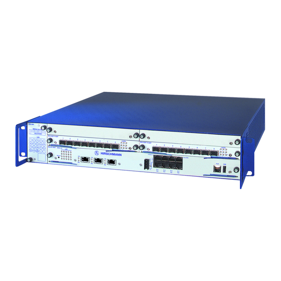
Modular Industrial Ethernet Backbone Switch
MACH4002 family
M4-AIR
M4-FAST 8SFP
1
2
3
MEDIA SLOTS
3
4
1
2
SLOT.PORT
LS
1
DA
LS
2
DA
LS
3
DA LS
M4-8TP-RJ45
LED
P
P1
P2
P3
P4
RM
RL1
RL2
FAN
RUN
MACH 4002 48+4G
LED
L/D
FDX 1000
AN TP/FO
RING
LED
PORT STBY
2
1
TEST
SELECT
LS
5.1
MACH 4002-48+4G
M4-AIR
M4-FAST 8SFP
1
2
3
MEDIA SLOTS
3
4
1
2
SLOT.PORT
1
2
3
LS
DA
LS
DA
LS
DA LS
M4-8TP-RJ45
LED
P
P1
P2
P3
P4
RM
RL1
RL2
FAN
RUN
MACH 4002 48+4G
LED
L/D
FDX 1000
AN TP/FO
RING
LED
PORT STBY
2
1
TEST
SELECT
6.1
MACH 4002-24G
M4-AIR
M4-FAST 8SFP
1
2
3
MEDIA SLOTS
3
4
1
2
SLOT.PORT
1
2
3
LS
DA
LS
DA
LS
DA LS
M4-8TP-RJ45
LED
P
P1
P2
P3
P4
RM
RL1
RL2
FAN
RUN
MACH 4002 48+4G
LED
L/D
FDX 1000
AN TP/FO
RING
LED
PORT STBY
2
1
TEST
SELECT
6.1
MACH 4002-48G
M4-AIR
M4-FAST 8SFP
1
2
3
MEDIA SLOTS
3
4
1
2
SLOT.PORT
1
2
3
LS
DA
LS
DA
LS
DA LS
M4-8TP-RJ45
LED
P
P1
P2
P3
P4
RM
RL1
RL2
FAN
RUN
MACH 4002 48+4G
LED
L/D
FDX 1000
AN TP/FO
RING
LED
PORT STBY
2
1
TEST
SELECT
5.1
MACH 4002-24G+3X
M4-AIR
M4-FAST 8SFP
1
2
3
MEDIA SLOTS
3
4
1
2
SLOT.PORT
1
2
3
LS
DA
LS
DA
LS
DA LS
M4-8TP-RJ45
LED
P
P1
P2
P3
P4
RM
RL1
RL2
FAN
RUN
MACH 4002 48+4G
LED
L/D
FDX 1000
AN TP/FO
RING
LED
PORT STBY
2
1
TEST
SELECT
5.1
MACH 4002-48G+3X
Installation MACH4002
Release 15 10/2019
LS/DA
M4-FAST 8SFP
4
5
6
7
8
1
4
7
2
5
8
P
3
6
4
DA LS
5
DA LS
6
DA LS
7
DA LS
8
DA
M4-FAST 8TP-RJ45-PoE
P
LS/DA 6.1
DA
LS
DA
LS
DA
LS
DA
5.2
5.3
5.4
LS/DA
M4-FAST 8SFP
4
5
6
7
8
1
4
7
2
5
8
P
3
6
4
5
6
DA LS
7
DA LS
8
DA LS
DA LS
DA
M4-FAST 8TP-RJ45-PoE
P
LS/DA 6.1
6.2
6.3
6.4
6.5
6.6
6.7
6.8
LS/DA
M4-FAST 8SFP
4
5
6
7
8
1
4
7
2
5
8
P
3
6
4
5
6
DA LS
7
DA LS
8
DA LS
DA LS
DA
M4-FAST 8TP-RJ45-PoE
P
LS/DA 6.1
6.2
6.3
6.4
6.5
6.6
6.7
6.8
LS/DA
M4-FAST 8SFP
4
5
6
7
8
1
4
7
2
5
8
P
3
6
4
5
6
DA LS
7
DA LS
8
DA LS
DA LS
DA
M4-FAST 8TP-RJ45-PoE
P
LS/DA 6.1
5.2
5.3
LS/DA
M4-FAST 8SFP
4
5
6
7
8
1
4
7
2
5
8
P
3
6
4
5
6
DA LS
7
DA LS
8
DA LS
DA LS
DA
M4-FAST 8TP-RJ45-PoE
P
LS/DA 6.1
5.2
5.3
1
2
3
4
5
6
7
8
LS
1
DA
LS
2
DA
LS
3
DA LS
4
DA LS
5
DA LS
6
DA LS
7
DA LS
8
DA
6.16 LS/DA
V.24
RL1
RL2
6.1
6.3
6.5
6.7
6.9
6.11
6.13
6.15
6.2
6.4
6.6
6.8
6.10
6.12
6.14
6.16
1
2
3
4
5
6
7
8
LS
1
DA
LS
2
DA
LS
3
DA LS
4
DA LS
5
DA LS
6
DA LS
7
DA LS
8
DA
V.24
RL1
RL2
6.1
6.3
6.5
6.7
6.2
6.4
6.6
6.8
1
2
3
4
5
6
7
8
1
2
3
4
5
6
DA LS
7
DA LS
8
LS
DA
LS
DA
LS
DA LS
DA LS
DA LS
DA
6.16 LS/DA
V.24
RL1
RL2
6.1
6.3
6.5
6.7
6.9
6.11
6.13
6.15
6.2
6.4
6.6
6.8
6.10
6.12
6.14
6.16
1
2
3
4
5
6
7
8
1
2
3
4
5
6
DA LS
7
DA LS
8
LS
DA
LS
DA
LS
DA LS
DA LS
DA LS
DA
V.24
RL1
RL2
6.1
6.3
6.5
6.7
6.2
6.4
6.6
6.8
1
2
3
4
5
6
7
8
1
2
3
4
5
6
DA LS
7
DA LS
8
LS
DA
LS
DA
LS
DA LS
DA LS
DA LS
DA
6.16 LS/DA
V.24
RL1
RL2
6.1
6.3
6.5
6.7
6.9
6.11
6.13
6.15
6.2
6.4
6.6
6.8
6.10
6.12
6.14
6.16
LS/DA
1
4
7
2
5
8
P
3
6
R
USB
LS/DA
1
4
7
2
5
8
P
3
6
R
USB
LS/DA
1
4
7
2
5
8
P
3
6
R
USB
LS/DA
1
4
7
2
5
8
P
3
6
R
USB
LS/DA
1
4
7
2
5
8
P
3
6
R
USB
Technical support
https://hirschmann-support.belden.com
Advertisement
Table of Contents

Related Manuals for Belden HIRSCHMANN MACH4002-48+4G


Summary of Contents for Belden HIRSCHMANN MACH4002-48+4G
- Page 1 DA LS DA LS M4-8TP-RJ45 M4-FAST 8TP-RJ45-PoE MACH 4002 48+4G LS/DA 6.1 6.16 LS/DA FDX 1000 AN TP/FO V.24 RING PORT STBY TEST SELECT 6.11 6.13 6.15 6.10 6.12 6.14 6.16 MACH 4002-48G+3X Installation MACH4002 Technical support Release 15 10/2019 https://hirschmann-support.belden.com...
- Page 2 The naming of copyrighted trademarks in this manual, even when not specially indicated, should not be taken to mean that these names may be considered as free in the sense of the trademark and tradename protection law and hence that they may be freely used by anyone. ©...
-
Page 3: Table Of Contents
Contents Safety instructions About this manual Legend Description General device description MACH4002 Basic Device Supply voltage 1.3.1 Supply voltage on the back of the device 1.3.2 M4-POWER power unit chassis 1.4.1 M4-AIR plug-in fan 1.4.2 Monitoring temperature and fan Integrated basic board 1.5.1 Left area of basic board 1.5.2 Right area of basic board Signal contact... - Page 4 1.10.3 ACA auto configuration adapter Installation Unpacking and checking Installing the device and grounding 2.2.1 Selecting the assembly location 2.2.2 Mounting on a flat surface 2.2.3 Mounting in a switch cabinet 2.2.4 Grounding Mounting the power supply unit on the back of the MACH4002 device Mounting the power unit chassis,connecting with the MACH4002 device...
-
Page 5: Safety Instructions
Safety instructions Certified usage Only use the device for application cases that are described in the Hirschmann product information, including this manual. Only operate the device according to the technical specifications. Supply voltage For every supply voltage to be connected, make sure the following requirements are met: ... - Page 6 Shielded ground The shielded ground wire of the twisted pairs lines is connected to the front panel as a conductor. Beware of possible short circuits when connecting a cable section with conductive shield braiding. Housing Only technicians authorized by the manufacturer are permitted to open the housing.
- Page 7 The basic board must not be removed. Removing the basic board invalidates the guarantee. The chassis should be installed in the horizontal position. After the device is switched off, the fan blades continue rotating for a number of seconds. Do not reach into a rotating fan! ...
- Page 8 General safety instructions This device is operated by electricity. You must follow precisely the prescribed safety requirements for the voltage connections in this document. See “Supply voltage” on page 5. Non-observance of these safety instructions can cause material damage and/or injuries.
- Page 9 Make sure you adhere to the following protection measures for electrostatically endangered assemblies: Create electrical equipotential bonding between yourself and your environment, e.g. using a wristband, which you clamp to the basic device (knurled screw of an interface card). When the power supply cable is connected, the basic device is grounded via the power supply connection.
- Page 10 You will find more information on norms and standards here: “Underlying norms and standards” on page 64 Warning! This is a class A device. This device can cause interference in living areas, and in this case the operator may be required to take appropriate measures.
-
Page 11: About This Manual
About this manual The “Installation” user manual contains a device description, safety instructions, a description of the display, and the other information that you need to install the device. The following manuals are available as PDF files on the CD/DVD supplied: ... -
Page 12: Legend
Legend The symbols used in this manual have the following meanings: Listing Work step Subheading Installation MACH4002 Release 15 10/2019... -
Page 13: Description
Description General device description The modular, industry-compatible MACH4002 Gigabit Ethernet system is used as an industrial backbone system, and also in applications with high data volumes, such as Voice/Video over IP. The MACH4002 is a modular, industry-compatible Gigabit Ethernet system in a 19"... -
Page 14: Mach4002 Basic Device
The addition, to the MACH family of backbone switches, of the RS20/RS22/ RS30/RS32/RS40 switches of the Open Rail family and the MICE family, the BAT wireless transmission system, the EAGLE security system, and products for the LION control room, provides continuous communication across all levels of the company. - Page 15 Depending on the MACH4002 device variant, the device provides you with the following ports and slots for equipping it with media modules: LS/DA LS/DA M4-AIR M4-FAST 8SFP M4-FAST 8SFP MEDIA SLOTS SLOT.PORT DA LS DA LS DA LS DA LS M4-8TP-RJ45 DA LS DA LS...
- Page 16 LS/DA LS/DA M4-AIR M4-FAST 8SFP M4-FAST 8SFP MEDIA SLOTS SLOT.PORT DA LS DA LS DA LS DA LS DA LS DA LS DA LS DA LS DA LS DA LS M4-8TP-RJ45 M4-FAST 8TP-RJ45-PoE MACH 4002 48+4G LS/DA 6.1 6.16 LS/DA FDX 1000 AN TP/FO V.24...
- Page 17 The devices comply with the specifications of the standards: ISO/IEC 8802-3u 100BASE-TX/-1000BASE-TX ISO/IEC 8802-3 100BASE-FX ISO/IEC 8802-3 1000BASE-SX/LX ISO/IEC 8802-3 10GBASE-SR/LR The MACH4002 basic devices are 2 height modules high (approx. 88mm) and, depending on the device variant and the connected media, they provide you with ...
-
Page 18: Supply Voltage
Along with the 10-Gigabit (if present), Gigabit and Fast Ethernet ports, the front of the basic board also has the following connections: A USB socket for connecting an ACA21-USB AutoConfiguration Adapter A V.24 socket for the network management connection ... -
Page 19: Supply Voltage On The Back Of The Device
Figure 7: Back side of the MACH4002 basic device 1 - M4-POWER connection (voltage input P3-1/P3-2, external) 2 - M4-POWER connection (voltage input P4-1/P4-2, external) 3 - Slot for slide-in power supply unit (voltage input P1 and, if required, P2) With redundant supply, the power supply unit with the higher output voltage supplies the device on its own. -
Page 20: M4-Power Power Unit Chassis
M4-S-AC/DC 300W M4-S-48VDC 300W M4-S-24VDC 300W 1.3.2 M4-POWER power unit chassis Note: Consider the sequence for the cabling of the power unit chassis. See “Mounting the power unit chassis, connecting with the MACH4002 device” on page 43. The M4-POWER power unit chassis enables redundant power supply. It has three slots for plug-in power units. -
Page 21: Fan
Figure 10: M4-POWER power unit chassis, back side of the device Plug-in power units for M4-POWER power unit chassis M4-P-AC/DC 300W M4-P-24VDC 300W, 2 inputs for redundant power supply M4-P-48VDC 300W, 2 inputs for redundant power supply (see on page 61 “Order numbers/product description”). - Page 22 NOTE OVERHEATING OF THE DEVICE Depending on the ambient temperature, the device can be operated for a maximum of one to two minutes with the fan unit removed. Non-adherence to these instructions can lead to material damage. On the front of the MACH4002 chassis the M4-AIR or M4-AIR-L plug-in fan is located on the left.
-
Page 23: Monitoring Temperature And Fan
1.4.2 Monitoring temperature and fan Fan monitoring Every individual fan sends a speed-dependent signal to the basic system. The fan monitoring displays the failure of one or more individual fans. The effect of insufficient ventilation If the device is insufficiently ventilated by its fans, this either causes the assemblies to age faster (MTBF value) or triggers error statuses, and it usually leads to transmission errors on the Ethernet connections. -
Page 24: Integrated Basic Board
Integrated basic board Depending on the device variant, the integrated basic board provides you with different numbers and types of port. See “Order numbers/product description” on page 61. MACH 4002 48+4G LS/DA 6.1 6.16 LS/DA V.24 SELECT 6.11 6.13 6.15 6.10 6.12 6.14... - Page 25 If an SFP transceiver is mounted, the RJ45 socket is switched off. The LEDs each apply to the active port. You can use the SELECT button to test the TP or FO connections. See “Order numbers/product description” on page 61. Eight Gigabit Ethernet ports (Combo) ...
-
Page 26: Right Area Of Basic Board
1.5.2 Right area of basic board 16 Fast Ethernet ports in MACH4002-48+4G There are sixteen 10/100BASE-TX ports (ports number 6.1 to 6.16) for connecting network segments on the right side of the basic board. These ports are RJ45 sockets. 6.11 6.13 6.15... -
Page 27: Signal Contact
Signal contact MACH 4002 48G LS/DA 6.1 6.16 LS/DA V.24 SELECT 6.11 6.13 6.15 6.10 6.12 6.14 6.16 Figure 17: 4-pin signal contact The signal contact is a potential-free relay contact. The device allows you to perform remote diagnosis via the signal contact. In the process, the device signals events such as a line interruption. -
Page 28: M4-8Tp-Rj45
MACH4002 device M4-8TP-RJ45 M4-FAST 8TP-RJ45 M4-FAST 8-SFP M4-GIGA 8-SFP MACH4002-48+4G 0 - 4 0 - 4 0 - 4 Media modules Media modules Media modules Media modules MACH4002-24G... 0 - 2 0 - 2 0 - 2 0 - 2 Media modules Media modules Media modules... -
Page 29: M4-Giga 8-Sfp
LS/DA M4-FAST 8SFP The following Fast Ethernet SFP transceivers are available to you for the M4- FAST 8-SFP media module: Fast Ethernet SFP transceivers: – M-FAST SFP-MM/LC – M-FAST SFP-SM/LC – M-FAST SFP-SM/LC – M-FAST SFP-SM+/LC – M-FAST SFP-LH/LC See “Order numbers/product description”... -
Page 30: Sfp/Xfp Transceiver
SFP/XFP transceiver Figure 19: SFP transceiver and XFP transceiver 1 – Fast Ethernet F/O SFP transceiver 2 – Gigabit Ethernet F/O SFP transceiver 3 – 10-Gigabit Ethernet F/O XFP transceiver SFP is the acronym for Small Form-factor Pluggable which is also commonly known as mini-GBIC (GigaBit Interface Converter). -
Page 31: 100 Mbit/S F/O Connection
The socket housing is electrically connected to the front panel. The pin assignment corresponds to MDI-X. Figure Function Ports with PoE support: PoE voltage feed BI_DB+ Minus terminal of the supply voltage BI_DB− Minus terminal of the supply voltage BI_DA+ Plus terminal of the supply voltage BI_DD+ BI_DD−... -
Page 32: Poe Ports
Default setting: Full duplex Note: Make sure that you connect SR ports exclusively with SR ports, LR ports exclusively with LR ports, ER ports exclusively with ER ports, and ZR ports exclusively with ZR ports. 1.9.5 PoE ports The M4-FAST 8TP-RJ45 PoE media module supports Power over Ethernet (PoE) according to IEEE 802.3af. -
Page 33: Display Elements
When you are using an SFP transceiver, you get an optical interface. You thus deactivate the corresponding TP interface. 1.10 Display elements After the operating voltage is set up, the software starts and initializes itself. Afterwards, the device performs a self-test. During this process, various LEDs light up. -
Page 34: Port Status Display
Display Color Activity Meaning Power Green Lights up Supply voltage 4 is present at external input supply None No supply voltage 4, or voltage too low, at external input 4 Green flashing Supply voltage 4 is present, but the plug-in power unit is reporting an error. -
Page 35: Aca Auto Configuration Adapter
Display Color Activity Meaning Link status Green Lights up The port LEDs of the media modules display the connection status. Full duplex/ Green Lights up The port LEDs of the media modules display half duplex the half-duplex or full-duplex connection status. - Page 36 Port state LS/DA M4-FAST 8SFP DA LS DA LS DA LS DA LS DA LS M4-FAST 8TP-RJ45-PoE LS/DA 6.1 6.16 LS/DA V.24 6.11 6.13 6.15 6.10 6.12 6.14 6.16 These LEDs display port-related information. For each port, the following are available: ...
- Page 37 Display Color Activity Meaning 1 ... n Stand-by Green Lights up Connection port for the data line. Yellow Lights up Connection port for the control line. green/ flashing No stand-by partner available. yellow 1 ... n LED TEST Green Lights up The LED is not operating.
- Page 38 RJ11 RJ11 n.c. Figure 21: Pin assignment of the V.24 interface and the DB9 connector Note: You will find the order number for the terminal cable, which is ordered separately, in the Technical Data chapter (see on page 55 “Technical data”).
-
Page 39: Installation
Installation On delivery, the device is ready for operation. The following procedure has been proven to be successful for the assembly of the device: Unpacking and checking Installing the device and grounding Mounting the power supply unit on the back of the MACH4002 device ... -
Page 40: Mounting On A Flat Surface
Select the assembly location according to the safety guidelines (see on page 5 “Safety instructions”). When selecting the assembly location, also make sure the following requirements are met: The assembly location can be accessed for maintenance and repair work. ... - Page 41 Make sure there is sufficient ventilation. If necessary, provide a fan for the 19" switch cabinet. This will prevent the basic devices from overheating. Measure the depth of the 19" switch cabinet so as to allow the power supply cables to be fitted at the back and the data cables to be fitted at the front.
-
Page 42: Grounding
2.2.4 Grounding The device is grounded via the power supply connections. Note: The shielding ground of the connectable twisted pairs lines is connected to the front panel as a conductor. When the device is being operated via the 230/120 V AC power supply unit, it is grounded via the safety plug. -
Page 43: Mounting The Power Unit Chassis,Connecting With The Mach4002 Device
Mounting the power unit chassis, connecting with the MACH4002 device NOTE SHORT-CIRCUIT Insert the plugs of the power supply cables in straight in order to avoid the bridging of pins on the power supply connection of the MACH4002 device. Non-adherence to these instructions can lead to material damage. Note: The power supply cables between the M4-POWER power unit chassis and the MACH4002 device are not hot-swappable. -
Page 44: Installing The M4-Air
M4-S-AC/DC 300W M4-S-AC/DC 300W M4-POWER Figure 23: Redundant power supply via the M4-POWER power unit chassis. Step 1: Connect MACH4002 device(s) to M4-POWER 1 - MACH4002, back 2 - M4-POWER power unit chassis, back 3 - Not hot-swappable Figure 24: Redundant power supply via the M4-POWER power unit chassis. Step 2: Connecting M4-POWER to the power supply (example: configuration with 2 plug-in power units) 1 - Plug-in power unit 1... -
Page 45: Installing The Plug-In Power Units In The M4-Power Power Unit Chassis
Installing the plug-in power units in the M4-POWER power unit chassis When replacing a defective plug-in power unit, only use a plug-in power unit of the M4-P-... 300W type (see on page 61 “Order numbers/product description”) Remove the power supply cables. ... -
Page 46: Installing The Media Modules
Installing the media modules The switch has four inputs for connecting media modules. The number of connectable network segments depends on the number of media modules installed. If the full four media modules with 8 ports each are connected, then in addition to the ports of the basic board, you get a further 32 ports for connecting network segments. - Page 47 Insert the media module as far as it will go into the desired slot by closing the blue insertion catches. (See Fig. above, step 3). Screw the two knurled screws in the front panel of the media module flush with the frame of the basic device.
-
Page 48: Installing Sfp/Xfp Transceivers (Optional)
Installing SFP/XFP transceivers (optional) Note: You will find further information under “SFP/XFP transceiver” on page Note: Only use Hirschmann SFP/XFP transceivers. See “Accessories” on page 63. Figure 26: F/O SFP transceiver Before attaching an SFP or XFP transceiver, first remove the protective cap of the SFP/XFP transceiver. -
Page 49: Wiring And Assembling The Signal Contact
For the DC input of the DC plug-in power units at P1 and P2, use a nominal rating of not more than 20 A - slow-blow characteristic. Do not use a redundant power supply at P1 and P2 simultaneously if one of the “+”... -
Page 50: Connecting The Data Lines
The potential-free signal contact (relay contact, closed circuit) reports through a break in contact: The failure of at least one supply voltage. The device is not operational. The failure of the connection on at least one port. The report of the link status can be masked by the Management for each port. -
Page 51: Basic Set-Up
Basic set-up WARNING UNINTENTIONAL OPERATION IN DEVICE Install and maintain a process that assigns a unique IP address to every device in the network. Failure to follow these instructions can result in death, serious injury, or equipment damage. The IP parameters must be entered when the device is installed for the first time. -
Page 52: Maintenance And Service
Maintenance and service When designing this device, Hirschmann was largely able to forego using parts that are subject to wear and tear. The parts subject to wear are designed to last longer than the lifetime of the product when it is operated properly. -
Page 53: Deinstallation
Deinstallation Deinstalling the media modules Figure 28: Deinstalling the media modules 1 - Step 1 2 - Step 2 3 - Step 3 Note: Note the “ESD Guidelines” on page 8 and the “Safety instructions” on page Lever the selected media module from the slot by pulling the blue insertion catches (see Fig. -
Page 54: Deinstalling The M4-Air
Figure 29: Deinstalling an SFP transceiver Deinstalling the M4-AIR... plug-in fan unit CAUTION ROTATING PARTS After the device is switched off, the fan blades continue rotating for a number of seconds. Do not reach into a rotating fan! Failure to follow these instructions can result in injury or equipment damage. -
Page 55: Technical Data
Technical data General technical data Dimensions MACH4002-... W x H x D: 480 mm × 88 mm × 435 mm M4-POWER W x H x D: 480 mm × 88 mm × 435 mm Assembly MACH4002-... 19" switch cabinet M4-POWER 19"... - Page 56 Operating MACH4002-... With M4-AIR plug-in fan unit: temperature M4-S-xx, M4-P-xx Ambient air: 0 °C ... +60 °C M-SFP-xx/xx With M4-AIR-L plug-in fan unit: M-XFP-xx/xx Ambient air: 0 °C ... +40 °C M-FAST SFP-xx/xx M4-8TP-RJ45 M4-8TP-RJ45 PoE M4-FAST 8-SFP M4-GIGA 8-SFP Pollution degree Protection classes Laser protection Class 1 according to EN 60825-1 (2001)
- Page 57 Dimension drawings 482,6 19.00 inch 465,1 18.31 17.52 Figure 30: Dimensions Interfaces Interface Design MACH4002-... Signal contact 4-pin pluggable terminal block V.24 access 1 x RJ11 socket USB interface For connecting an AutoConfiguration Adapter ACA 21- Installation MACH4002 Release 15 10/2019...
- Page 58 EMC and immunity EMC interference immunity IEC/EN 61000-4-2 Electrostatic discharge Contact discharge 6 kV Air discharge 8 kV IEC/EN 61000-4-3 Electromagnetic field 80 - 2,700 MHz 10 V/m IEC/EN 61000-4-4 Fast transients (burst) - Power line 2 kV - Data line 4 kV IEC/EN 61000-4-5 Voltage surges...
- Page 59 Product Wave Fiber System Example Fiber data BLP/ code length attenuatio for F/O dispersion M-FAST- line length SFP-... -SM+/ SM 1310 nm 9/125 µm 10-29 dB 25-65 km 0.4 dB/km 3.5 ps/(nm×km) LC... -LH/LC... SM 1550 nm 9/125 µm 10-29 dB 47-104 km 0.25 dB/km 19 ps/(nm×km) Table 10: Fiber port 100BASE-FX (SFP fiber optic Fast Ethernet Transceiver) Product...
- Page 60 Product Wave Wave Fiber System Example Fiber BLP/ code length length attenuat for F/O data dispersion M-SFP- line BIDI... length Type A LX/ 1310 nm 1550 nm 9/125 µm 0-11 dB 0-20 km 0.4 dB/ 3.5 ps/(nm×km) LC EEC Type B LX/ 1550 nm 1310 nm 9/125 µm 0-11 dB 0-20 km 0.25 19 ps/(nm×km)
- Page 61 Name Maximum Maximum power power output consumption M4-8TP-RJ45 2.0 W 7.0 Btu (IT)/h M4-8TP-RJ45 PoE 15.0 W 52.0 Btu (IT)/h M4-FAST-SFP 15.0 W 52.0 Btu (IT)/h M4-GIGA-SFP 3.0 W 10.2 Btu (IT)/h Scope of delivery Device Scope of delivery MACH4002-...
- Page 62 Product description Description Order No. Switch chassis 24G+3X (up to 24 Gigabit Ethernet ports and three 10-Gigabit Ethernet ports) incl. plug-in fan unit without power supply unit MACH4002-24G+3X- - with Layer2 Professional software 943 915-101 MACH4002-24G+3X- - with Layer3 Enhanced software 943 915-201 MACH4002-24G+3X- - with Layer3 Professional software...
- Page 63 Accessories Note: Please note that products recommended as accessories may have characteristics that do not fully correspond to those of the corresponding product. This may limit their possible usage range in the overall system. Name Operating temperature Order number (chassis) AutoConfiguration Adapter ACA 21-USB 943 271-001...
- Page 64 Underlying norms and standards Standard EN 61000-6-2 Electromagnetic compatibility (EMC) – Part 6-2: Generic standards – Immunity for industrial environments EN 55032 Information technology equipment – Radio disturbance characteristics – Limits and methods of measurement EN 60950-1 Information technology equipment – Safety – Part 1: General requirements EN 61131-2 Programmable controllers –...
- Page 65 A list of local telephone numbers and email addresses for technical support directly from Hirschmann is available at https:// hirschmann-support.belden.com. This site also includes a free of charge knowledge base and a software download section. Hirschmann Competence Center The Hirschmann Competence Center is ahead of its competitors on three counts with its complete range of innovative services: ...
Need help?
Do you have a question about the HIRSCHMANN MACH4002-48+4G and is the answer not in the manual?
Questions and answers