Table of Contents
Advertisement
Quick Links
Advertisement
Table of Contents

Related Manuals for Robe iSpiider


Summary of Contents for Robe iSpiider
- Page 1 QR code for user manual Version 1.7...
-
Page 2: Table Of Contents
15.1 Torques for watertight covers ................41 15.2 Torques of Pan/Tilt motors screws ................. 45 15.3 Checking and replacing the silica gel desiccants ..........46 16. Robe Ethernet Access Portal (REAP) ............... 50 17. Technical Specifications .................... 58 18. Photometric diagrams....................61 19. -
Page 3: Safety Instructions
Please consider that damages caused by manual modifications to the device are not subject to warranty. The Robin iSpiider was designed for outdoor use and it is intended for professional application only. It is not for household use. -
Page 4: Operating Determination
Potential foggy front lens array does not influence function of the fixture and does not subject to complaint. Please use only an original ROBE packaging (paper box, loader case or foam shell) for transporting the device, otherwise potential damage of the device during its transport will not subject to warranty. - Page 5 including interference that may cause undesired operation. Changes or modifications not expressly approved by the party responsible for compliance could void the user's authority to operate the equipment. The [Device] wireless operation is safe and complies to RF Exposure requirements This equipment has been tested and found to comply with the limits for a Class B digital device, pursuant to part 15 of the FCC Rules.
-
Page 6: Fixture Exterior View
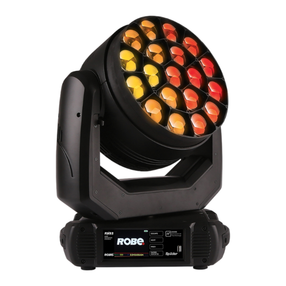
3. Fixture exterior view 1 - Lens array 2 - Yoke 3 - Handle 4 - Control panel 5 - Pan lock 6 - Tilt lock 7 - Power (Neutrik TrueOne) 8 - Base 9 - Cover of fuse holde 10 - Ethernet IN 11 - Ethernet OUT 12- 5-pin DMX IN... -
Page 7: Installation
The fixture has to be connected to an electric outlet which is equipped with a residual-current device (residual-current circuit breaker)! The Robin iSpiider is equipped with auto-switching power supply that automatically adjusts to any 50-60Hz AC power source from 100-240 Volts. -
Page 8: Rigging The Fixture
4.2 Rigging the fixture A structure intended for installation of the fixture (s) must safely hold weight of the fixture(s) placed on it. The structure has to be certificated to the purpose. The fixture (fixtures) must be installed in accordance with national and local electrical and construction codes and regulations. - Page 9 1-Mounting brackets Omega CL 2-Quick-lock fasteners 3-Safety wire 4-Clamps 5-Attachment point 6-Truss Available positions of Omega holders: Allowed installation positions of the iSpiider:...
- Page 10 Note for open-air installation: if the fixture stands on the ground, min. distance of 4" (10cm) between the fixture base and the ground has to be kept. When installing fixtures side-by-side, avoid illuminating one fixture with another! DANGER TO LIFE! Before taking into operation for the first time,the installation has to be approved by an expert! In order to protect the internal parts of the head from the sun, the function...
- Page 11 Signal (–) and Signal (+) into 5-pin XLR plug and plug it into DMX output of the last fixture. The Robin iSpiider´s panel connectors are dust and water protected according to IP 65 by mating with related cable connectors. They cannot stay disconnected outdoor.
-
Page 12: Ethernet Connection
The Universe is a single DMX 512 frame of 512 channels. The Robin iSpiider is equipped with two 8-pin RJ- 45 socket for Ethernet input.Use a network cable category 5 (with four “twisted” wire pairs) and standard RJ-45 plugs in order to connect the fixture to the network. - Page 13 Ethernet / DMX operation Option “ Artnet" (gMaI or gMA2 or sACN) has to be selected from “Ethernet Mode” menu at first fixture. Option “Ethernet To DMX” has to be selected from the menu “Ethernet Mode” at the first fixture (connected to the Ethernet) in the fixture chain, next fixtures have standard DMX setting.
-
Page 14: Wireless Dmx Operation
The integrated wireless DMX/RDM module allows receiving wireless DMX. The ROBE wireless DMX/RDM module has full support for wireless communication protocols at entertainment market. Modul is based on well known LumenRadio RF technology, with implemented wire interface for connection with Robe products. RF output for MCX interface antenna as standard output The item "... -
Page 15: Checking The Ip65 Integrity Of The Fixture
5. Checking the IP65 integrity of the fixture. The Robin iSpiider is IP65 rated lighting fixture which has been designed to be protected against the ingress of dust and pressure water jets from any direction. 1. Smart pressure test - for this test serves the function "Pressure Test" in the tab Service. Unique testing procedure allows you easy testing of the IP65 integrity of the fixture. - Page 16 "Enhanced pressure test". For this type of pressure test is needed the Pressure IP Testing Set ROBE (P/N 10980659). Please ask your ROBE distributor for help. The message "Valve Seal Error" means that valve or coil in the valve is defective or there is a connection problem.
-
Page 17: Operating The Fixture At Ambient Temperatures Below 0°C
150 mbar maximally! 6. Operating the fixture at ambient temperatures below 0°C Design of the iSpiider allows its operation at ambient temperature up to -30°C, but you have to take some specific into account before operating the fixture. 1.Fixture is not in Standby mode. -
Page 18: Standby Mode
7. Standby mode The fixture can be switched to Standby mode by means of web interface REAP or DMX command (channel Power/Special functions, DMX values 6). Standby mode can be cancelled by means of web interface REAP, DMX command (channel Power/Special functions, DMX values 7) or by switching the fixture off and on. -
Page 19: Remotely Controllable Functions
8. Remotely controllable functions Virtual colour wheel This wheel contains 66 preset colours, rainbow effect in both directions is available. Colour temperarature correction (CTC) This channel allows to set calibrated white colour from range of 8000K-2700K. RGBW or CMY colour mixing system The RGBW colour mixing system is based on red, green, blue and white high power LEDs. - Page 20 Pan/Tilt Precise pan/tilt movement due to built-in electronic motion stabilizer. The electronic motion stabilizer ensures precise position of the fixture´s head during its movement and reduces its swinging when the truss shakes. Pan movement range: 540°,tilt movement range: 220°.
-
Page 21: Control Menu Map
9. Control menu map Default settings=Bold print Level 1 Level 2 Level 3 Level 4 Level 5 Level 6 Addressing Settings DMX Address 001-512 DMX Preset Mode 1, Mode 2, Mode 3, Mode 4 Ethernet Settings Ethernet Mode Disable ArtNet gMAI gMA2 sACN... - Page 22 Level 1 Level 2 Level 3 Level 4 Level 5 Level 6 Power Off Fixture Position Fixture Temperatures LEDs Temperatures Base Temperatures Sensors Logs Pressure Tests Logs Personality DMX Presets Mode 1 Mode 6 Mode 10 View Selected Preset Wired Input DMX Input Wireless Input Wireless In/XLR Out...
- Page 23 Level 1 Level 2 Level 3 Level 4 Level 5 Level 6 Silent Date & Time Settings Default Settings Manual Control Reset Functions Total System reset Pan/Tilt reset Zoom Reset Flower E. Reset Manual Effect Con- 0-255 trol Blue Pixel 19 0-255 Stand -Alone Test Sequences...
- Page 24 Level 1 Level 2 Level 3 Level 4 Level 5 Level 6 Green 19 0-255 Blue 19 0-255 White 19 0-255 Calibrate Pan/Tilt EMS Load Default Calib- rations Pressure Test Update Software...
-
Page 25: Control Menu
10. Control menu The Robin iSpiider is equipped with the QVGA screen with battery backup and four control buttons which allow you to set the fixture´s behaviour according to your needs, obtain information on its operation, test its various parts and program it, if it has to be used in a stand-alone mode. - Page 26 the whole icon is green, the battery is fully charged while the red icon indicates exhausted battery. The battery charges during fixture operation, its charging lasts cca 6 hours. We recommend that the fixture should be in operation at least 7 hours per week to keep the battery fully charged. If you switch the fixture on and this screen will not appear till 1 minute, switch the fixture off and on again.
- Page 27 Locking/unlocking the screen To lock the screen, display the screen with ROBE logo, touch the [ESCAPE] button and slide your finger clockwise in a circular track of 360° across buttons [ESCAPE] --> [NEXT] --> [ENTER/Display On] -->[PREV]--> [ESCAPE]. The sign "Buttons are locked" will appear on the screen. If this sign will not appear, repeat finger sliding again with a different speed.
-
Page 28: Tab " Address
10.1 Tab " Address" DMX Address - Select the menu to set the DMX start address DMX Preset - Use the menu to select desired channel mode. View Selected Preset - Use the menu to display channels included in the selected mode. Ethernet Settings The menu allows all needed settings for the Ethernet operation Ethernet Mode... -
Page 29: Tab "Information
Resettable Hours - The item shows the number of the operation hours that the Robin iSpiider has been powered on since the counter was last reset. In order to reset this counter to 0, touch the text box next to the item "Resettable Hours:"... - Page 30 Examples of RAINS statuses: Dry desiccant in tube in the fixture head Desiccant in tube in the fixture head partially saturated with water Desiccant in tube in the fixture head fully saturated with water Desiccants in tube in the fixture head is saturated with water and should be replaced. After replacing it, reset the item MAX WET.
-
Page 31: Tab "Personality
Fixture Position - Recorded installation positions of the fixture: Fixture Temperatures - Recorded temperatures which have exceeded defined levels. Sensor Logs - In the menu item are recorded physical values in the fixture: temperature, relative humidity and pressure. Pressure Test Log - In the menu item are recorded values related to executed pressure tests: date and time, temperature,pressure difference, duration of pressure test and its result. - Page 32 Both functions you can also find on the channel Power/Special functions (210-225 DMX). Important: If you use DMX commands to set values for both Pixel Index and Pixel Mirror functions, set values will be lost after switching the fixture off. In order to save the values to the fixture, go to DMX value of 237 and stay in it for 3 sec.
-
Page 33: Tab "Manual Control
-Use the menu to run a test/demo sequences without an external controller, which will show you some possibilities of using Robin iSpiider. Dynamic Mode - This mode uses all Robin iSpiider functions including pan/tilt movement and therefore is good for a complete introduction of the fixture. -
Page 34: Tab "Service
Play Program 2 - The option starts user program No. 2. Play Program 3 - The option starts user program No. 3. Edit Program - Use the menu to create or to edit desired program. The Robin iSpiider offers 3 free programs, each up to 100 steps. - Page 35 If you use the Robe Universal Interface, connect a USB port of your computer with the Robe Universal Interface by means of the USB cable and DMX input of the fixture with the DMX output of the Robe Universal Interface...
- Page 36 The Software Uploader program will start running. 6. Select correct "COM " number if you use a Flash cable RS232/DMX or select "Robe Universal Interface 1 " if you use the Robe Universal Interface/Robe Universal Interface WTX and then click on the "Connect" button.
- Page 37 Another way, how to update software in the fixtures (especially large installation of fixtures) is to use the ROBE Uploader. It is a software for automatized software update of Robe fixtures. It can take advantage of RDM support and Ethernet ports if present in the units.
-
Page 38: Rdm
DMX512, the RDM protocol allows a console or dedicated RDM controller to send commands to and receive messages from specific moving lights. RDM allows explicit commands to be sent to a device and responses to be received from it. The list of commands for Robin iSpiider is the following. Parameter ID Discovery command SET command... -
Page 39: Nfc
The NFC point is situated on the front panel of fixture´s base. Download and install the ROBE COM from Google Play (for Android 5.0 and higher) or App Store (for iOS 12.0 and higher) to your mobile phone. Your mobile phone has to support NFC (Near-Field Communication). -
Page 40: Error And Information Messages
13. Error and information messages Error in the fixture is signalled by the yellow warning icon at the bottom line of the screen: Press the [ESCAPE] button to display error messages. List of error and information messages: Temper.Sensor Error The message informs you that the communication between the head temperature sensor and the main pro- cessor failed. -
Page 41: Cleaning
Another maintenance, cleaning and service operations should be carried out by trained technicians only. If you need any spare parts, please order genuine parts from your local Robe distributor. IMPORTANT: in case of service intervention, the front glass cover (or base cover) should be removed as short time as possible (about 1-2 hours depending on air humidity) otherwise silica gel in the small box (boxes) in the fixture head (base) may become damp. - Page 42 Replacing the fuse. Before replacing the fuse, disconnect the fixture from mains. 1. Using a flat-blade screwdriver, unscrew (anti-clockwise) the metal cover of the fuse compartment from the rear panel of the base. 2. Unscrew the fuse holder (anti-clockwise) and remove the blown fuse from the fuse holder. 3.
-
Page 43: Torques For Watertight Covers
15.1 Torques for watertight covers Keep values of torques as stated on pictures below otherwise leakage issues can occur. Bottom base cover Screws* must be tightened 14 x hex socket head screw M4x16 14x Spring washer in the order 1-->14. Tightening torque: 2.2-2.5 Nm * Tighten all screws in two steps: Step 1 - use tightening torque 0.5 Nm (pre-tightening) - Page 44 Yoke cover Screws* must be tightened 8 x hex socket head screw M4x8 Tightening torque: 2.5-3 Nm in the order 1-->8. * Tighten all screws in two steps: Step 1 - use tightening torque 0.5 Nm (pre-tightening) Step 2- use tightening torque 2.5-3 Nm (final tightening) Carefully check the gasket for signs of deformities or damages and if it is correctly placed before screwing the yoke cover back.
- Page 45 Head flange Screws* must be tightened 12 x hex socket head screw M4x8 in the order 1-->12. Tightening torque: 2-2.2 Nm * Tighten all screws in two steps: Step 1 - use tightening torque 0.5 Nm (pre-tightening) Step 2- use tightening torque 2-2.2 Nm (final tightening) Carefully check the gasket for signs of deformities or damages and if it is correctly placed on the glass cover before screwing the head flange back.
- Page 46 Cover in the arm without tilt lock 8 x hex socket head screw M4x8 Screws* must be tightened Tightening torque: 2-2.2 Nm in the order 1-->8. * Tighten all screws in two steps: Step 1 - use tightening torque 0.5 Nm (pre-tightening) Step 2- use tightening torque 2-2.2 Nm (final tightening) Carefully check the gasket for signs of deformities or damages and if it is correctly placed before screwing the cover back.
- Page 47 Positions of watertight covers Head flange Cover in the arm Yoke cover Bottom cover of the base...
-
Page 48: Torques Of Pan/Tilt Motors Screws
15.2 Torques of Pan/Tilt motors screws Tilt motor 4 x hex socket head screw M4x14 (stainless) with flat washer + sealing ring Screws must be tightened in the order 1-->4 Pan motor 4 x hex socket head screw M4x14 (stainless) with spring washer Screws must be tightened in the order 1-->4. -
Page 49: Checking And Replacing The Silica Gel Desiccants
15.3 Checking and replacing the silica gel desiccants The silica gel desiccants are used for humidity indication in the fixture. Dry silica gel has an orange colour, if it is saturated with water, its colour changes to dark grey. If most of silica gel changed colour to dark grey, it has to be replaced. - Page 50 Fixture head - front side under optical module (lens array) Box with silica gel The silica gel desiccant in the fixture head can be partially checked without removing front glass cover and lens module but the optical module has to be gone to the head (zoom=0 DMX). Box with silica gel Changing the box with silica gel in the fixture head.
- Page 51 3. Release two rubber rings securing the valve (3) to the chassis to get access to the screw (4) securing the guide-pin of the optical module. 4. Unscrew the optical module securing screw (4) and fasten the valve back to the chassis. If you do not have access to the securing screw, push the optical module (9) into the head (towards fans).
- Page 52 M3 thread (X) as shown on the picture below. The two screws will help you to hold the optical module during pulling it out of the head or use the special tool (P/N 99016984). The special tool is also part of the Pressure IP Testing Set ROBE (P/N 10980659). Special tool...
- Page 53 7. Unscrew two screws (15) and remove the silica gel box (14). Screw new silica gel box to the head. To insert the optical module back to the head 1. Connect the fixture to mains and after fixture reset go to tab Manual Control, select items Pan and Tilt and set them at 128 DMX and Zoom set at 255 DMX.
- Page 54 Fixture head - rear side Tube with silica gel Example of dry silica gel and silica gel saturated with water: Dry silica gel Silica gel saturated with water To change the tube with silica gel in the fixture head. 1. Disconnect the fixture from mains. 2.
- Page 55 In case that silica gel in the tube is fully saturated with water, the warning message " Too Much Humidity in Device" will appear on the fixture display (yellow warning icon) and also in the Robe Ethernet Access Portal (Logs screen).
-
Page 56: Robe Ethernet Access Portal (Reap)
You do not need change any IP settings on the fixture, There is no need to set the fixture into Art-Net mode. Type the IP address of the iSpiider to your web browser, e.g. http://2.246.236.14, enter the user name: robe and the password: 2479, the Status screen of the iSpiider will appear. - Page 57 10 minutes of its operating, after closing fixture dimmer etc. RAINS (Robe Automatic Ingress Neutralization System) manages humidity, temperature and pressure control using an active monitoring system to automatically remove any moisture detected within the fixture and provides permanent monitoring to ensure peak performance of the fixture.
- Page 58 Device status ready means, that all fixture resets are OK and the fixture is ready for operation. It does not assess state of desiccants or result of pressure test! Desiccants fully saturated with water Silica gel desiccant in tube in the fixture head should be replaced. After replacing it, reset MAX WET resettable bar chart.
- Page 59 The Personality screen allows you to set fixture behaviour and run a pressure test. The icon allows you to change values in a corresponding table. Example for Ethernet settings: The table "Pressure test " with green button Start test allows you to run a procedure which checks IP65 in- tegrity of the fixture.
- Page 60 Examples of pressure test messages: Pressure test is 10 minutes delayed due to fixture cooling Pressure test is running Pressure test passed Pressure test failed The Logs screen displays operating information of the fixture which have been saved. The icon offers you two options: "Download log file"...
- Page 61 The option Logs filter allows you to select desired group of recorded errors and recorded operating values. Expanded menu Logs filter If the option "all must pass" is checked, only logs which contain all selected errors will be displayed. Menu "Sorting filter pass" --> option "single groups" means that logs which contain at least one selected error will be displayed.
- Page 62 You can select range of temperature, humidity and pressure in desired time interval. Tab Pressure measurements shows history of pressure tests. If you have two and more fixtures, the Discovery screen allows you to show all connected fixtures in network. Click on the blue button Discover and fixtures connected in the network will be displayed.
- Page 63 If the option Move devices with warning to top is checked, fixtures with some error will be displayed on the top of fixture list. The option Columns selection allows you to check desired items which will be displayed in columns. Max. 6 items can be selected.
-
Page 64: Technical Specifications
17. Technical Specifications Electrical Power supply:......electronic auto-ranging Input voltage range:....supply 100-240V, 50-60Hz Fuse:........T 8 A Max. power consumption ..660W ( power factor= 0.98) Optic Light source: 19 RGBW LED multichips RGBW or CMY colour mixing 19 controllable LED multichips (pixels) LED life expectancy: min. - Page 65 Pan/Tilt Pan movement range 540° Tilt movement range 220° 16 bit movement resolution Pan/Tilt electronic motion stabilizer Automatic Pan/Tilt position correction Remotely controllable speed of pan/tilt movement for easy programming Pan/tilt-lock mechanism Max. number of fixtures in Ethernet IN/Out line Battery Size: AA (R6) Type: IFR 1450, 600mA/3.2V...
- Page 66 Dimensions (mm) Optional accessories Doughty Trigger Clamp (P/N 17030386) Safety wire 35 kg (P/N 99011963)
-
Page 67: Photometric Diagrams
18. Photometric diagrams... -
Page 69: Appendix - Dmx Modes Overview
19. Appendix - DMX modes overview Pixel modes underlined Mode Main Features Channels 16-bit pan/tit Control of three rings separately 16-bit control of four colours (R,G,B,W) on each LED ring Mode 1 16-bit Dimmer Pixel effect control (shape,speed, fade) Flower effect control Without control of individual pixels 16-bit pan/tit Circle active zone... -
Page 70: Changelog
02/01/2023 Operating determination changed 17/04/2023 REAP added April 17, 2023 Copyright © 2021-2023 Robe Lighting - All rights reserved All Specifications subject to change without notice Made in CZECH REPUBLIC by ROBE LIGHTING s.r.o. Palackeho 416/20 CZ 75701 Valasske Mezirici... - Page 71 DMX protocol Robin iSpiider - DMX protocol Mode 1 - 3-zones, Version: 1.1 (10 modes) Mode 2-Basic, Mode 3 -Advanced, Mode 4 -Full RGBW Mode/channel Type of Function Value control Pan (8 bit) 0 - 255 Pan movement by 540° (128=default)
- Page 72 DMX protocol Mode/channel Type of Function Value control 115-119 Kling-Net Off step 120-124 Parking position On step 125-129 Parking position Off step To activate following functions, stop in DMX value for at least 3 seconds (except function Pixel index and Pixel Mirror). Corresponding menu items are temporarily overriden 130 - 139 Fixture reset (except pan/tilt) 140 - 149 Pan/Tilt reset...
- Page 73 DMX protocol Mode/channel Type of Function Value control No function (0=default) step Filter 4 (Medium Bastard Amber) step Filter 25 (Sunset Red) step Filter 19 (Fire) step Filter 26 (Bright Red) step 9-10 Filter 58 (Lavender) step 11-12 Filter 68 (Sky Blue) step Filter 36 (Medium Pink) 13-14...
- Page 74 DMX protocol Mode/channel Type of Function Value control 95-96 Filter 194 (Surprise Pink) step Filter 180 (Dark Lavender) 97-98 step Filter 181 (Congo Blue) 99-100 step 101-102 Filter 197 (Alice Blue) step 103-104 Filter 201 (Full C.T. Blue) step 105-106 Filter 202 (Half C.T. Blue) step 107-108 Filter 203 (Quarter C.T.
- Page 75 DMX protocol Mode/channel Type of Function Value control 0 - 255 Colour saturation control - fine (255=default) proportional Blue/Yellow (8 bit) - zone 1*** 0 - 255 Colour saturation control - coarse 0-100% (255=default) proportional Blue/Yellow (16bit)- zone 1*** 0 - 255 Colour saturation control - fine (255=default) proportional White (8 bit) - zone 1...
- Page 76 DMX protocol Mode/channel Type of Function Value control White (16 bit) - zone 3 0 - 255 Colour saturation control - fine (255=default) proportional If function "White Point 8000K" is ON 0-255 Col. temperature correction from 8000K to 2700K -for whites only proportional (0=8000K, 64=5600K, 128=4200K, 192=3200K, 255=2700K) To get colour temperatures stated above, RGBW channels have to...
- Page 77 DMX protocol Mode/channel Type of Function Value control Flower Effect - Red (8 bit) 0 - 255 Colour saturation control - coarse 0-100% (255=default) proportional Flower Effect - Green (8 bit) 0 - 255 Colour saturation control - coarse 0-100% (255=default) proportional Flower effect - Blue (8 bit) 0 - 255...
- Page 78 ** In the Tungsten effect simulation the Dimmer channel imitates behaviour of the halogen lamp during dimming *** Select RGB or CMY mixing mode on channel "Power/Special functions" Copyright © 2023 Robe Lighting s.r.o. - All rights reserved All Specifications subject to change without notice...
- Page 79 DMX protocol Robin iSpiider - DMX protocol Version: 1.1 (10 modes) Mode 5-Wash, Mode 6-Pattern, Mode 7-Pixel RGB, Mode 8-Pixel RGBW, Mode 9-Pattern full RGB, Mode 10-Pattern full RGBW Mode/channel Type of Function Value control Pan (8 bit) 0 - 255 Pan movement by 540°...
- Page 80 DMX protocol Mode/channel Type of Function Value control 110-114 Kling-Net On step 115-119 Kling-Net Off step 120-124 Parking position On step 125-129 Parking position Off step To activate following functions, stop in DMX value for at least 3 seconds (except function Pixel index and Pixel mirror). Corresponding menu items are temporarily overriden.
- Page 81 DMX protocol Mode/channel Type of Function Value control Background - Virtual colour wheel No function (0=default) step Filter 4 (Medium Bastard Amber) step Filter 25 (Sunset Red) step Filter 19 (Fire) step Filter 26 (Bright Red) step 9-10 Filter 58 (Lavender) step Filter 68 (Sky Blue) 11-12...
- Page 82 DMX protocol Mode/channel Type of Function Value control 93-94 Filter 172 (Lagoon Blue) step Filter 194 (Surprise Pink) 95-96 step Filter 180 (Dark Lavender) 97-98 step 99-100 Filter 181 (Congo Blue) step 101-102 Filter 197 (Alice Blue) step 103-104 Filter 201 (Full C.T. Blue) step 105-106 Filter 202 (Half C.T.
- Page 83 DMX protocol Mode/channel Type of Function Value control To get colour temperatures stated above, RGBW channels have to be set at the same value (e.g. 255DMX) or RGB=0 and White channel > 0 DMX (0=default) (To activate Tungsten effect at 2700K and 3200K , set DMX value at "Power/Special functions"...
- Page 84 DMX protocol Mode/channel Type of Function Value control 55-56 Sector 5+6+1 step 57-58 sector 6+1+2 step 59-255 Raw DMX proportional Colour Mix control The channel defines relation between color channels IF Flower effect is active, its colour channels always have priority! Global = Global Colours (Background RGBW, Background Virtual Colour Wheel, Background CTO) Pixel = Pixel Colours (RGB individual pixels or Kling-Net)
- Page 85 DMX protocol Mode/channel Type of Function Value control 64 - 95 Strobe-effect from slow to fast proportional 96 - 127 Shutter open step 128 - 143 Opening pulse in sequences from slow to fast proportional 144 - 159 Closing pulse in sequences from fast to slow proportional 160 - 191 Shutter open step...
- Page 86 DMX protocol Mode/channel Type of Function Value control 193-255 Backwards rotation from slow to fast proportional Pattern - Fade Snap (0=default) step 1-255 Fade from min. to max. proportional Pattern -Transition No fade (0=default) step 100ms step 4 sec step Pattern - Crossfade Background step...
- Page 87 ** In the Tungsten effect simulation the Dimmer channel imitates behaviour of the halogen lamp during dimming *** Select RGB or CMY mixing mode on channel "Power/Special functions" Copyright © 2023 Robe Lighting s.r.o. - All rights reserved Page 9...
- Page 88 Robin iSpiider - colours on Virtual Colour Wheel Green Blue White Colour name (DMX) (DMX) (DMX) (DMX) Filter 4 (Medium Bastard Amber) Filter 25 (Sunset Red) Filter 19 (Fire) Filter 26 (Bright Red) Filter 58 (Lavender) Filter 68 (Sky Blue)
- Page 89 Green Blue White Colour name (DMX) (DMX) (DMX) (DMX) Filter 194 (Surprise Pink) Filter 180 (Dark Lavender) Filter 181 (Congo Blue) Filter 197 (Alice Blue) Filter 201 (Full C.T. Blue) Filter 202 (Half C.T. Blue) Filter 203 (Quarter C.T. Blue) Filter 204 (Full C.T.
Need help?
Do you have a question about the iSpiider and is the answer not in the manual?
Questions and answers